11. Input devices
Assignment
- Individual assignment
- measure something: add a sensor to a microcontroller board
- that you have designed and read it
- Group assignment
- probe an input device’s analog levels and digital signals
Individual Assignment
Production
Planning
To carry out this activity, a circuit board for general uses was developed. A simplified circuit board was created to facilitate the connection of the ATtiny85 chip ports with other components and circuits.
Schematic
In the schematic, a circuit was created including an LED and a button similar to the one requested in the electronic design activity and connectors that facilitate the connections of each Tiny terminal. There were 2 sets of 4-pin digital connectors for each side of the chip, with 2 pins for each terminal of the chip.
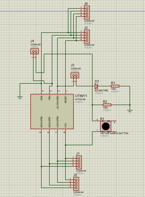
Image1 - Schematic
BOM (Bill of materials)
In the Protheus software is possible to see the BOM:
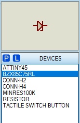
Image2 - BOM
- ATtiny85: micro processor;
- BZX85C75RL: Zenner diode ;
- CONN-H2 e H4: connector
- MINRES100K: resistor
- RESISTOR: Another resistor model also used on the board;
- TACTILE SWITCH BUTTON: button
Design
Subsequently, the board was designed, following the idea proposed in its planning and schematic to facilitate both its use and understanding, so each pair of digital connectors was placed next to the chip, with its pin positioned close at the door of ATtiny85.
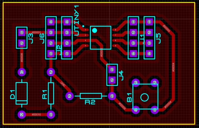
Image3 – Board design
Mod
After creating the SVG file of the board, the image was edited and separated into 3 new images to be uploaded to the mods, where the settings for the stages of tracks and holes were also made, with the difference that in the stage of holes the milling must be deeper than the trail.
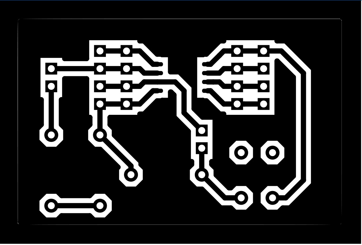
Image4 – Circuit trail mask
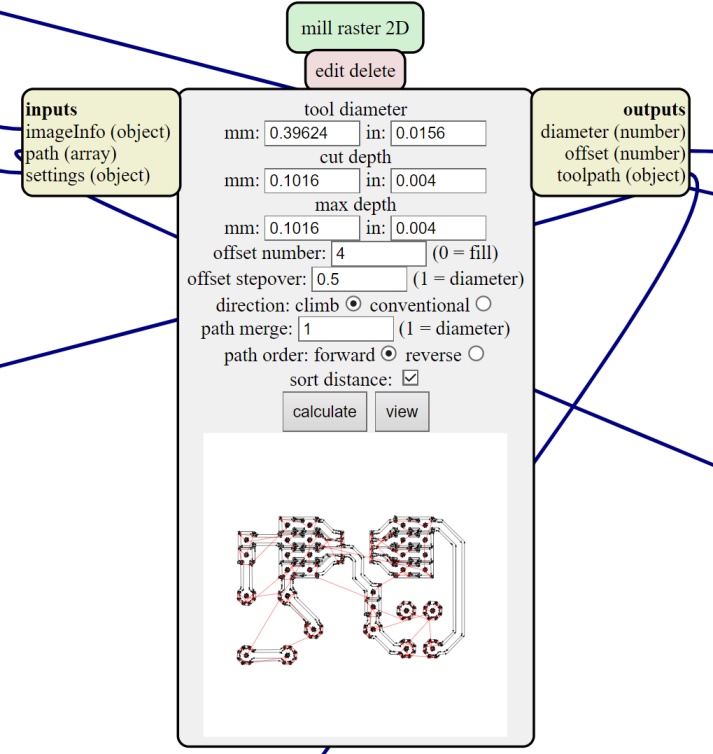
Image4.1 – Circuit trail Configuration
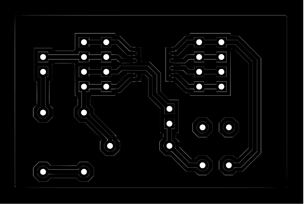
Image5 – Circuit Holes Mask
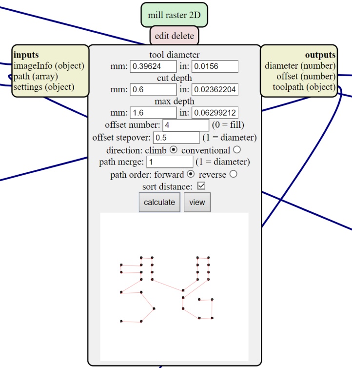
Image5.1 – Circuit Holes Configuration
The image below is possible to see the Circuit Edges mask used to cut the external part of the PCB.

Image6 – Circuit Edges Mask
Image6.1 – Circuit Edges Configuration
Milling
Using the parameters and the machine preset already shown in the Electronic Production week, the mill of the board be seen in the video below.
Video1 - Milling the board
Unfortunately, I did not take a picture of the welding process, but it is possible to show the result of the board.
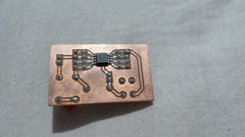
Image7 – Board ready Bottom
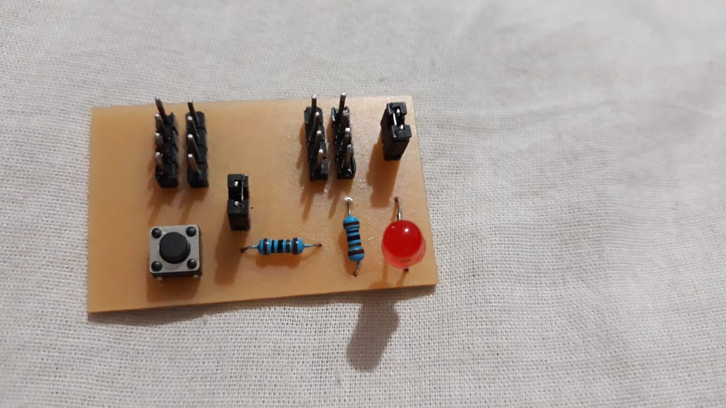
Image7.1 – Board ready Top
Obs: due to the humity of my city (in the in the middle of the amazon) the pcb rust a little, does not interfere with the operation of the PCB.
Tests
To perform this activity, the general use board with ATtiny85 (because of the pandemic I had supply problem to buy more ATTiny45, but the ATTiny85 is similar) made for the electronic design week assignment and an ultrasonic sensor HC-SR04. Before starting the activity, the sensor terminals were identified, being the supply, Vcc and GND, and the trigger and echo pins, so the next step is to determine which inputs will be used for each sensor terminal. For this purpose, a port on the ATtiny85 board was determined for each sensor pin. Finally, one tests was carried out, in the first test the board was powered with the Arduino + 5V and GND pins, in which the LED included in the board should light up when the distance identified on the sensor is less than 10 cm.
Video2 - Test- 10 cm test
Programming
The sensor used for the measurement test was the ultrasonic HC-SR04 for its use it was necessary to import the library to the Arduino IDE in the same way that other libraries were imported previously, the NewPing library was installed for this test.
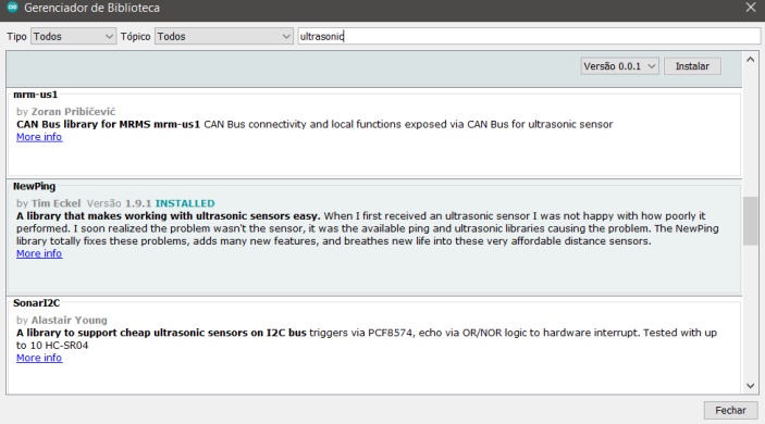
Image8- Import the Library
After installation, it was necessary to search for NewPing in examples and then select NewPingExample to use the ultrasonic sample code.
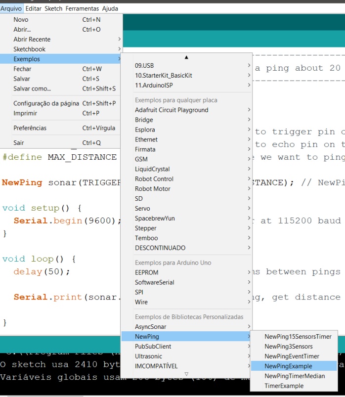
Image9- Search for NewPing
Attiny44 code
To use Attiny44 in the Arduino IDE, it was necessary to perform the steps that have been presented in previous weeks. In the code, the pins of the Trigger and Echo are defined, in addition to defining the maximum distance of the ultrasonic sensor. The creation of the sonar object has the Trigger, Echo and Max_Distance vestments. In the setup function the serial is started with a speed of 9600 and in the loop function the distance is read, and the value is printed in the serial, with that done the graphic part of this program was started.
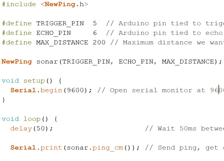
Image10- Code
I face some problems using python in the Neal code and because of that I prefer using the grafic as shows belows. Later using spiral managment I will try again.
Graphic part of the code
I used the “processing” for the graphic development of this activity, it basically allows sending and reading data from the serial, besides allowing the creation of layouts. A good youtube video about graphic can be found in Tech Explorations. First, processing.serial was imported to use the serial and then the myPort serial port was created. In the setup function, the 800x800-pixel window was started, and it started with a black background color, as the background is 0. PrintArray performed the listing of all available serial ports and in myPort the port we are using is opened. desired rate:
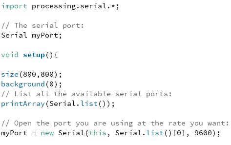
Image11 - Code graphic part
The draw function does the same thing as the loop function, and inside it there is a while that evaluates if there is any data in the serial, if this occurs, background (0) will be used to clear the screen and after that the value variable receives the data that is written in the serial. The variable “a” receives the distance from the ultrasonic converted to float and after that there is a mapping to relate the distance read by the ultrasonic in the serial with the dimension y of the window and the result is passed on to the variable y.
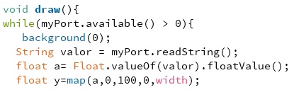
Image12 - plot grafic (Code draw function)
In this last part of the code, the size of the text, its color and location are defined, this occurs for the value read in the serial and for the text that is being presented on the layout screen. The loading bar was added with its position and size that varies depending on the value of variable y which depends on the distance read by the ultrasonic
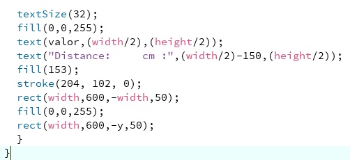
Image13 - Size, location and color
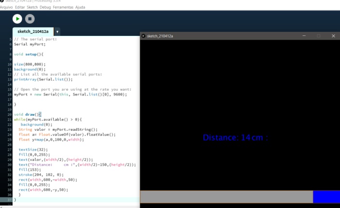
Image14 - Layout Screen
In the video below is possible to see the sensor measurement in real time.
Video 3 -Measurement Test
Group Assignment
To perform this task, the ultrasonic sensor was used, with the aid of the bench oscilloscope, its reference being connected to the sensor’s GND, and the probe to the terminals.
Connecting to echo
It was found that, as the distance identified by the sensor decreases, that is, the distance covered by the sensor’s audible signal decreases, the width of the high logic pulse also decreases, so it is understood that the width of this pulse is directly related to the identification of the distance read by the sensor. As can be seen in the video below.
Video 4 Group Test
I tried to change the material and the result was the same.
Video 5 Group Test new material
In the video 5 I stoped using arduino to supply power and use a power supply equipament that I had here in the lab.
The last test was using a spherical object and the result was not good. The echo signal was bad to analyse.
Connecting to the trigger
When connected, no pulses were identified on the oscilloscope, however, it is understood that it serves to start the reading process, perhaps the pulse.
Practical operation of the sensor
After the experiments, the practical functioning of the sensor was researched and it was identified that it works from a pulse sent by the trigger, then the sensor emits 8 pulses and waits for the return, at this moment the echo terminal sends a level pulse. high logic until receiving the return of the 8 pulses, the duration of the waiting for receipt of these 8 pulses is what determines the width of the echo pulse.
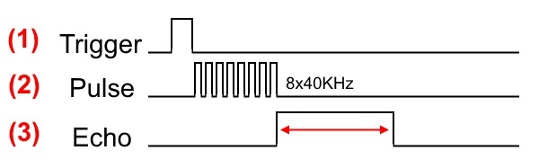
Image15 - Trigger, Pulse, Echo
Note: The breadboard was a sensor holder and didn’t effect the circuit. I still facing lockdown problems due to covid pandemic
Conclusion
This week was possible to learn how a sensor HC-SR04 works, and was a good opportunity to test a new PCB developed to be used in general applications.
- All the files done in this week assignment can be find in the repository