13. Output devices
Assignment
- Individual assignment:
- Add an output device to a microcontroller board you’ve designed, and program it to do something
- Group assignment:
- Measure the power consumption of an output device
For this week’s activity I decided to do two experiments, the first experiment was to connect a DC motor with a board that I developed, the second experiment was to control a servomotor with a graphical interface.
First experiment
To carry out this activity, it was proposed to use a digital output from ATTiny85 (because of the pandemic I had supply problem to buy more ATTiny45, but the ATTiny85 is similar) of the general purpose board to switch a BC548 transistor in order to drive a 5V relay, and consequently to drive a motor through the relay with 3V.
Relay Info:
| Reference | Value |
|---|---|
| Vcc power ON | 5 V DC |
| Maximum current | 10 A |
| Maximum Voltage | 127 V |
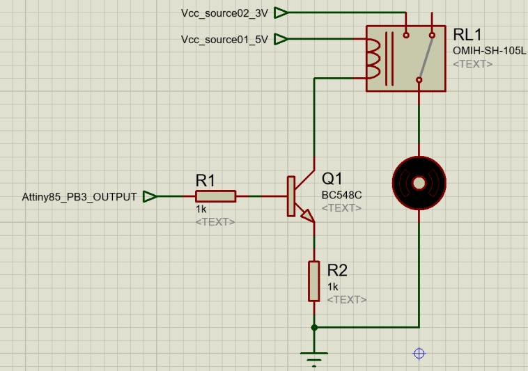
Image1 - Schematic
However, during the preliminary tests an error occurred, causing the ATtiny85 to overheat and burn.
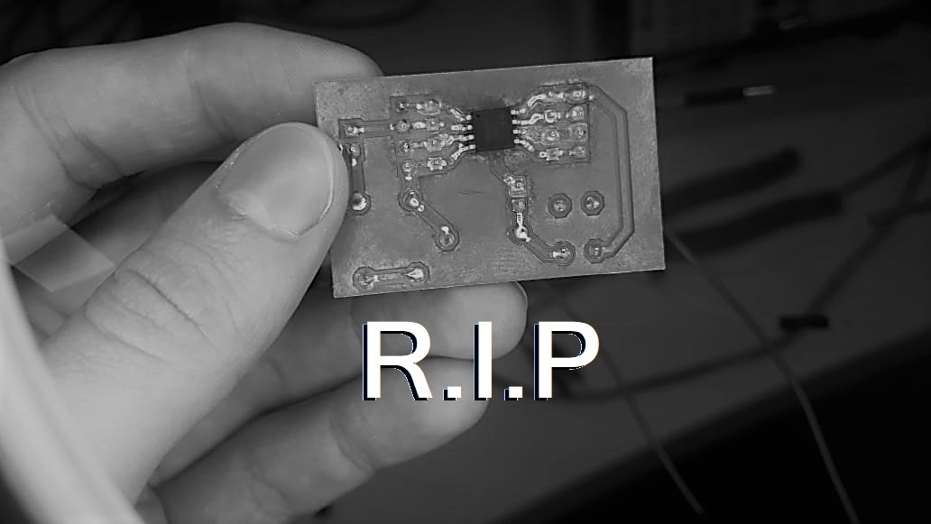
Image2 - Burnt board (R.I.P.)
In terms of appearance, the pcb does not look burnt, but it did not accept any more programs and it was not even possible to record the bootloader after this overheating, so it was concluded that the chip burned.
New board
With the first board lost, I started the production of a new one, even more simplified, which can be produced more quickly for the activity, because the focus of this activity is to perform the control of an actuator as well as measure the voltage and current values of the output of the component. For this board, I produced a design that allows 2 connections for each terminal of ATtiny85, reaching a simplified schematic, for that reason the chip was selected in the PTH packaging.
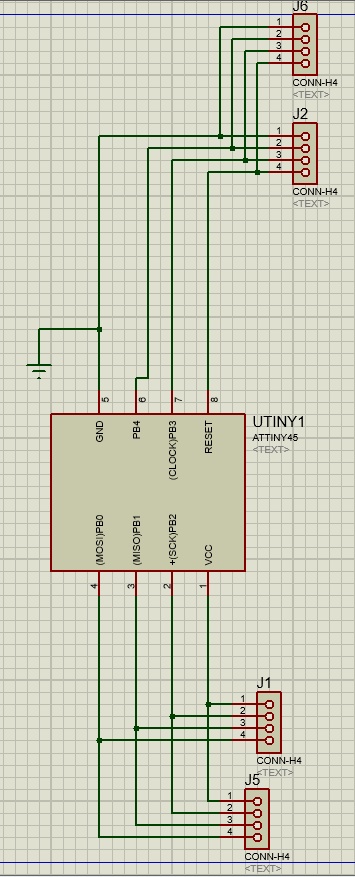
Image3 - New board schematic
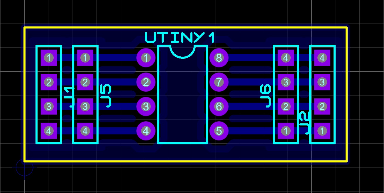
Image4 - New board design
After creating the design, the CAM RML files were created for each stage of the production of the board, being the tracks, holes and edges.
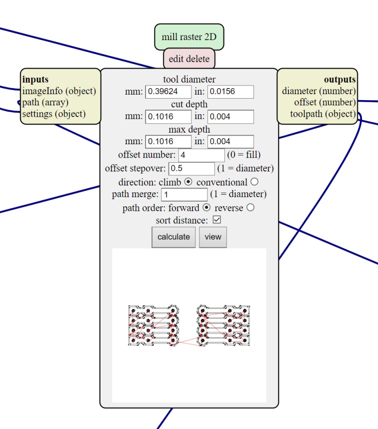
Image5 - tracks MODs
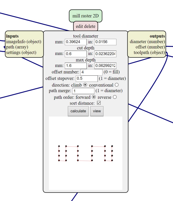
Image5.1 - holes MODs
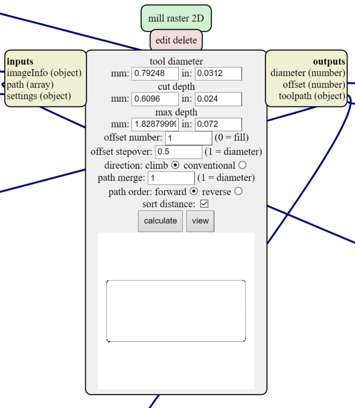
Image5.2 - edges MODs
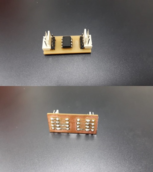
Image6 - Board ready
With the new PCB ready, I resumed the tests for carrying out the activity, this time with a different motor and with my finger pressed on the Attiny85 in order to always be monitoring the temperature of the chip. Even with a different motor, the chip got to heat up quickly, but it was possible to turn off the power quickly. Then, I tested a different way to start the motor, directly through the chip port. So the motor was turned on separately and isolated and with that I noticed that the motor, with the 3V previously used, needed 760-780 mA however, when consulting the datasheets of Attiny85, it is known that the maximum output current of the chip ports is only 50mA, so the motor in question was discarded.
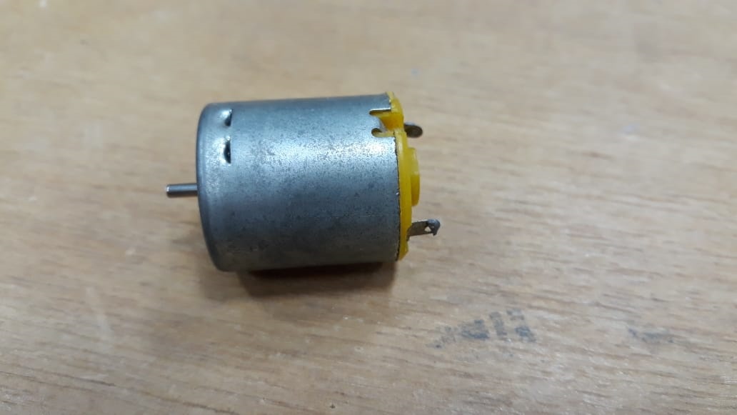
Image7 -
Then I selected a different motor. The label on this new motor indicated the need for 40mA but with 12V. When repeating the previous test, I noticed that it would need approximately 26mA with 3V, so the motor was used connecting directly to the PB3 terminal of Attiny85 where the motor would be on for 3 seconds and off for 3 seconds.
Video01 – Measuring the current
Then being able to control the motor, I measured the voltage and current values from the output of the PB3 port on the board, obtaining from the motor:
| Unit | Measure |
|---|---|
| Voltage | 4.45 V |
| Current | 19.8 mA |
| Power | 88.11 mW |
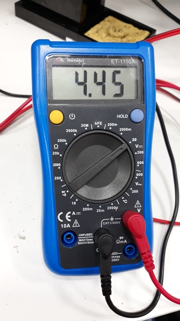
Image8 - Motor voltage
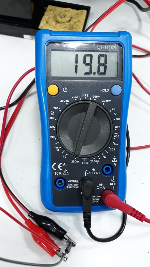
Image8.1 - Motor current
I also obtained the voltage and current values provided by the voltage source, by means of the bench in each of the motor states, obtaining the values:
| Unit | Measure (motor On) | Measure (motor Off) |
|---|---|---|
| Voltage | 5 V | 5 V |
| Current | 27 mA | 6 mA |
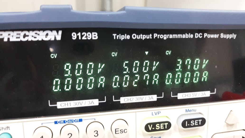
Image9 - Motor On
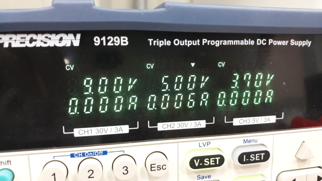
Image9.1 - Motor Off
Then, I tried a circuit similar to the test that resulted in the overheating of the previous board eliminating only the relay and the base resistor of the BC548 and the motor, just to see if it would be able to control, through the produced board, a 9V motor through the control of a transistor. It was possible to control it, but in this step, the voltage and current values of the port were not checked because I only tried to verify the functionality of this circuit. The complete circuit diagram can be see below.
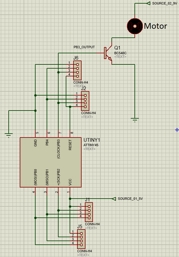
Image9.2 - Complete circuit diagram
Video02 – 9V DC Motor test
Below another video showing the circuit.
Video03 – 9V DC Motor test 2
Note: During the documentation I noticed that the protection diode in the relay coil was missing, I will do the test in the future by putting this diode in order to check if the lack of the component would actually prevent the Attiny85 from overheating.
Code of experiment 1
For this activity I used the program of the input device week with some changes. I added an if condition loop that when the distance from the ultrasonic sensor is less than or equal to 10, pin 3 of the board is in auto and activates the transistor which then will activate a relay that starts a motor, when the distance is greater than 10, the motor is off.
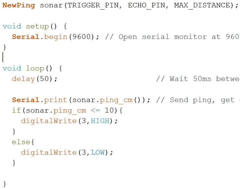
Image10 - Programming
Second experiment
To perform the control of the servomotor, Processing was used. I already used it previously together with the Arduino IDE in week11. In this activity, Processing was used to control the angulation of the servo.
Arduino programming
In the Arduino programming, the inclusion of the servo library and the creation of the Servo type object were carried out. In the setup function, the pin where the servo goes is connected and its position is declared and then the serial with 9600 speed is started. In the loop function, the verification is made if there is any value in the serial using serial.available and the value read is passed to variable a, with that the value of the variable is written in the servo that goes to the position read in the serial.
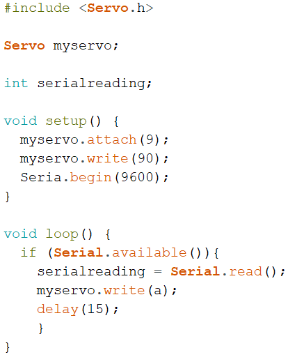
Image11 - Programming second experiment
Processing programming
For the development of this program, it was necessary to import ControlP5, which allows the use of a sliding bar. To import it is necessary to go on sketch then import and select add library.
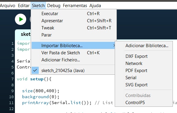
Image12 - Importing libraries
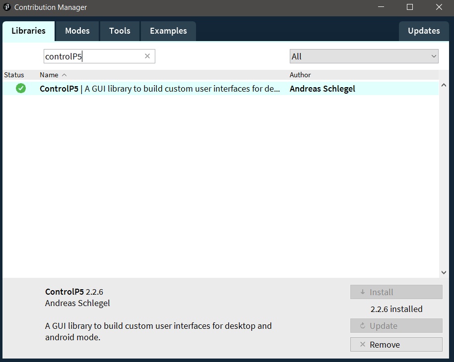
Image12.1 - Importing ControlP5
With the library added I started programming. As processing has been used previously, only new tools will be presented. Firstly, the controlP5 library was imported and the ControlP5 type cp5 object was created. In the setup function, the slider is created using the .addSlider, which will have its value passed to the angle variable. The other settings are position, dimensions, range, initial value and color of the bar.
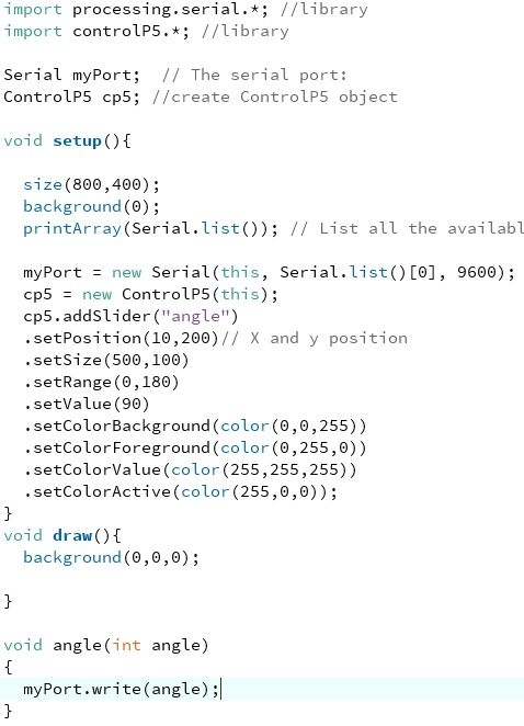
Image13 - Programming with Processing
The angle function receives the value of the angle variable and writes it to the serial that it sends to the Arduino that performs the servo movement.
The result can be seen in the video below
Video03 – Servo control
Conclusion
This week was possible to learn a lot aobut different kinds of output devices
- All the files done and datasheets in this week assignment can be find in the repository
Disclaimer When new Eletronic components (ESP microchips) arrives in the Lab. (problens because of the pandemic) I will develop a multi-pourpose pcb to improve this week assignment. Stoping using breadboard