Final project Development
As show in the Final Schedule I week20 divided the project in three main areas.
All the final project requirements was show in week 17
First I will show the Mechanical than the Electric and the programming
Mechanical Project
Robotic Hand
To understand how I should do my new final project, I did some research related to the cinematic study of a robotic hand, mainly for the movement of the fingers, this being the most complex mechanism of the project. I also used the Thingiverse platform to find models that came close to the idea I had in mind, and found this profile . I also found it on pakequis website website. My idea was to create a system that did not depends on nylon threads, but only on servo motors and links fixed to each other. Based on research and also on the project I developed in week 10 (Machine Design and Mechanical Design), my first step was to create a cinematic study based on the methods of Gruebler and Grashof, described in the books “Statics and Dynamics of Solid Bodies”, by the author Hibbeler. For this, I measured the distances between the joints of my index finger and created the following scheme below:
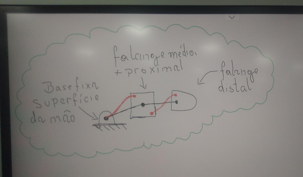
Image1 - Simplified Kinematic Study
After creating and studying the kinematic system described above, I started creating 2D sketches in SolidWorks using free shapes (resulting from the use of the “curve” tool), similar to human anatomy, for each of the components of the finger mechanism. For that, I searched on Google for an image that represented, in a simplified way, the bone structure of a human hand, and found the following representation:
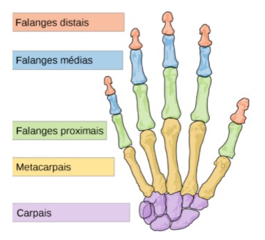
Image2 - Structures of the Human Hand.
Thus, the first structure sketched was the distal phalanx, as shown in the image below: To develop this CAD files I use the learning from week 3
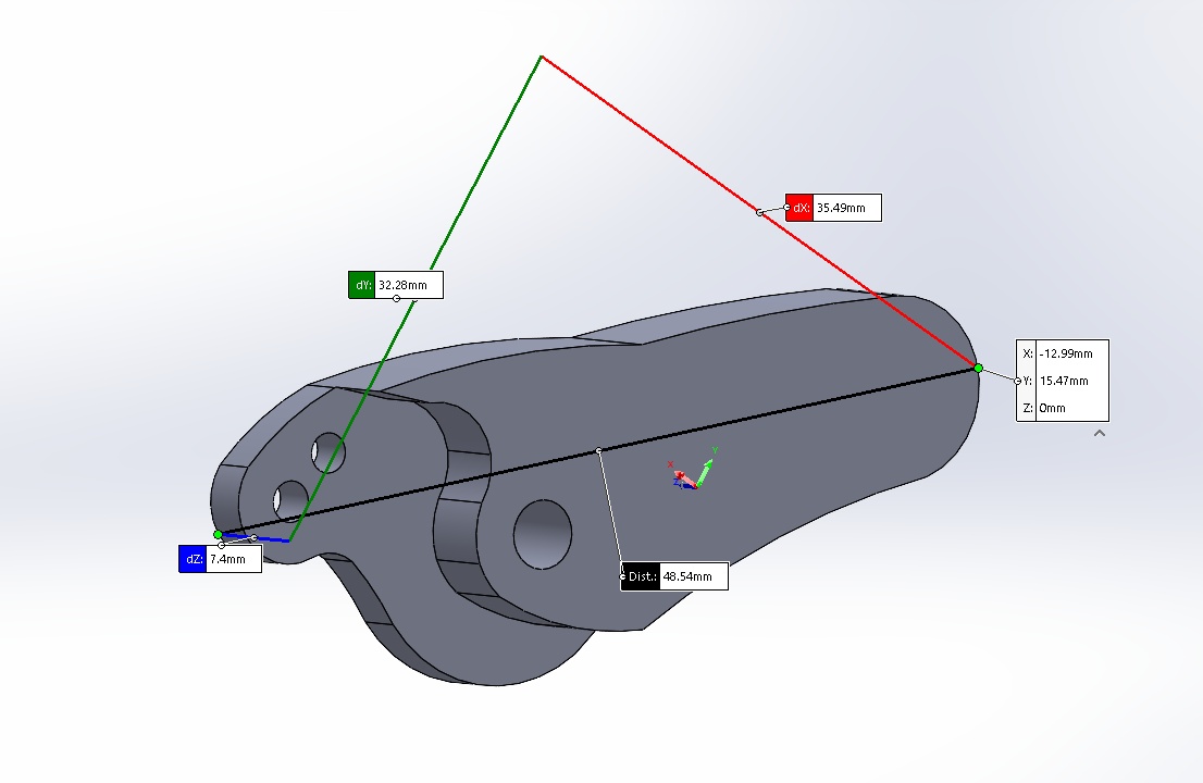
Image3 – Distal Phalanx
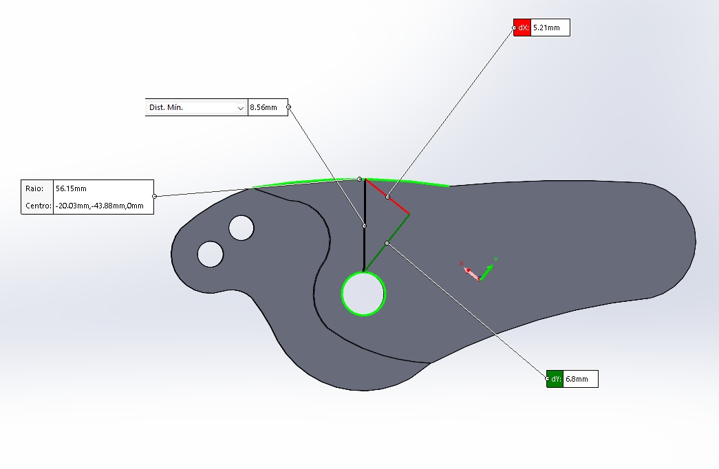
Image4 – Distal Phalanx
I used the same logic for the creation of the other structures, and obtained the following results for the middle phalanges:
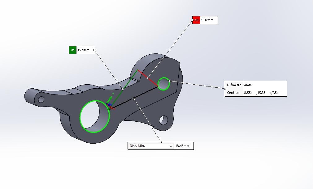
Image5 – Middle Phalanx
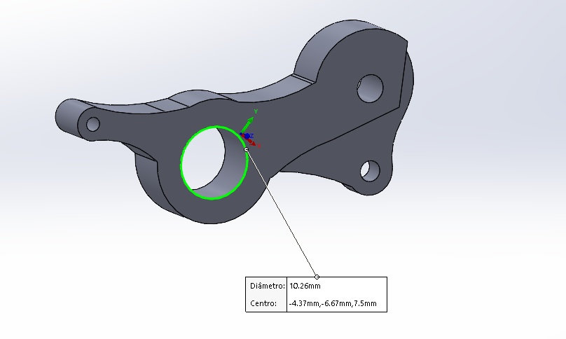
Image6 – Middle Phalanx
And also for proximal phalanges:
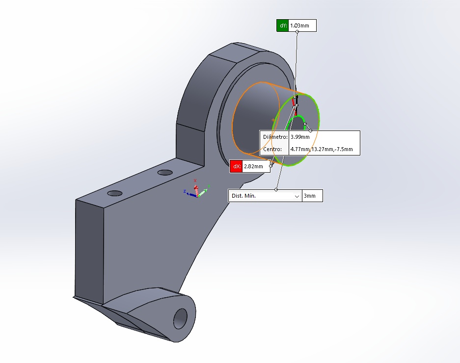
Image7 – Proximal Phalanx
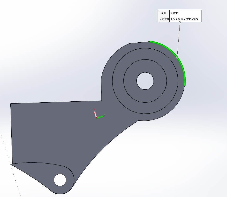
Image8 – Proximal Phalanx
It was also necessary to create structures that could support and limit the movement of each phalanx. Because of that, I created the following guide pieces, which connect the phalanxes of the fingers one by one.
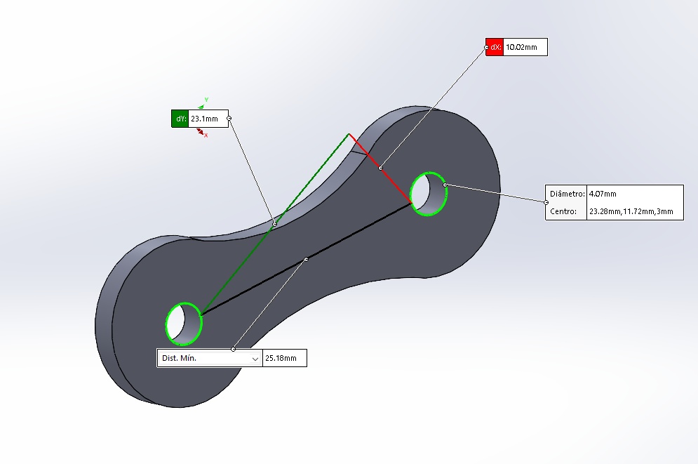
Image9 Distal Connection – Average 1
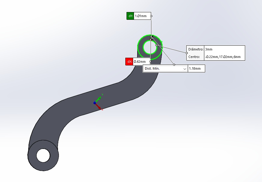
Image10 Distal Connection – Average 2
Based on previous research, I really liked the logic of using a board on which I could fix the servo motors, so that each of the servos would be connected to the structure of a finger, providing the movement. So, I made the following sign:
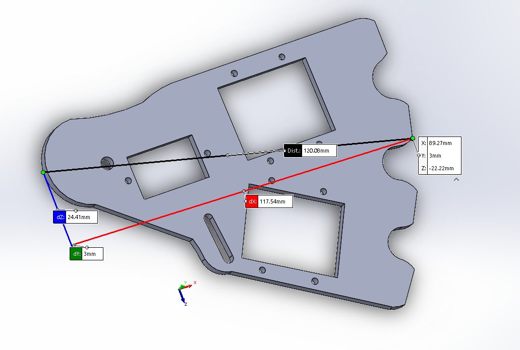
Image11 - board to fix the servo
Support Structure
In order to provide support and also to allow more movements to the robotic hand, it was necessary to create a structure composed of servo motors and a geometry favorable to balance during the application of the robotic hand movements. This structure was divided into 6 main parts listed below: Axis converter: This part makes it possible to change the axis for rotation of the “wrist” of the robotic hand.
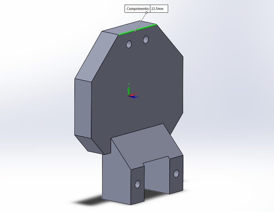
Image12 – Axis Converter: Side
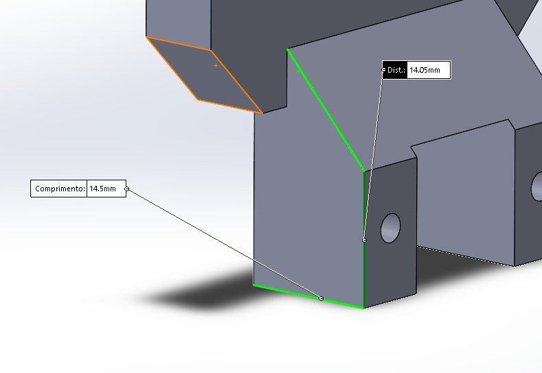
Image13 – Axis Converter: Basis
Rotation Base 1: Structure responsible for the rotation of the robotic hand around the Z axis, when connected to the axis conversion part.
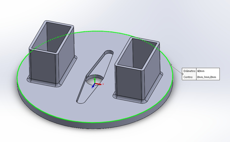
Image14 – Rotation Base 1: Outside Diameter
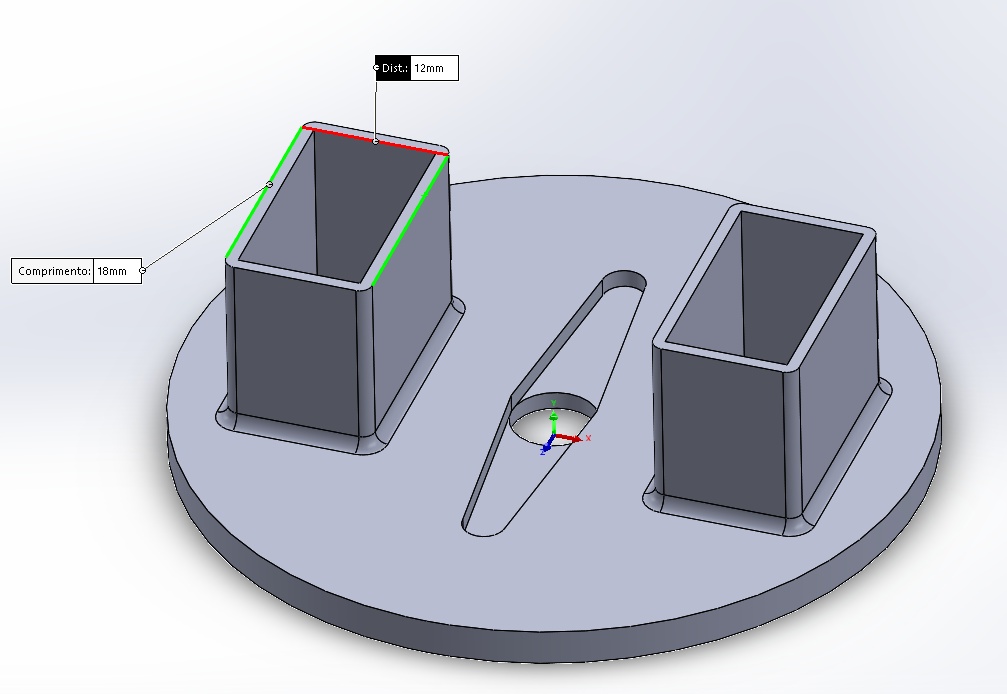
Image15 – Rotation Base 1: Supports
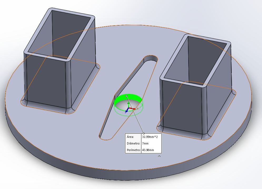
Image16 – Rotation Base 1: Internal Diameter
Threaded Articulation: Structure responsible for the rotation of the robotic hand around the X axis, when connected to the rotation gear. It has a servo motor compartment.
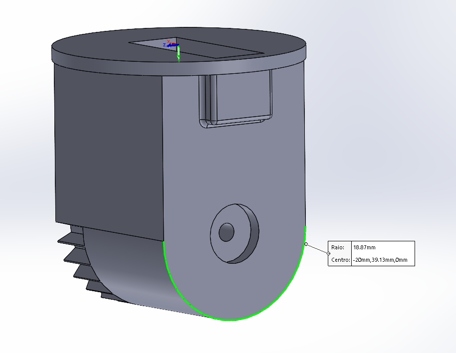
Image17 – Threaded: External Radius
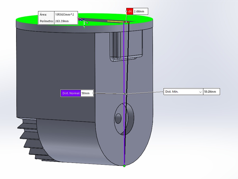
Image18 - Threaded: Maximun Height
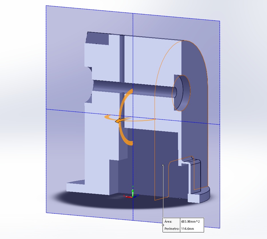
Image19 - Threaded: Section View
Rotation Base 2: Structure responsible for the rotation of the hand around the X axis, simulating the rotation action of the forearm, when connected with the fixed base.
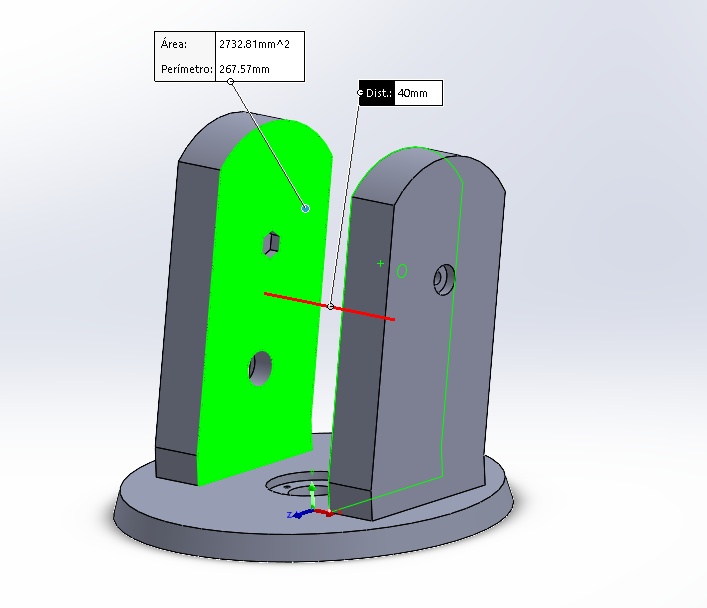
Image20 – Rotation Base 2
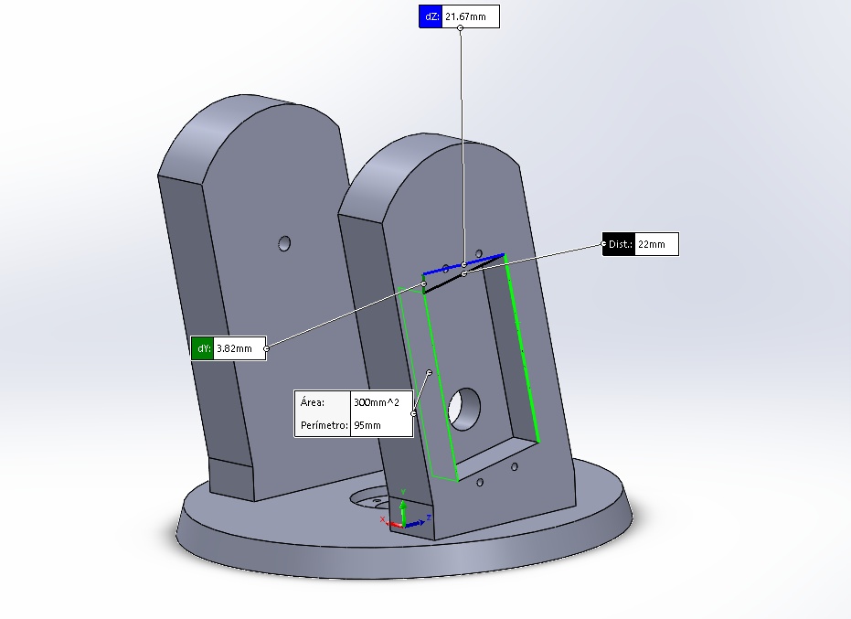
Image21 – Rotation Base 2
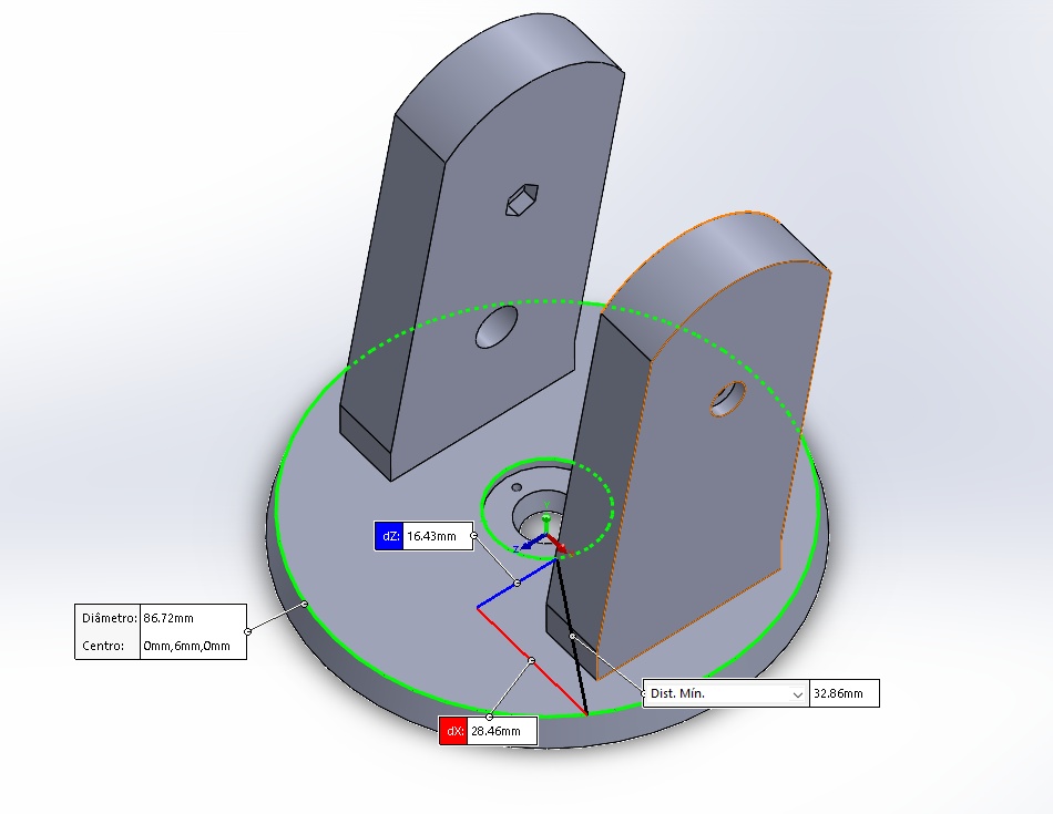
Image22 – Rotation Base 2
Fixed Base: Structure responsible for fixing the system on the control box. It has a servo motor compartment, which allows the rotation of the rotation base 2.
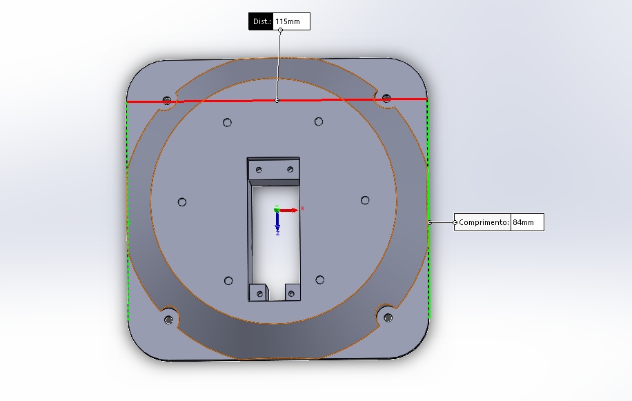
Image23 - Fixed Base
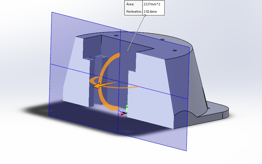
Image24 – Fixed Base
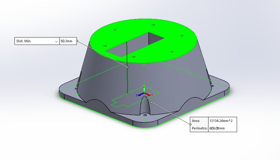
Image25 – Fixed Base
Servo-Finger Connection: Structure responsible for transmitting the movement of the servo motors to the finger mechanisms. Drive mechanism.
I did a Timelapse of the Rotation base in SolidWorks can be seen below
Video1- Timelapse Rotation Base SolidWorks
The final CAD with all the parts of the robotic Hand
Video2- Robotic Hand SolidWorks
3D Printing Results
The 3D printing parameters for all parts were: The knowledge gain in week 6 was very important to print well all the parts
-
Infill: 20
-
Layer: 0.3 mm
-
Material: PLA
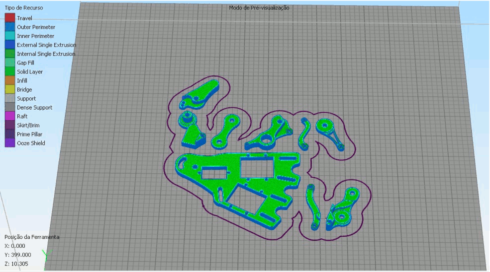
Image26 - Print parameters
The 3D printer used was the Sethi3D S2, which has a work area of 200x200x200mm, being able to operate in ABS, PLA, Flexible, PETG, among others.
After the 3D printing, I got the following results for the assembly.
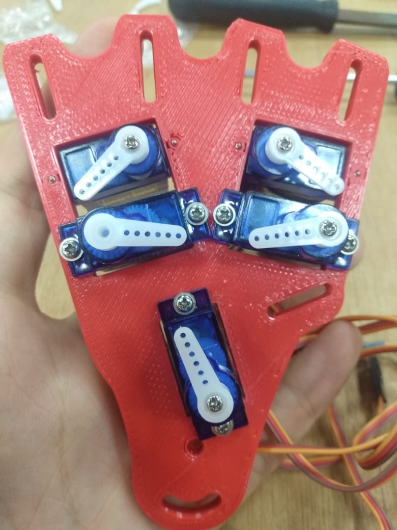
Image27 - Servo motor fixation
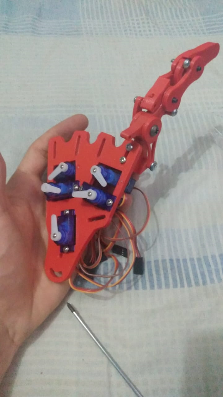
Image28 - Finger fixation
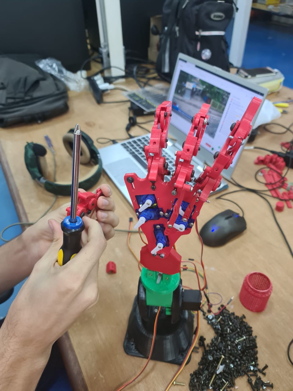
Image29 - Finger fixation 1
Component Box Manufacturing
To organize the electronic components and the printed circuit board of the robotic hand, I designed a box-shaped compartment in the VCarve software, as shown in the design diagram below. The knowledge gain in week 8 was very important to manufacture the Component Box.
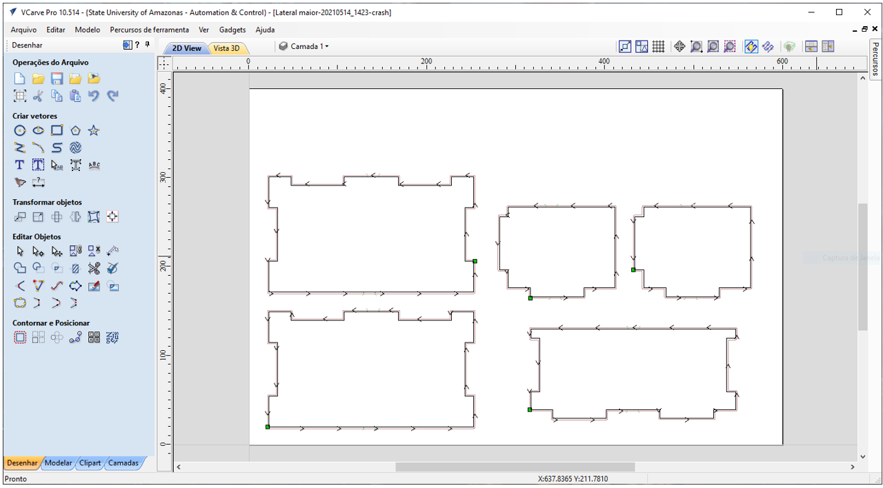
Image30 - Vcarve box project
The entire operation was performed on the ShopBot Desktop D2418 CNC machine, using cutting paths. The main parameters used were:
-
Cutting depth: 10.55 mm;
-
Initial dimension: 0.0 mm; (software parameter)
-
Tool: 3 mm flat top;
-
Number of passes: 9;
-
Vector machining: Off / Right;
-
Direction: Conventional;
-
TABs: 2 -> 12x3mm;
-
Route ramps: Smooth.
-
Material: 600x400mm polypropylene sheet
My first attempt at operation was on a 600x400x15mm MDF sheet.
Video3- Wood Box CNC Shopbot
Than I tried to pin the hand int he box.
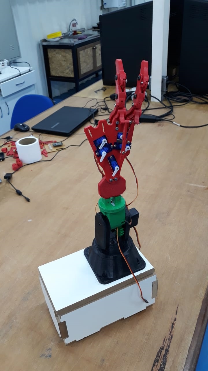
Image31 - Fixation of the Support Structure
But I drew the wrong connections, which made the box look very bad. The sides were not as thick as the fittings and, besides, the box was too big.
So, I thought about using the polypropylene sheets I had available in the laboratory, because besides being an easier material to work with because it does not produce many chips in machining, it also had the same thickness of 10.5mm as the fittings I have already had projected.
Video4- polypropylene material CNC ShopBot
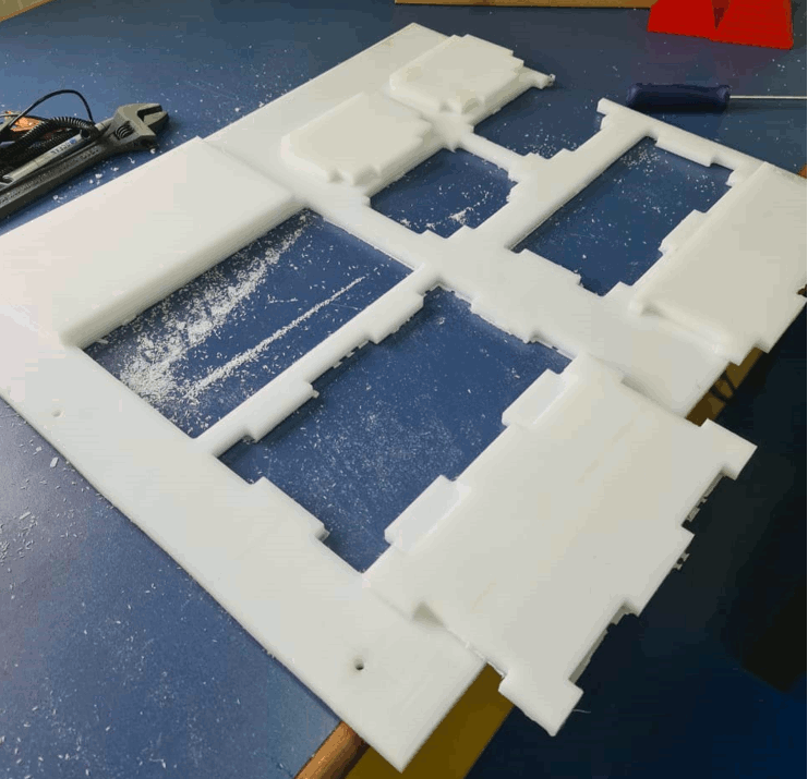
Image32 - polypropylene sheet
After machining, it was necessary to carry out a finishing operation by sanding the edges on which I applied TABs to fix the parts on the plate during machining.
After finishing I did the assembly and used threaded screws to fix the parts.
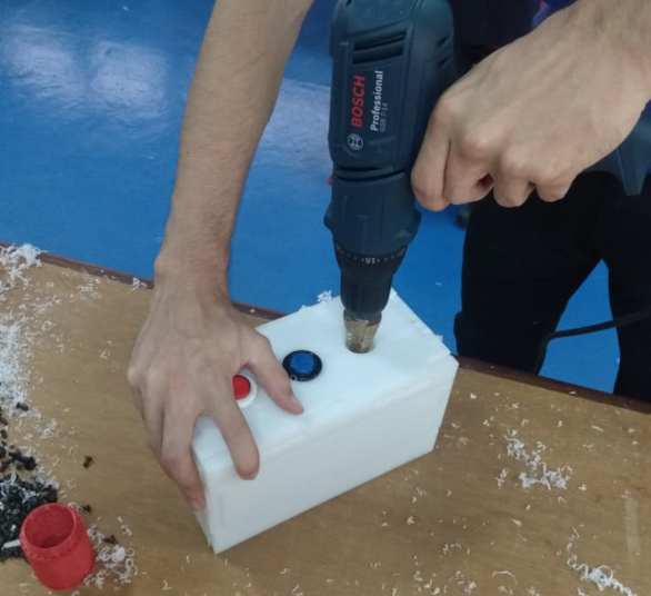
Image33 - Screws the parts
I also have a new idea to make one side of the box with acrylic to make it possible to see the circuit inside.
Video5- Acrylic side CNC ShopBot
So with the new Box I put some bottons and the Display. The Final hand with the box can be seen below.
Image34 - Mechanical Part Done!!
Extra in mechanical part:
I used the laser cut to engraving the Fab Academy Logo and year to the project.
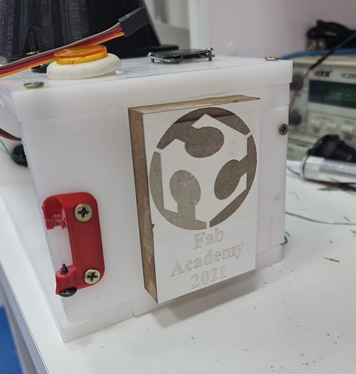
Image35 - Fab lab Logo and Year
Buttons explanations
Near to the Hand:
Green- Victory Buttom
Yellow- Random gesture
In the Side of the box
Red- Rock
Blue- Paper
Green- Scissors
Electric Project
The knowledge gain in week 5 and week 7 was very important to develop all the eletric part of the project.
Planning
For the creation of the circuit, the use of the ESP-WROOM-32 chip, also known as ESP32, was sought, as this chip allows wireless connection with other devices as well as support for servo motor control, which will be used in the project. For this, it was first planned how the circuit would be done providing its proper functioning, from its power supply to the functioning of its peripherals.
Project
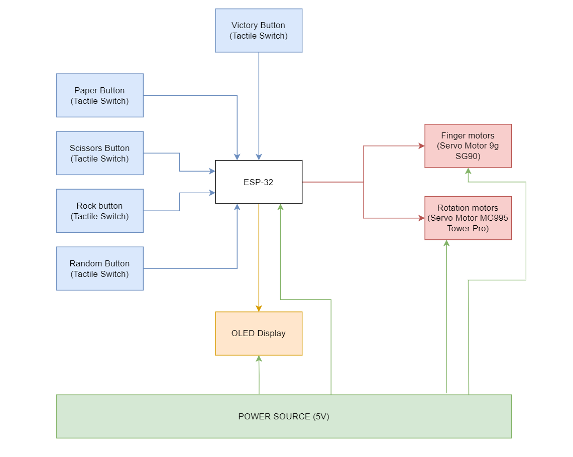
Image36 - circuit block diagram (missing)
BOM of the project
| components | Quantity |
|---|---|
| Contact button | 5x |
| Resistors 470 ohms | 5x |
| Servo motor 9g SG90 | 5x |
| Servo motor MG995 tower pro | 3x |
| ESP-32 DevKit 1 | 1x |
| 3-pin male connector bus | 8x |
| 15-pin male connector bus | 2x |
| 15-pin female connector bus | 2x |
| 5V power supply | 1x |
Then, the circuit was planned, in order to produce a dedicated board for the project, or even the set of boards, still allowing external connections for future unforeseen events.
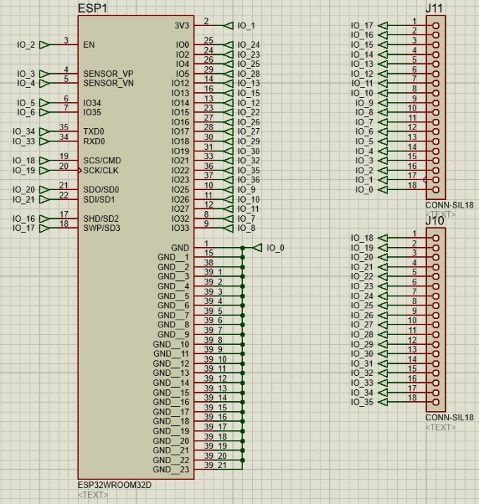
Image37 - Dedicated Board
Schematic circuit of the chip connections:
Video6- ESP Programming (Break-out boards)
Then, the next step would be the positioning of the servo motor connectors, connecting them to the outputs of the ESP-WROOM-32 chip.
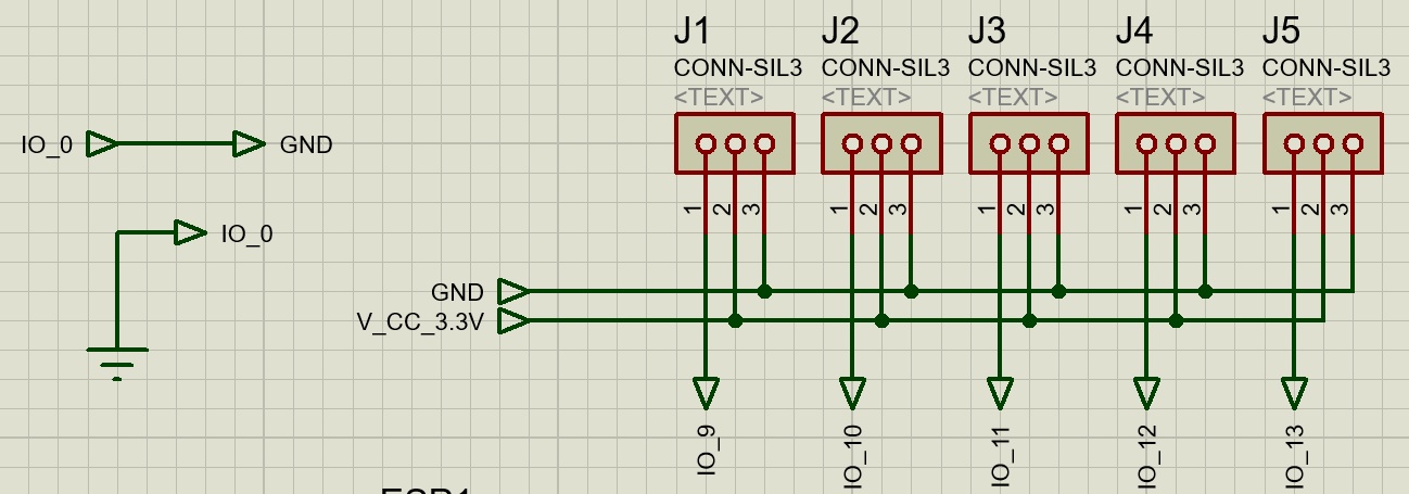
Image38 - Connections for servo motors
A connection was also made between pins 1 and 39 to the GND, as well as the voltage inputs for the proper supply of the servo motors. Then, the regulator circuit, as the expected voltage input would be 7.4V by means of two 18650 lithium batteries in series (3.7 V each). However, it is necessary to carry out the regulation of this voltage, therefore, 2 regulators were made on the circuit, one with 3.3V for the servos and for the ESP chip, and the other with 5V also for the ESP and the Display to be used.
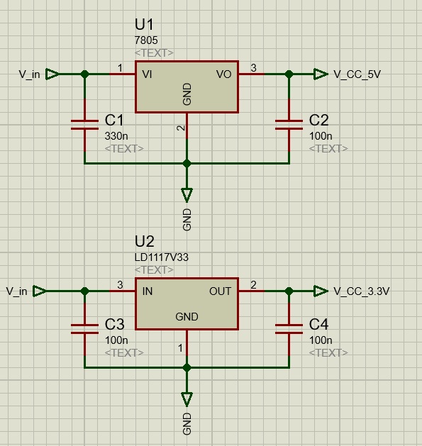
Image39 - Voltage Regulators
So far, having the schematic only missing the FTDI connections for its programming.
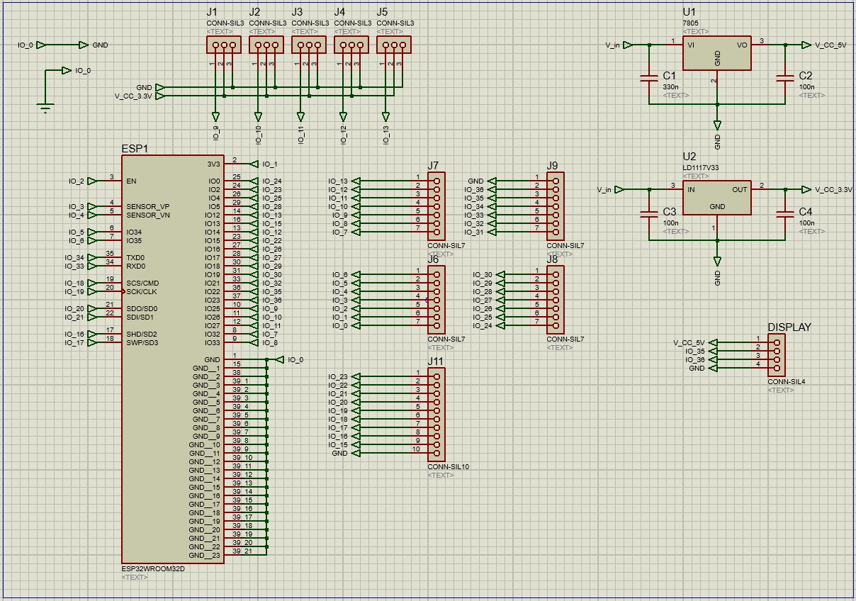
Image40 - Final Electric Project
Adjustment and news
Over time, there were 2 news: 1. A 5V source was obtained, allowing the supply of the circuit without the need for voltage regulation; 2. It was found that the servo motors work with the 5V supply while their PWM controls are powered with 3.3V, thus allowing the supply through this source to be obtained at the same time that they are controlled with the 3.3V output of the ESP chip WROOM-32.
Source test
Video 7- Circuit test
For the test, an Arduino UNO was used, in order to verify the information obtained as to the operation, and it was possible to observe that the engine functioned properly, without any type of heating of the components, or even of the engine, indicating that the information matches with the practice and can be applied to the final project.
New adjustment
The chip had not yet been delivered in time to complete the planned activities, so it was necessary to design another board, using the DevKit ESP32. For the model of the board containing the DevKit, the adjustment was made based on the new source, as well as the new connection to be used, obtaining a more simplified version, since it is assumed that the FTDI connectors to program the chip are already included in the DevKit board.
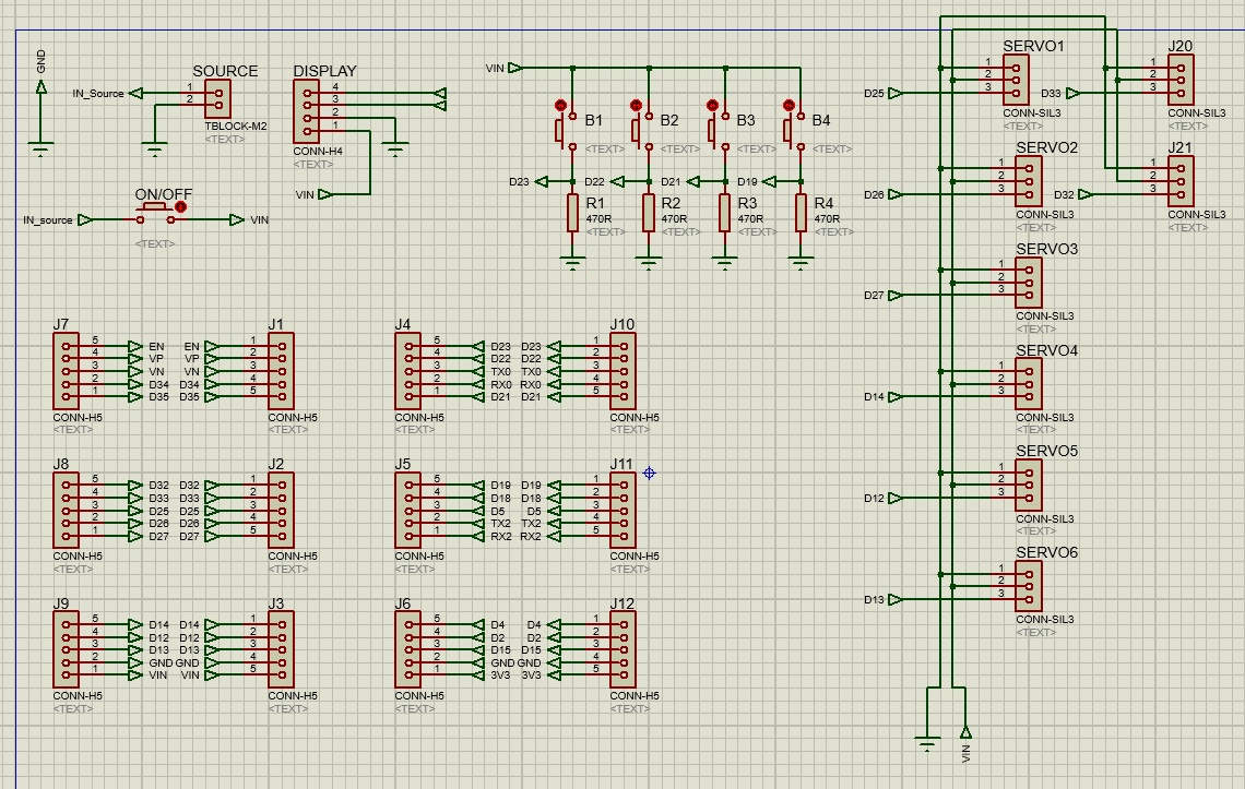
Image41 - Electrical schematic
Having made the schematic of the circuit, the board was designed. For the production of this design, the positioning of the connectors is planned in order to facilitate the connections of the peripheral components as provided in the design of the project chassis.
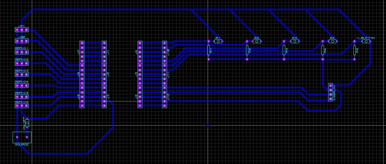
Image42 - Schematic of the circuit
The design made would still need to be inverted, to do this simply select the entire circuit and press the “Ctrl” + “M” keys for this, and then the external dimensions of the PCI.
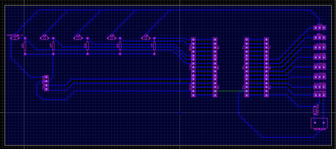
Image43 - Inverted Schematic
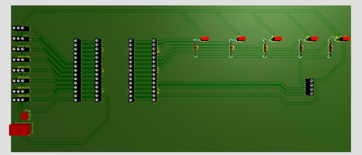
Image44 - Inverted board design + 3D visualization
Soldering the new PCB
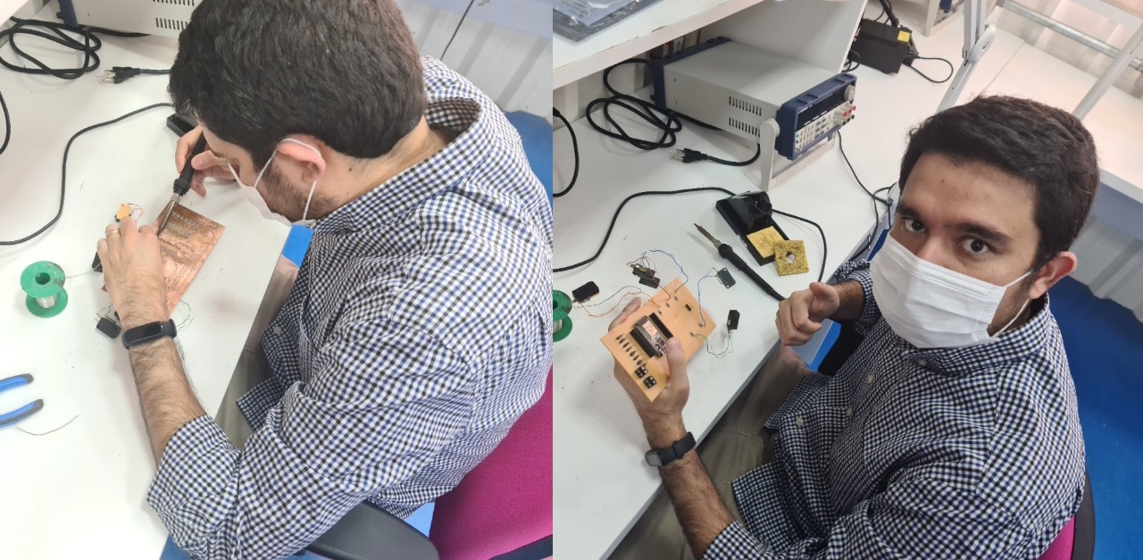
Image45 - Inverted board design + 3D visualization
connecting all the parts on the board
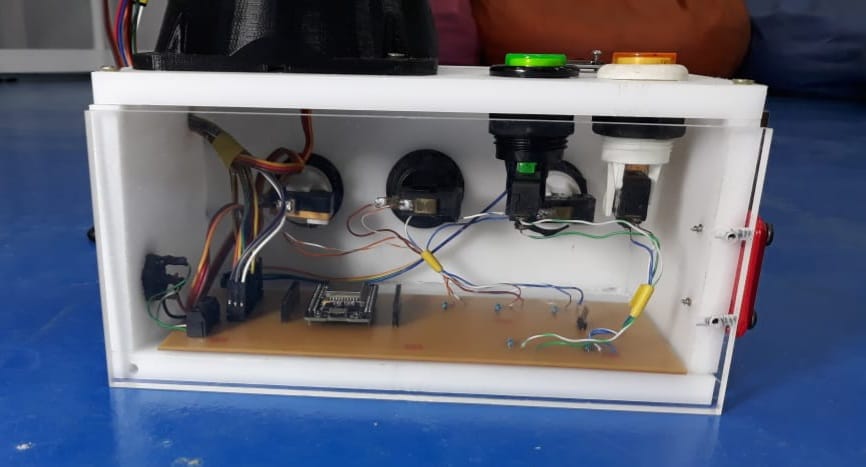
Image46 - Inverted board design + 3D visualization
Conectting
Programming
The final programming of this project used much of the code that was developed in week 15 (Interface and application programming). The goal was to improve the Jokenpo game that was developed and for this, a new robotic hand was included that would be used as the player’s opponent, in addition to adding a score counter to know who won. The player can select the hand positions between rock, paper, scissors or random.
The project development can be represented by the block diagram below, which is divided into three main cores: software, hardware and screen.
The hardware is the physical part of the project that has the inputs that are the buttons and the outputs that are the servos.
The software is responsible for analyzing the input data and configuring the output data, in addition to sending the data to the screen or being controlled by it as well.
The screen is responsible for presenting the winner or controlling hand positions in a similar way to the input buttons.
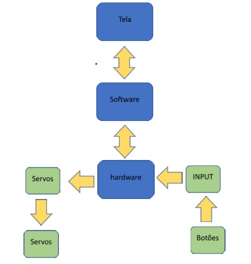
Image47 - Block diagram
Arduino Code
I added some commentaries to the code to make it easy to understand. As previously presented, this code is an improvement of the one developed in week 15 so only the changes that were made will be presented and any other questions about the code can be resolved by reading the documentation for the week 15.
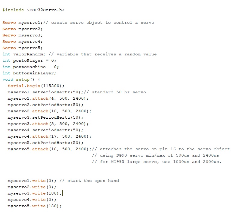
Image48 - Setup
Variables for the player score, the machine score and the player’s win button have been added. When the player wins a round, he will press the player’s win button which will add a point for him, but if this button is not clicked, then the machine will gain a point. During the setup, the initialization of the hand occurs in the open position. The angles of the servos for this are the ones that are being presented above.
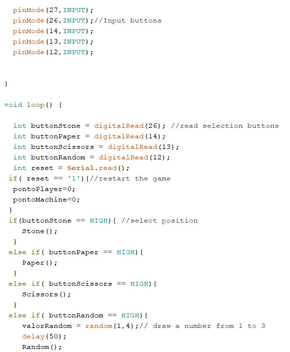
Image49 - Buttons Code
Inputs of the robotic hand positions are declared and depending on which one is pressed, the hand will make the related movement. The system also has a reset variable that if receives the value 1 in the serial, it will reset the machines and the player scores to restart the game.
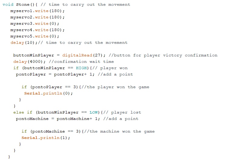
Image50 - Score Code
The logic responsible for checking if the player wins the round was included in the hand’s position functions. For this reason there is a 4 second delay to press the win button, if this does not occur the system understands that the machine wins the round. Inside the two IF that register the score for the player or the machine, there is another conditional loop that checks if any of the players scored 3 points. If this occurs a variable is sent to the Processing to identify the winner.
Processing
In Processing, which is the project screen, the code from week 15 was used, but a verification of the winner was added.
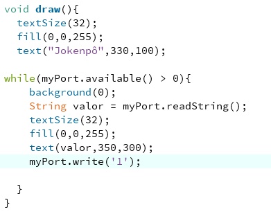
Image51 - Processing Code
A While loop was added to be active when some data from the serial is received. In this project would be 0 for the player’s victory and 1 for the machine’s victory. Depending on the result, a victory message will be displayed. To restart the system, the Processing is responsible for sending 1 to the software that will receive it in the reset variable and restart the game.

Image52 - Victory message
Update In the week 14 I developed a new ESP PCB board that I also used in the final project. Picture Below.
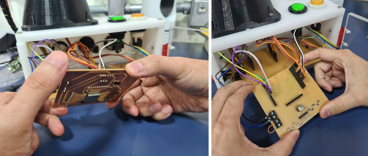
Image53 - New PCB in the Final Project
Below the hero shot of the Project
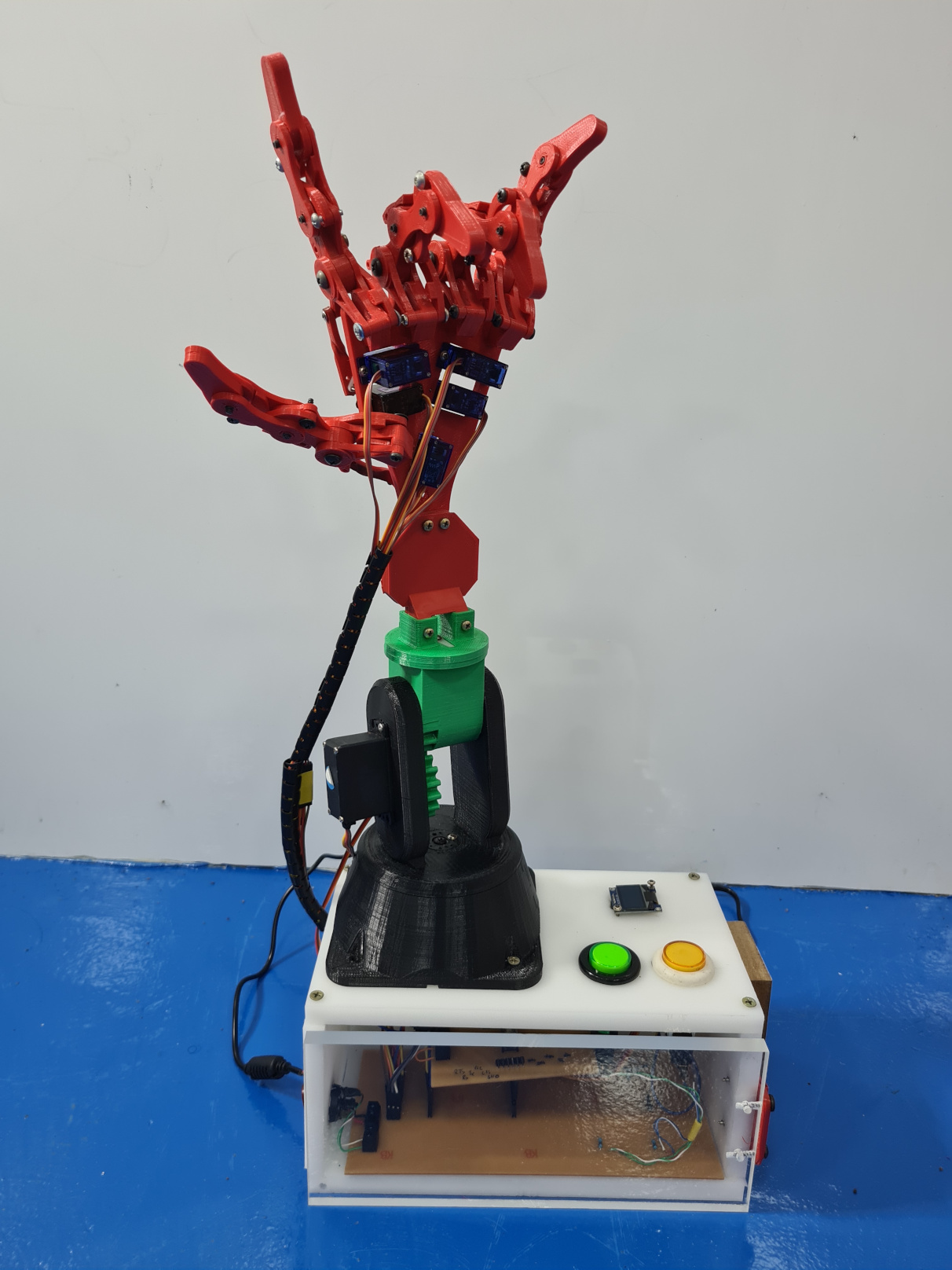
Image54 - Hero Shot of the Final Project with new ESP PCB
Below video of the hand working with the new pcb
Video 8 -Test with new PCB
Files of the Final Project
- All the programming files of the final project can be find in the repository