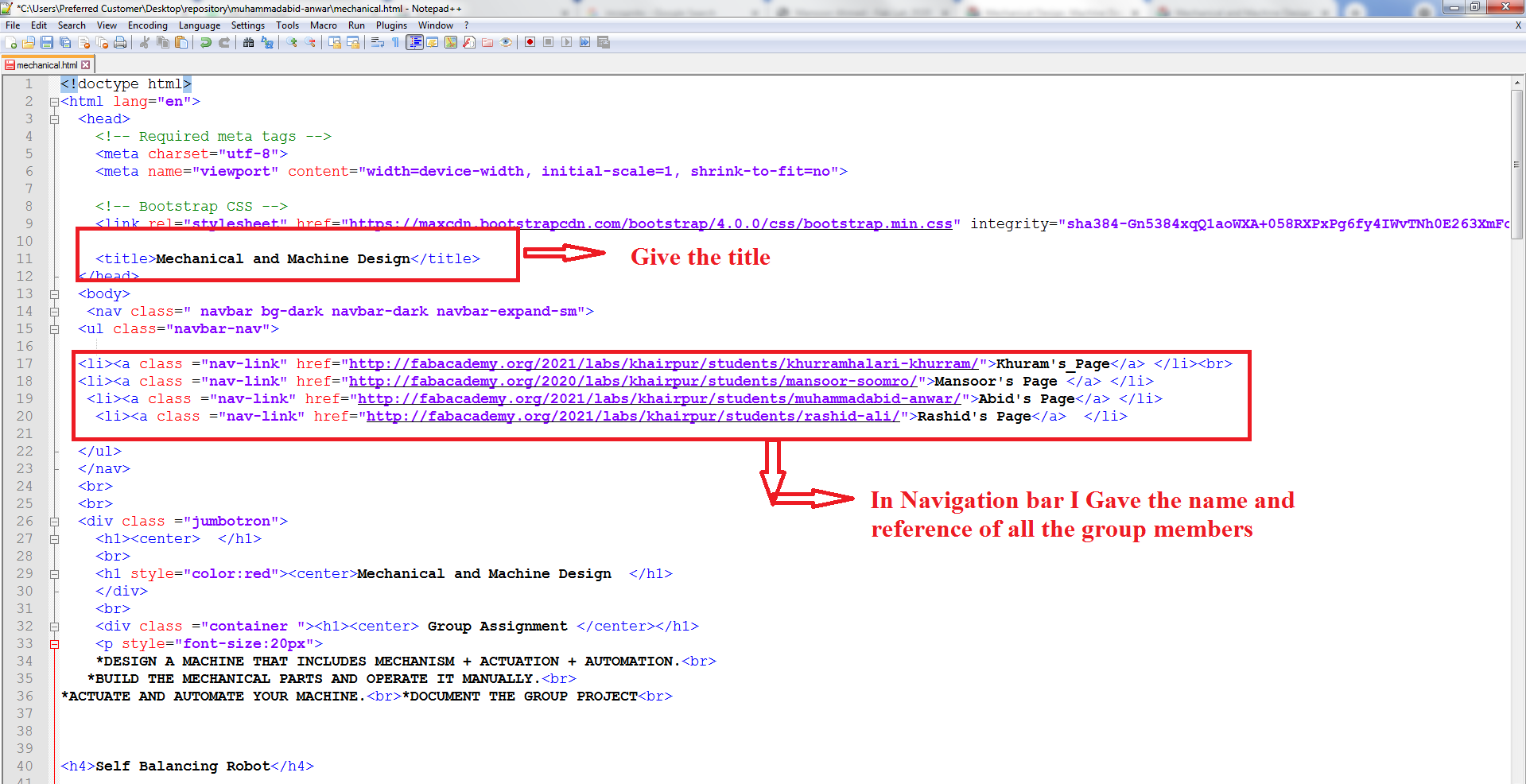
Group Assignment
*DESIGN A MACHINE THAT INCLUDES MECHANISM + ACTUATION + AUTOMATION.
*BUILD THE week10 PARTS AND OPERATE IT MANUALLY.
*ACTUATE AND AUTOMATE YOUR MACHINE.
*DOCUMENT THE GROUP PROJECT
Self Balancing Robot
The task for this week is to create a machine that includes mechanisms, actuation, and automation. We considered a variety of options in light of the above requirements, with the self-balancing robot coming out on top due to its importance and benefits.
Theory of Self balancing Vehicles
A pendulum that is inverted will not be able to balance on its own. Try balancing a broom stick on your fingers as an example of this You can't stay in one place, you have to move your finger back and forth. This is exactly what the vehicle is doing, its moving back and forth so that the center of gravity will always remain under the wheels.. To drive the motors we need some information on the state of the robot. We need to know the direction the robot is falling, how much the robot has tilted and the speed with which it is falling. We'll use a combination of a gyroscopic sensor and an accelerometer to acquire this data. MPU6050 is the sensor we'll be using. We integrate all of these inputs to create a signal that controls the robot's motors and maintains it balanced.
My Role
In this week, my task was to 3d print and Laser cut the parts designed by mansoor . Secondly I have to document this week task and present in the review.
Laser Cutting and 3D Printing
As when the design was ready I go through the Laser cuter machine to cut the components as :
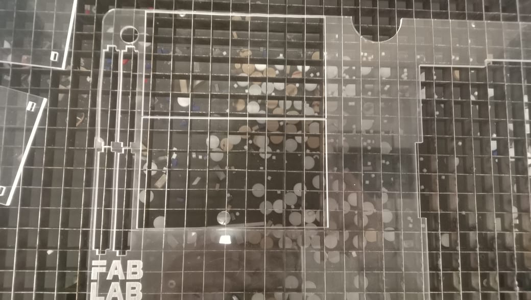
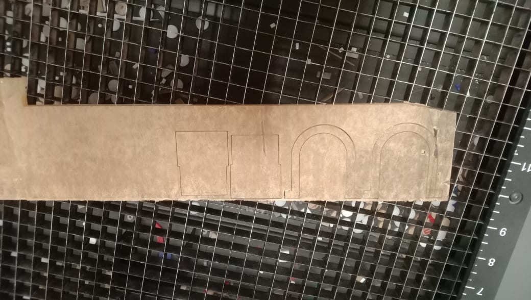

3D printing and Laser cutter PARTS
Documentation and Presenting
The second task of mine was to document all the task done in group assignment and present the group assignment to neil in review
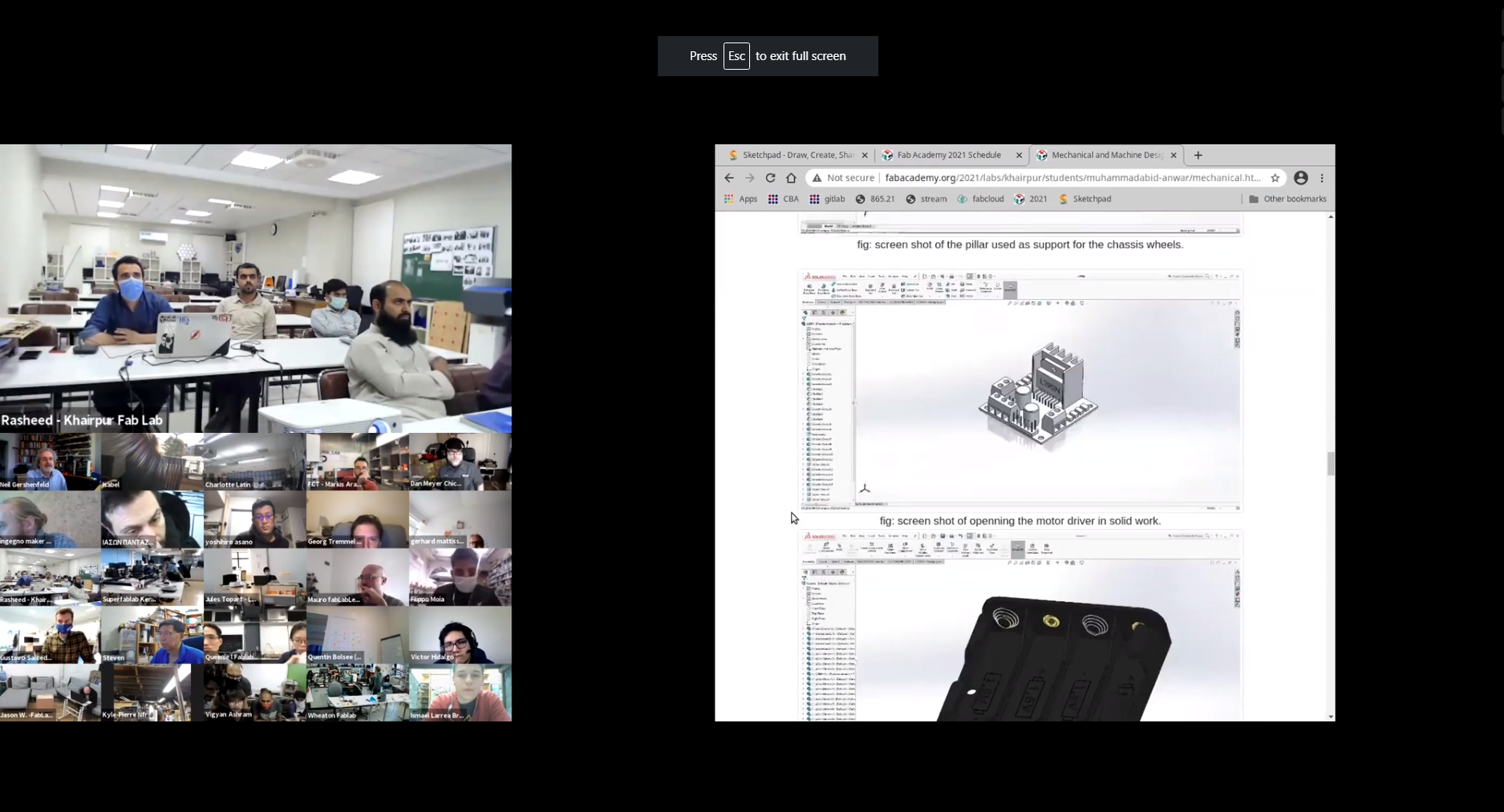
Documentation and Presentation on review
Conclusion
The field of robotics has dominated the minds of people around the world. It was the dream of humans to create such a machine that replicates
them in every aspect of daily life. Two-wheel self-balancing robot is also a development in the field of robotics. This two-wheel self-balancing robot is
based on the concept of Inverted pendulum theory. This type of robot has gained fame and interest among researchers and engineers because it utilizes such a
control system that is used to stabilize an unstable system using efficient microcontrollers and sensors. Two-wheeled balancing robots can be used in several
applications with different perspectives such as an intelligent gardener in agricultural fields, an autonomous trolley in hospitals, shopping malls, offices,
airports, healthcare applications or an intelligent robot to guide blind or disable.
Individual Assignment Part 2
During our Global evaluation our evaluator told that the above individual assignment is not enough to be helpful in group. As we use the builden aurdino in the group assignment so our global evalutor suggest me and my friend
Rashid to design and made custom Pcb Controller For the Project. So I and my friend after consulting with our Instructor Divide the work in two Task as :
The designing , rml generating and the Milling will be done by me and the remaining task as the soldering , testing , bootloading , program uploading and replacing the costum Pcb with builden Arduino will be done by Rashid.
Designing The Controller
After calculation the number of pins required for input and output of my project I decide to sketch the satsha kit.
A Satsha kit uses mostly the same components as we use in arduino microcontroller , the ATmega 328p. From this data sheet, I realize that what possible inputs and outputs I can get from this.
As mentioned in the Satsha Kit web page it uses 16Mhz instead of 8Mhz, also a crystal instead of resonator,So by Geeting help from this I start to design the satsha kit
and and try to modify the pins.
As according to my requirment.
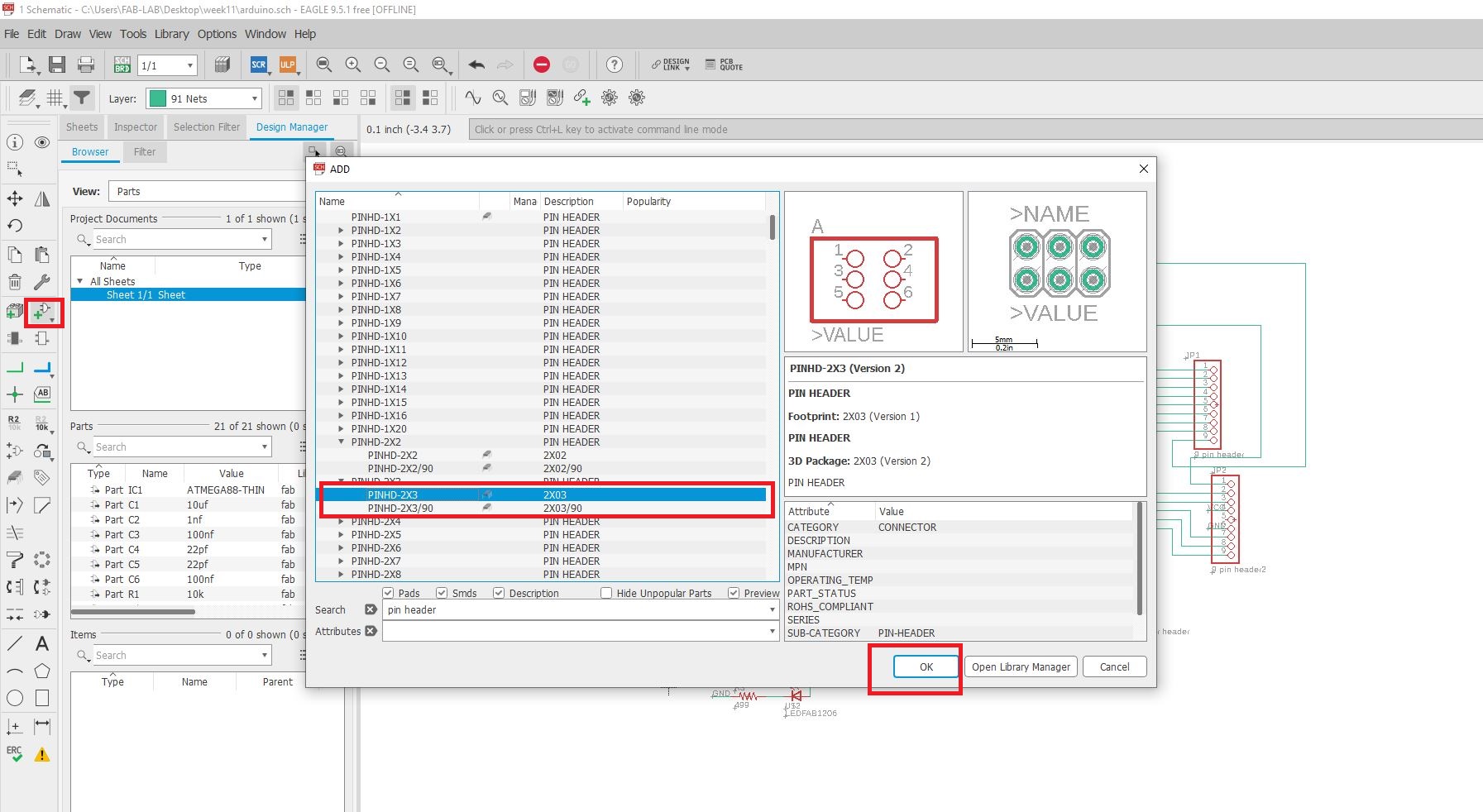
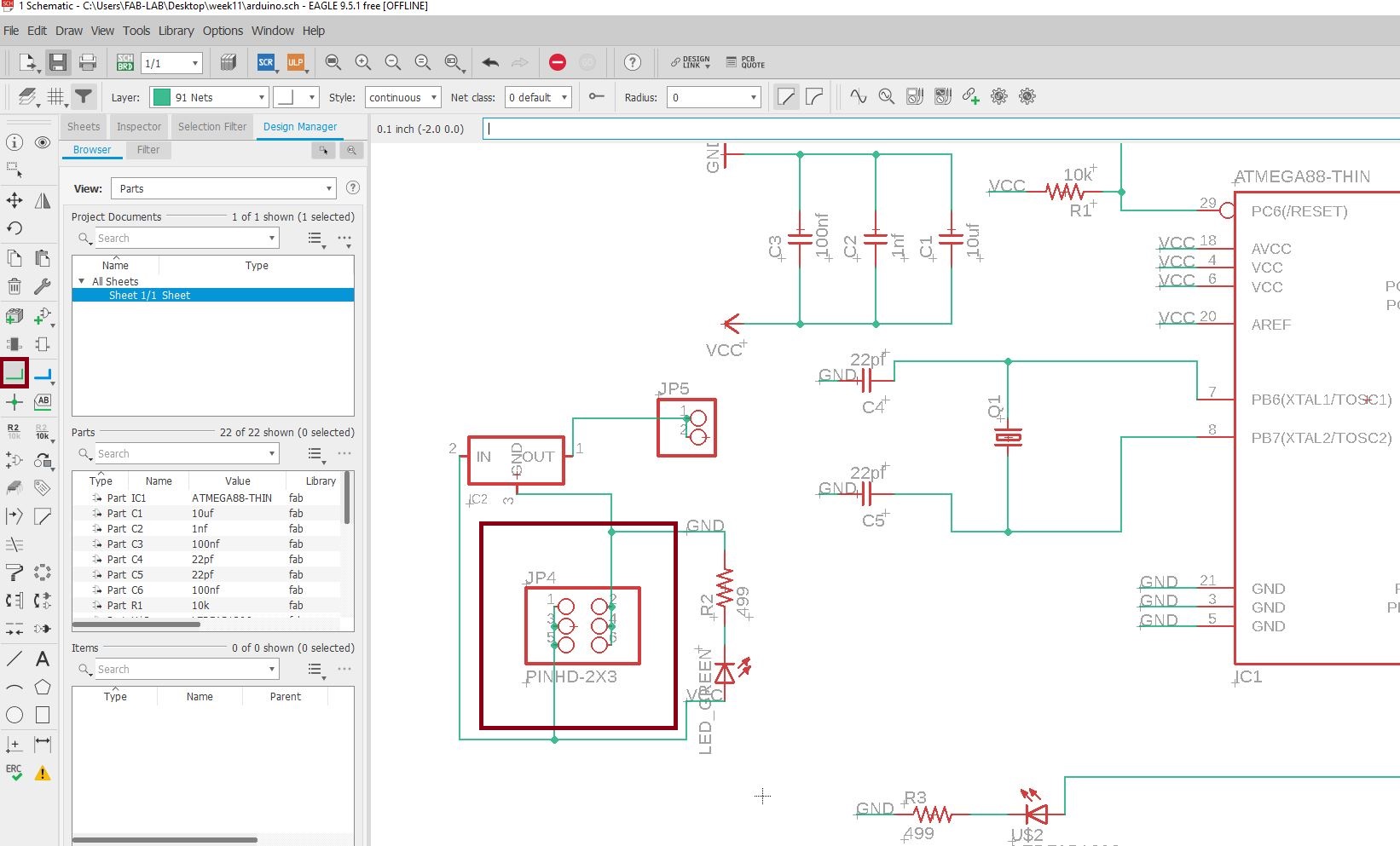
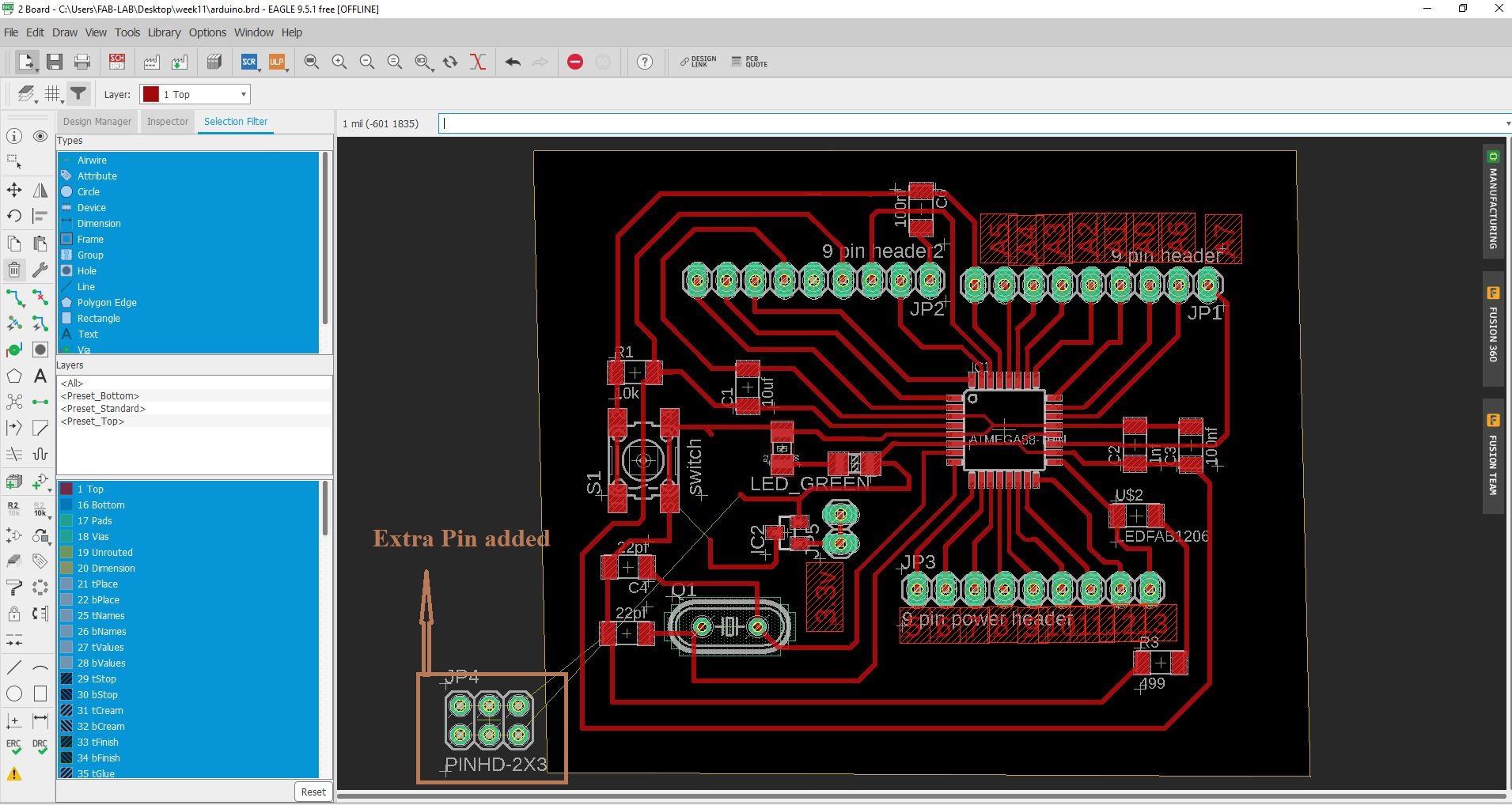
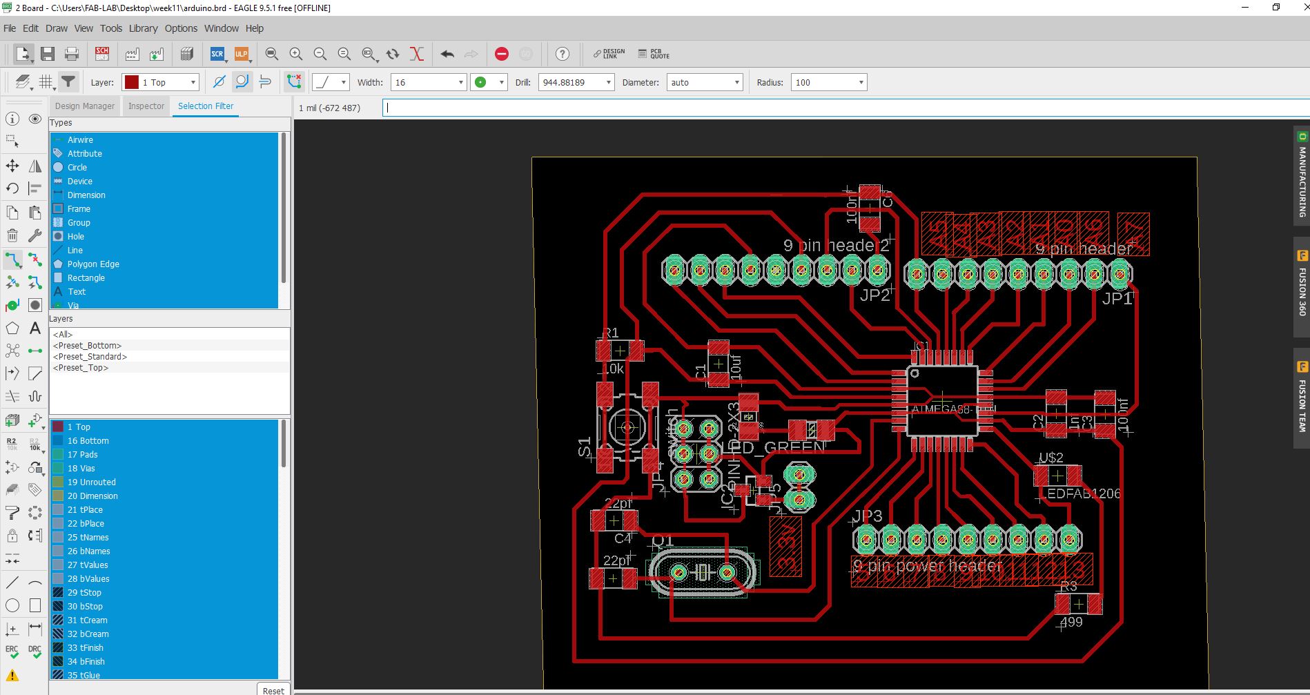
I Start by opening the satsha kit in Eagle software and add HEader from adding component that i can use different input for the Motor drive and Controller
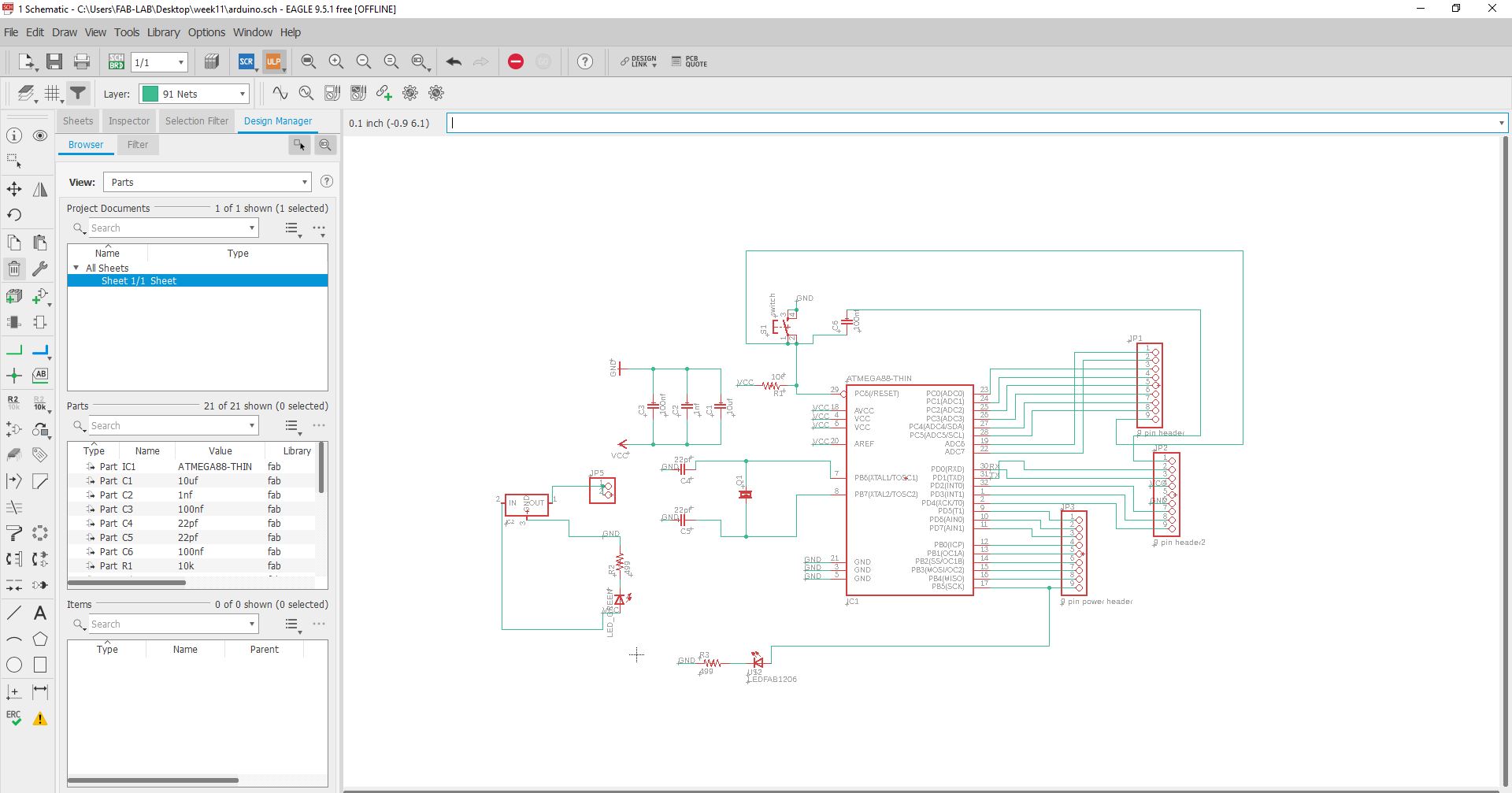
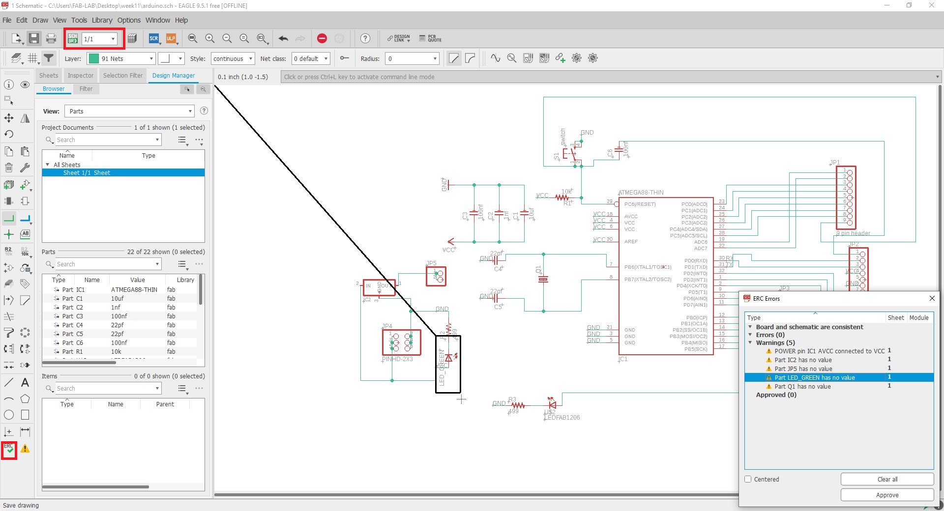
After that I check ERC and move toward SRH circuit.
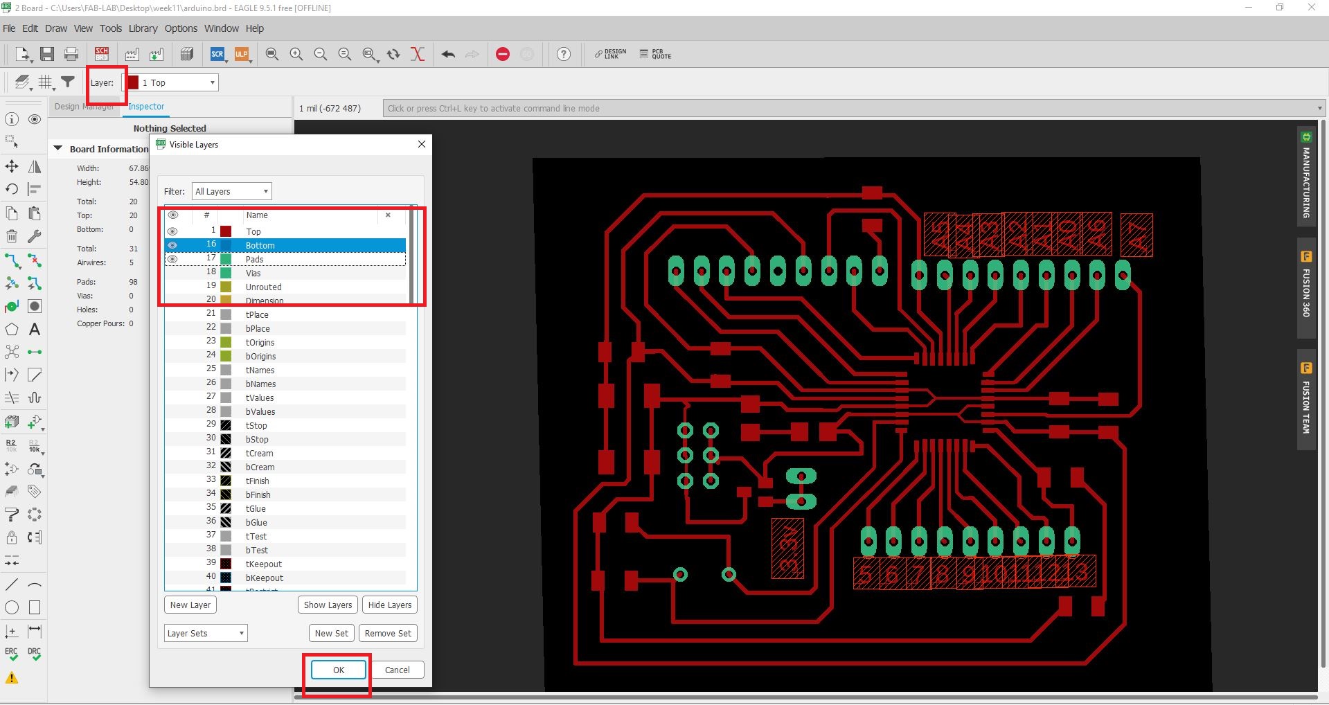
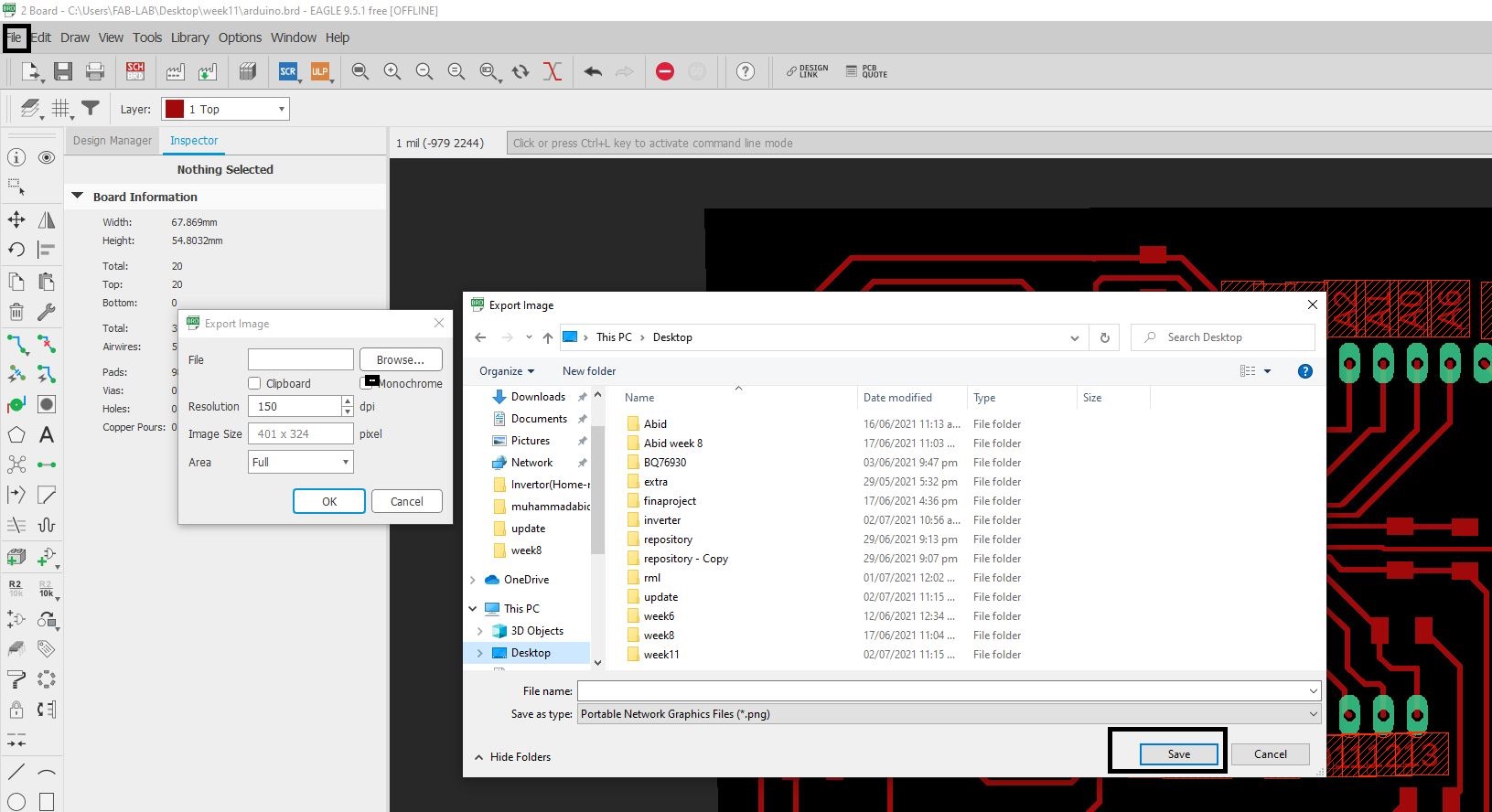
Before saving the file I hide all the layer except the first three and after hat i click on file then export and Png:
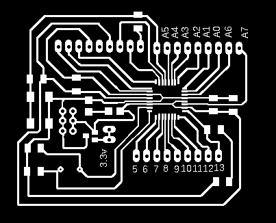
Open the PNG file in Paint and work on it for the drill, border and traces as:

After that now it time to create the rml file for this I use the Fab Mods as:
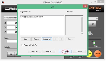
After generating RML, sent both files to Rolan monoFAB SRM-20 machine and follow below steps.
* Place PCB on machine bed
* Open VPanel for SRM-20 in Desktop
* Select the machine, in our case it is Roland SRM-20.
* Change the Drill bit for traces 1/64 and for drilling and cutting 1/32.
* Now there are few details that we need to input, we can see those details from the images given below.
* Select the origion to x/y and z axis by changing values fo x, y and z axis from where it should be start.
* Adjust drill bit until it touches PCB board.
* Change Z-axis value little bit to dig PCB board slightly, then select new value of Z-axis as origin.
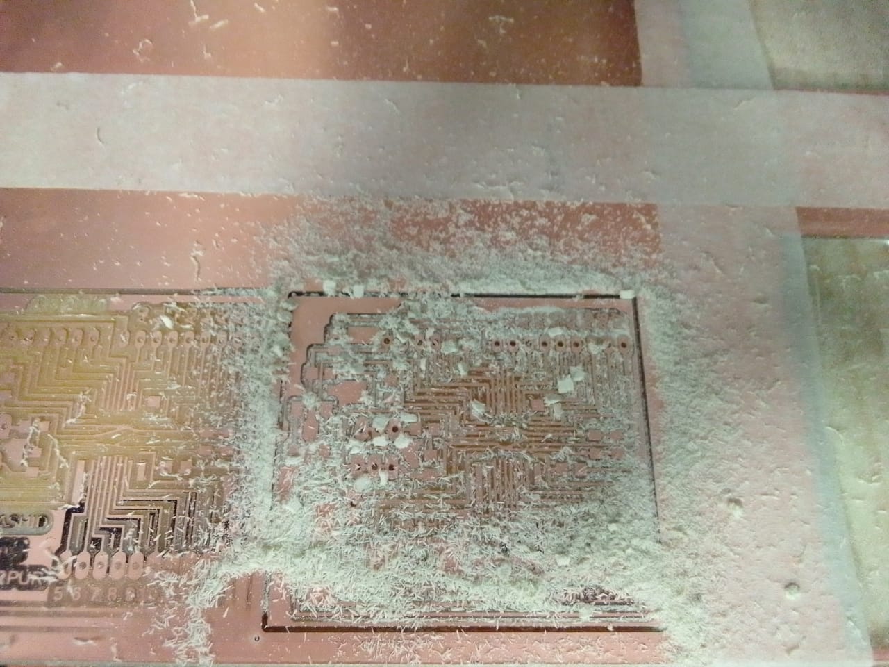
The Srm 20 Machine use for the milling.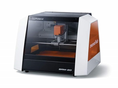
After Milling: