Group Assignment
Measure the power consumption of an output device.
In this week we decided to find the power usage of motor drivers on various DC motors.
On that initiative, we take current measurements and voltage measurement then on basis of that we find the total power consumption.
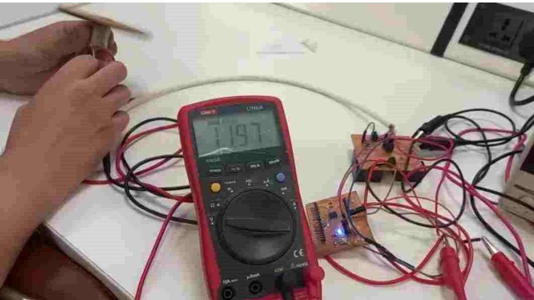
voltage reading.
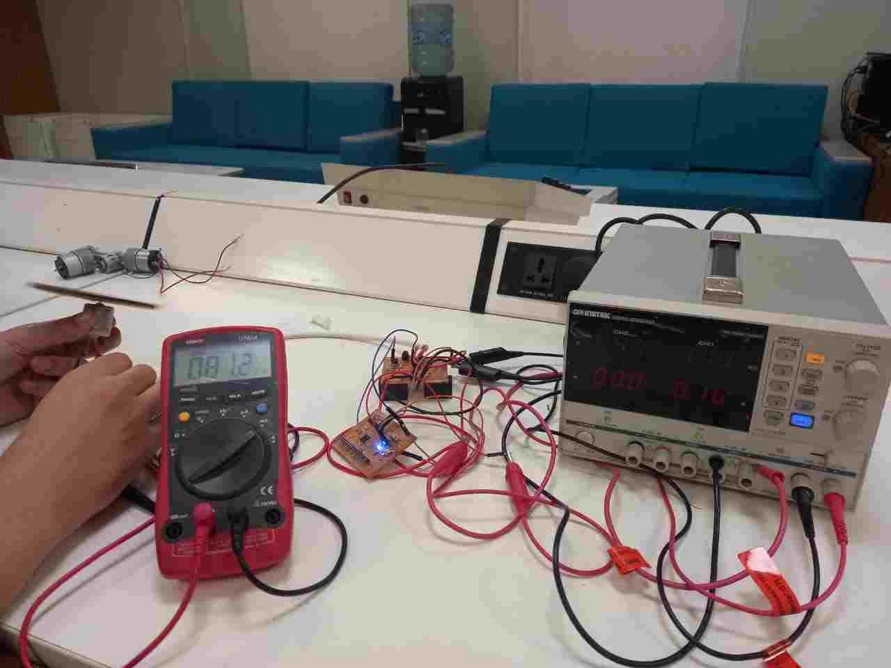
Current reading.
First we find the power consumption of the simple dc motor. we find that the current drawn by the simple Dc motor is 89.2mA. And the votage is as 11.98 Volt. As given in video.
As we know that the power =Voltage * Current
so Power consumption = P= 11.98V * 89.2mA
P=1.068Watt
After that we also find the power consumption of the Dc gear Motor. We find that the current drawn by the Dc gear
motor is 165.4mA and the given voltage is same as 11.98 as given in video.
As we know that the power =Voltage * Current
so Power consumption = P= 11.98V * 165.4mA
P=1.98Watt
Individual Assignment
ADD AN OUTPUT DEVICE TO A MICROCONTROLLER BOARD YOU HAVE DESIGNED AND PROGRAM IT TO DO SOMETHING
In this week, I want to make the the water level indicator by using the Circuit board (saksha Kit). That I design in the
input week and also I will use in my final project. I decide to make the water level indicator as I will have to make the sanitizer level indicator in my
in my final project.
For this I use the following Components:
* WATER LEVEL INDICATOR
Level sensors are used to detect the level of substances that can flow. Such substances include liquids, slurries,
granular material and powders. Level measurements can be done inside containers or it can be the level of a river or lake.
Such measurements can be used to determine the amount of materials within a closed container or the flow of water in open channels.
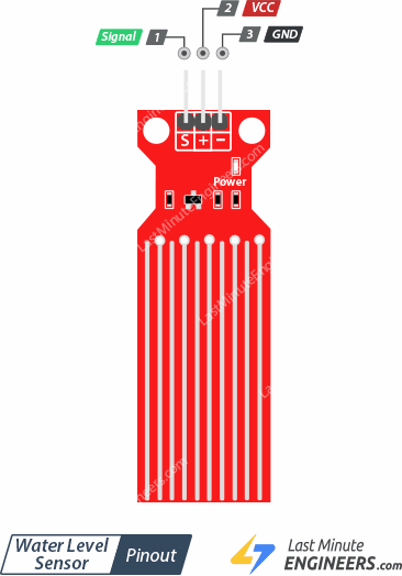
water level indicator.
* 2*16 LCD
An LCD is an electronic display module that uses liquid crystal to produce a visible image. The 16×2 LCD display is a very basic
module commonly used in DIYs and circuits. The 16×2 translates o a display 16 characters per line in 2 such lines.
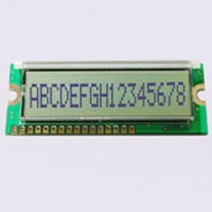
2*16 LCD .
* MICROCONTROLLER BOARD
For this week I use the satsha Kit as microcontroller that I designed in the Input Week.
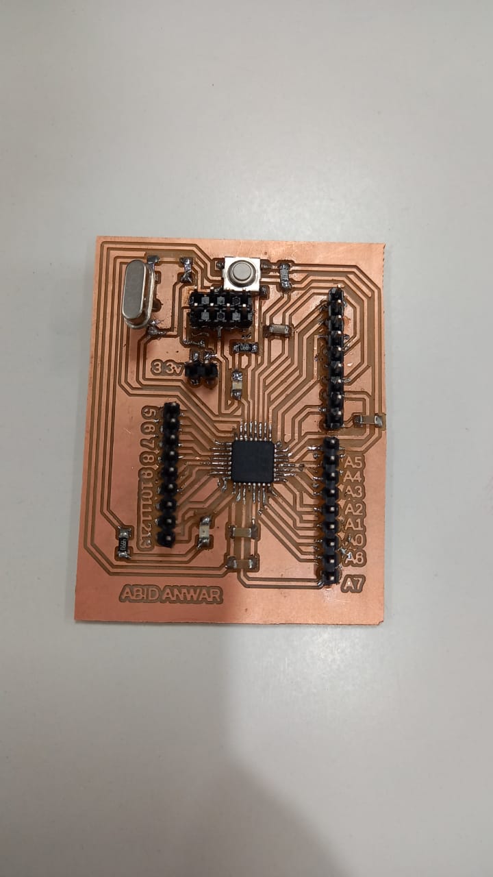
Satsha Kit .
*POTENTIOMETER
A potentiometer (also known as a pot or potmeter) is defined as a 3 terminal variable resistor in which the resistance is manually varied to
control the flow of electric current. A potentiometer acts as an adjustable voltage divider.
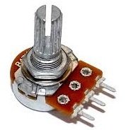
potentiometer .
Beside these components I also use the Jumper wires and breadboard for the connection.
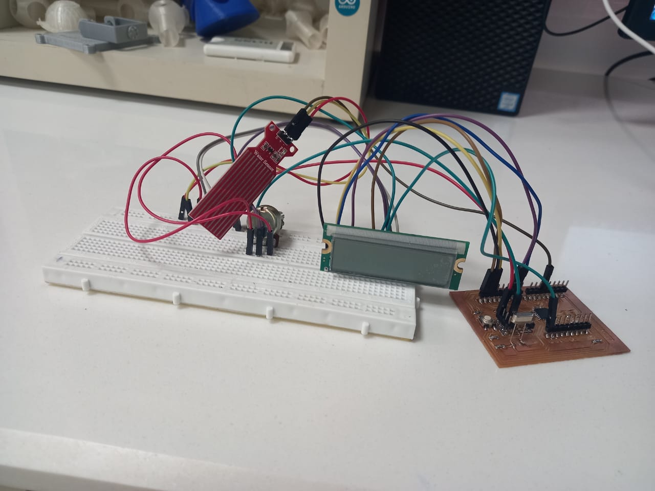
The circuit after connection .
PROGRAMMING
For Uploading program on board I use the FTDI cable and connect with the computer. And progarm in the
arduino as when the sensor sense no water the lcd will show as " The water level is Empty " and then after when sensor is slightly drip in
container and when the lower part of the sensor sense the water the Lcd will shows The Water level is 10% Full and this process proceed upto
when the sensor is fully drip into the container the Lcd will shows " The water Level is 100% Full" the code is as under :
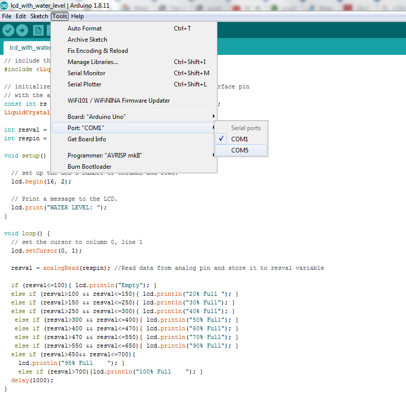
selecting the port.
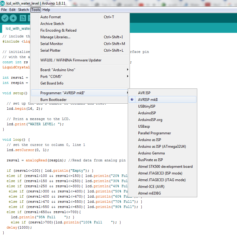
selecting the progarmmer .
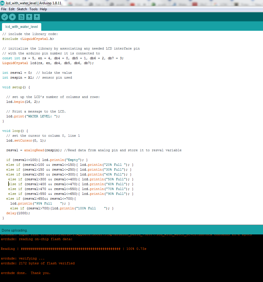
uploading code succesfully.
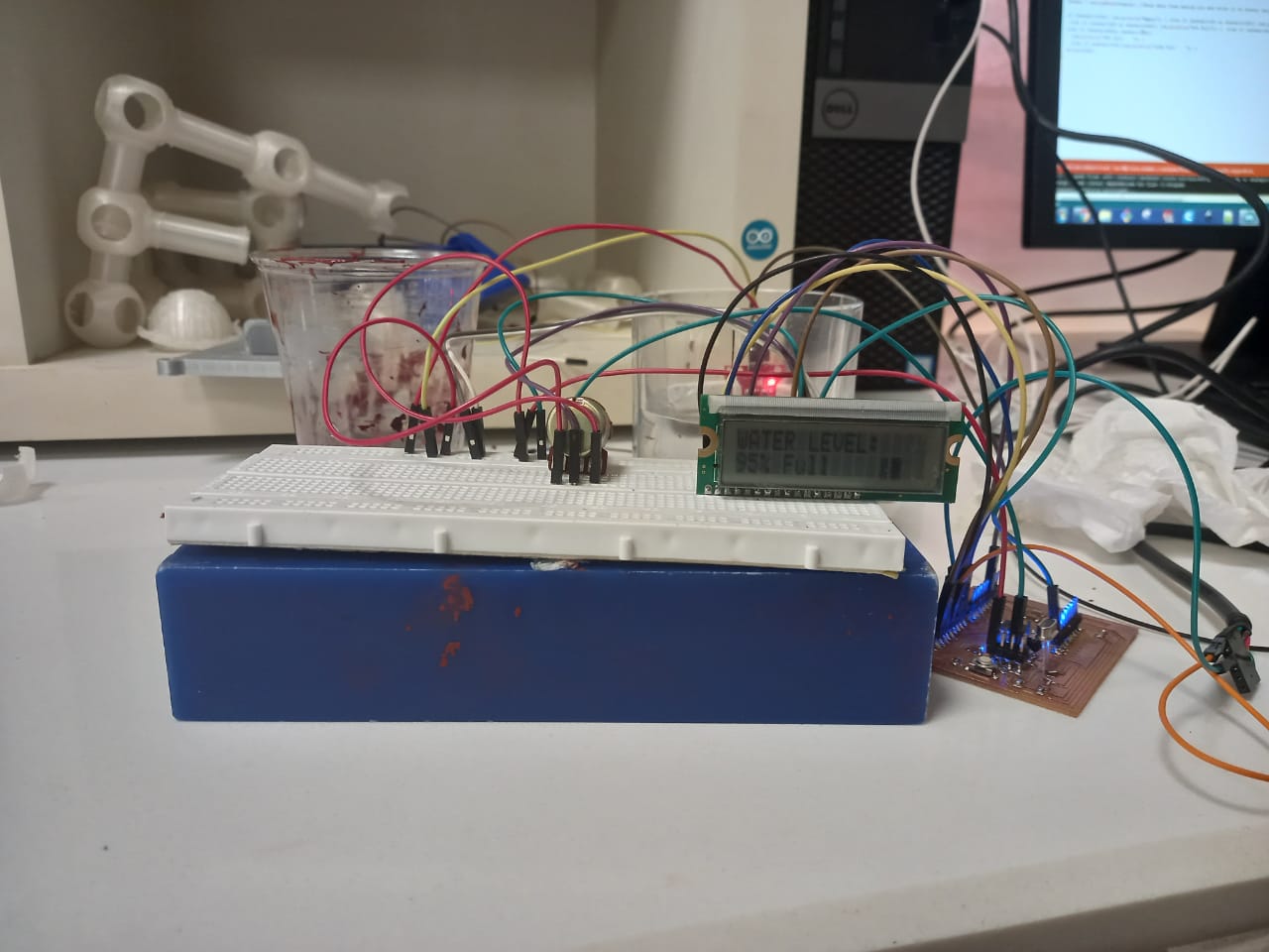
After succesfully uploading the code.
Coding Description
The main idea of the programming is that the Lcd and sensor is connected to controller and the lcd shows the level of water on the screen accordingly as the sensor sense the level of water on
the Bottle
Fist line in the picture of the programming shows the Library that I add for the working of the LCD as it is necessary to add this Library for proper work of the LCD.
I define the pin for controller to be connected as 5, 4, 1, 2, 3, . then I define the A1 Pin for the sensor mean that the sensor will be connected to the Pin A1 and give the initial value as resval=0. After that I
define the LCD To Print the Water Level Empty
if there is value of resval is less than 100. Here the sensor have portion which sense the water and give signal to the e microcontroller accordingly.
For the output on the LCD I define the level of the water as:
If the value of resval is greater then 100 and less or equal to 150 . The LCD should show the output as "The Water level is 20% full".
If the value of resval is greater then 150 and less or equal to 250 . The LCD should show the output as "The Water level is 30% full".
If the value of resval is greater then 250 and less or equal to 300 . The LCD should show the output as "The Water level is 40% full".
If the value of resval is greater then 300 and less or equal to 400 . The LCD should show the output as "The Water level is 50% full".
If the value of resval is greater then 400 and less or equal to 470 . The LCD should show the output as "The Water level is 60% full".
If the value of resval is greater then 470 and less or equal to 550 . The LCD should show the output as "The Water level is 70% full".
If the value of resval is greater then 550 and less or equal to 650 . The LCD should show the output as "The Water level is 90% full".
If the value of resval is greater then 650 and less or equal to 700 . The LCD should show the output as "The Water level is 95% full".
If the value of resval is greater then 700 . The LCD should show the output as "The Water level is 100% full".