KERF TEST
In this week we have to work on laser cutter, so first of all we need to characterize few things of our laser cutter. Number one is Kerf. When laser burn the material, the thickness or area of material which burn away are called kerf. The area/thickness may vary.
In order to measure the kerf of our laser cutter, we have designed test file in INKSPACE. Firstly we have measured the thickness of our material then we have made rectangular boxes of different thickness with 0.05mm difference around the actual thickness of material. we have cut one long slit of same height. Idea is to check which hole is perfect fit for that slit so that we can use that thickness.
MEASURING THE THICKNESS

Screen shot showing the thickness of the sheet.
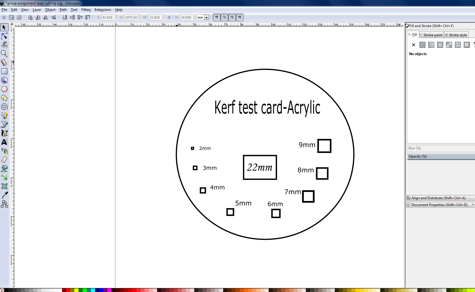
WORKING IN INKSPACE
SETTING IN EPILOGER
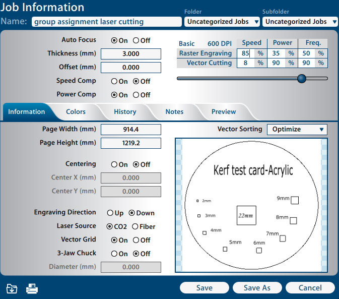
Screen shot showing thedifferent option in Epiloger.
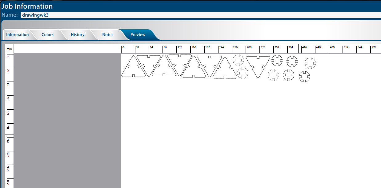
MACHINE READY TO CUT
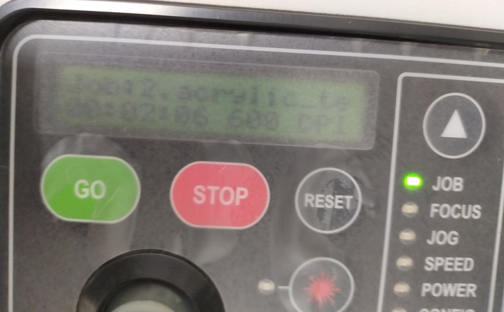
Screen shot showing that the machine received the command and ready to cut.
TESTING KERF IN DIFFERENT SLOT
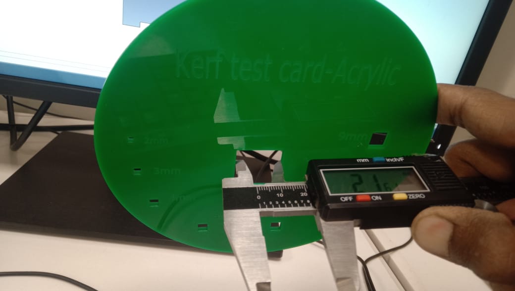
We measure the 22mm box using vernier caliper after laser cutting. Due to material burning during laser cutting, there is a 0.4mm gap.
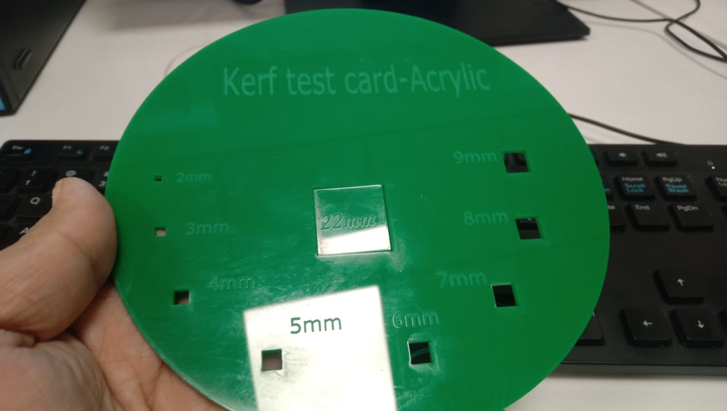
A 22mm piece of material is easily fitted into the kerf card box, which shows the laser's burning effect on material.
TEST CARD FOR POWER,SPEED,FOCUS,RATE
Similarly in order to test the power, speed, focus and rate we took the test from here. Edited it and then processed through epilog and cut it. We can see from below test card that changing the shades can effect in engraving. The darker the shade, the more it will engrave. Also it show the hole size, flexible cut and engraved writing.
TEST CARD FOR LASERCUTTER
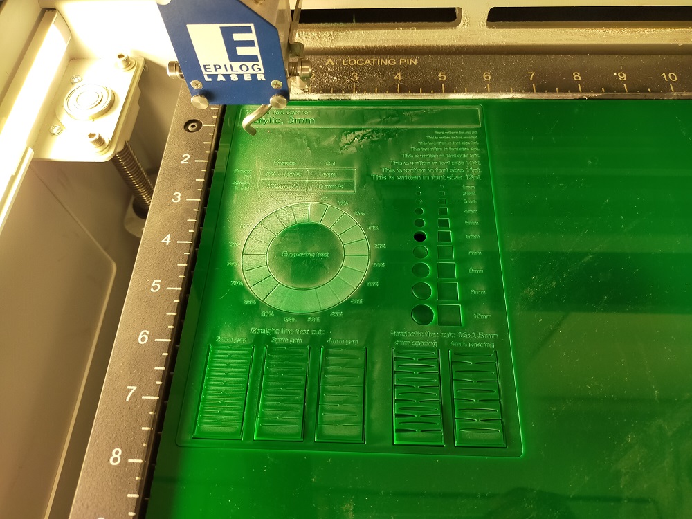
Screen shot shows the material test card for Acylic.
INDIVIDUAL ASSIGNMENT
cut something on the vinylcutter design, lasercut, and document a parametric construction kit, accounting for the lasercutter kerf, which can be assembled in multiple ways, and for extra credit include elements that aren't flat.
Requirement for this week is that design should be parametric. solidworks was more versatile, flexible and easy to handle so, I decided to choose solidwork. Solid works is parametric software and user friendly. I was new in solid work, I decided to construct the andriod mobile Phone as well tablet holder or stand. It will be very easy for everyone to watch any thing without holding tablet in the hand.
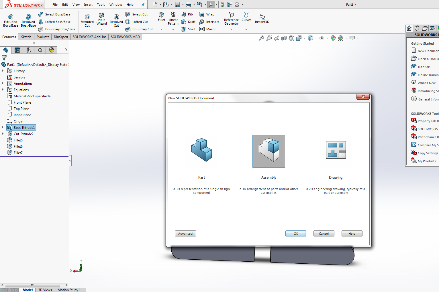
ENABLE THE EQUATION
To start working of parametric design in Solid work, first of all we need to enable the equation. Create variable of different name and assign them value.
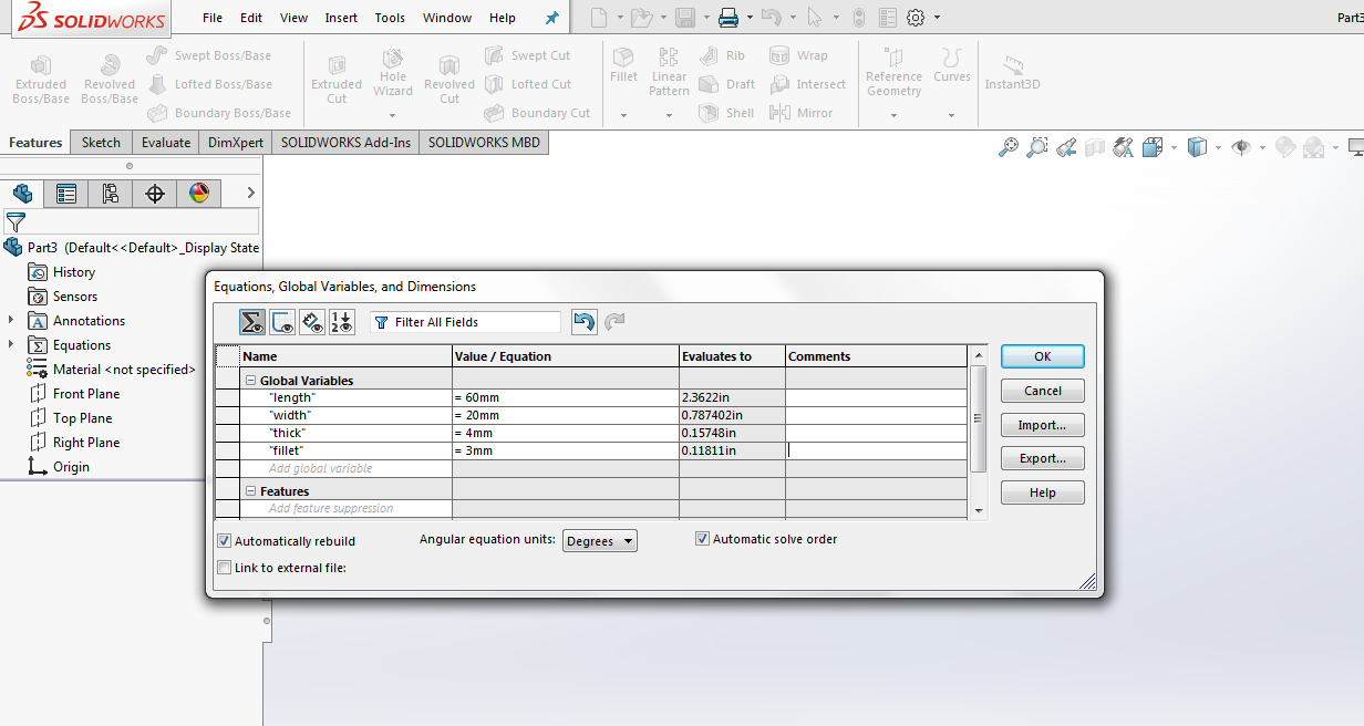
screen shot shows the equation given for the parts.
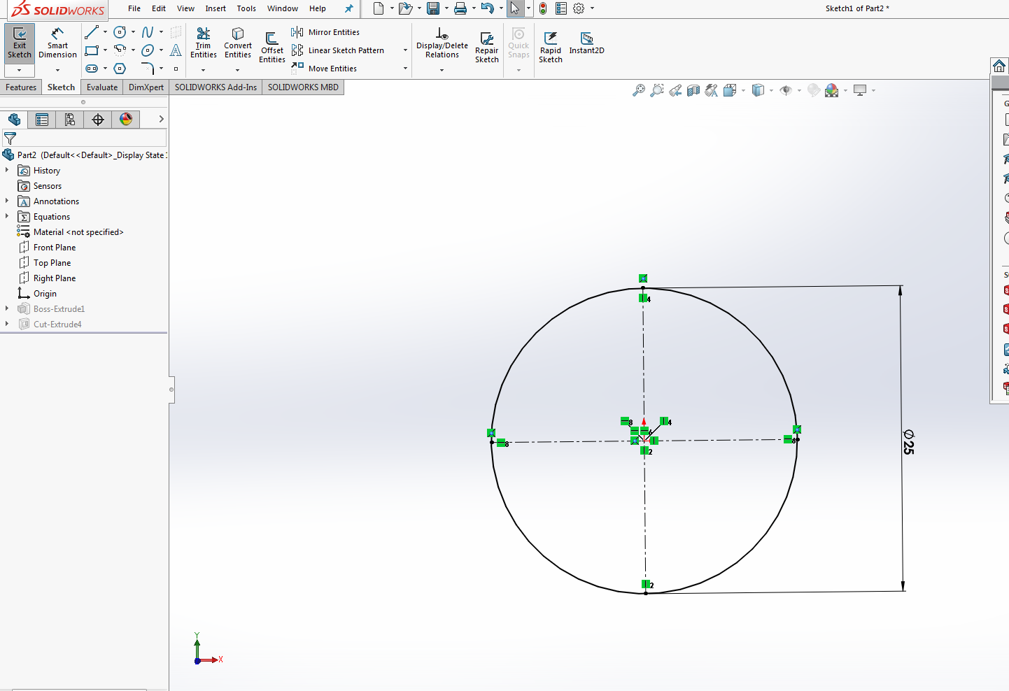
Drawing and giving global variable to the Design
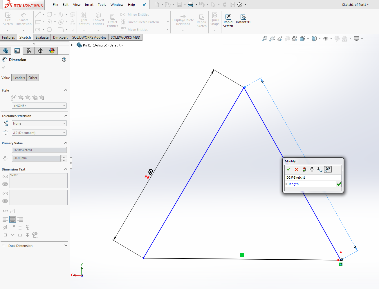
screen shot shows the drawing and giving value through global variable.
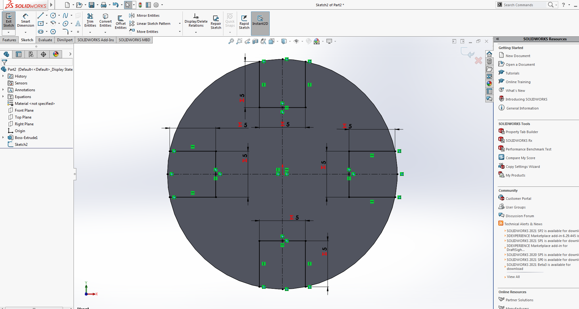
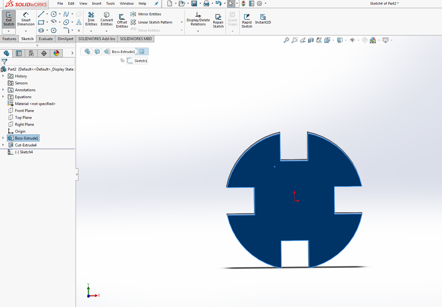
Extrude base and cut of the design
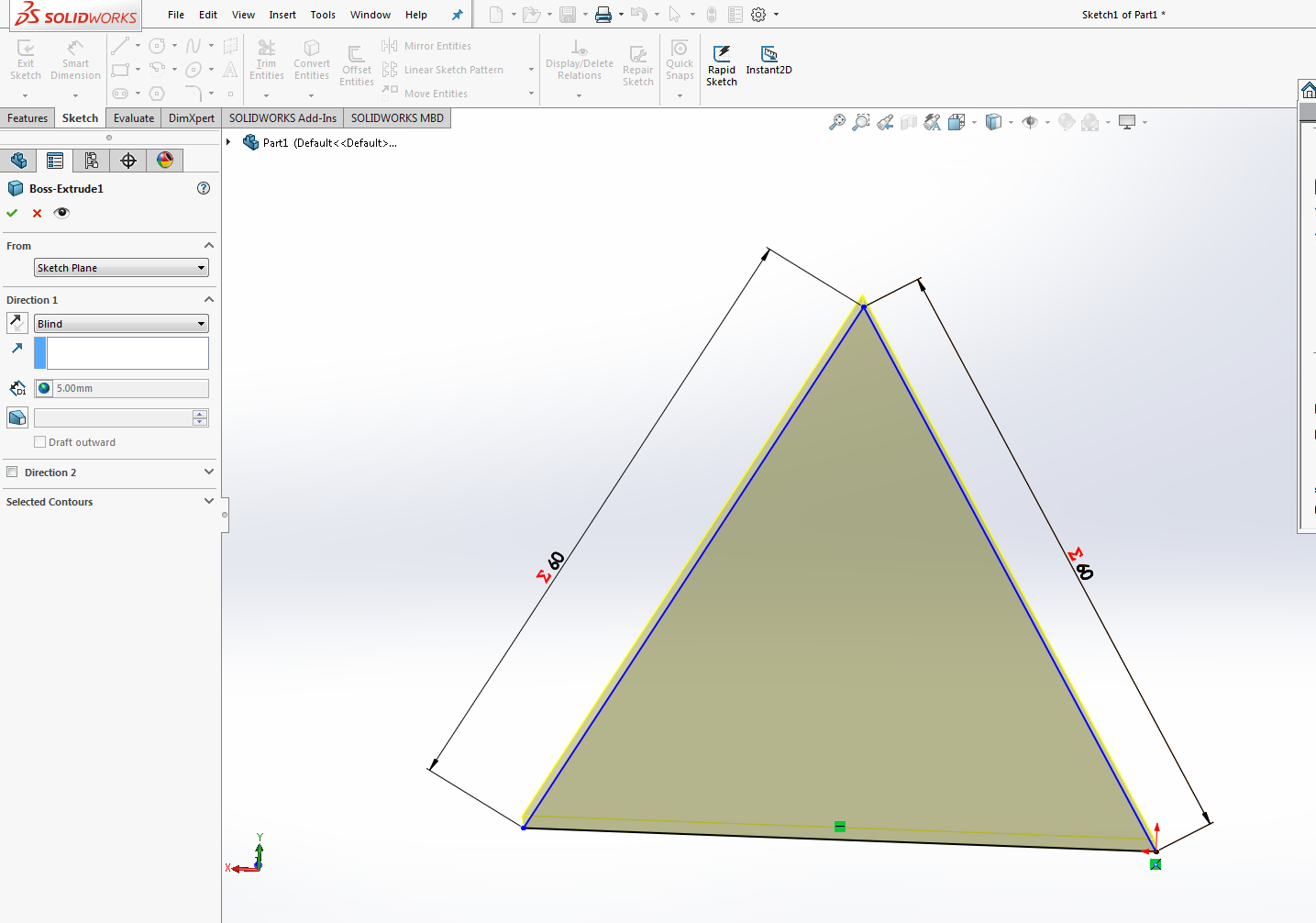
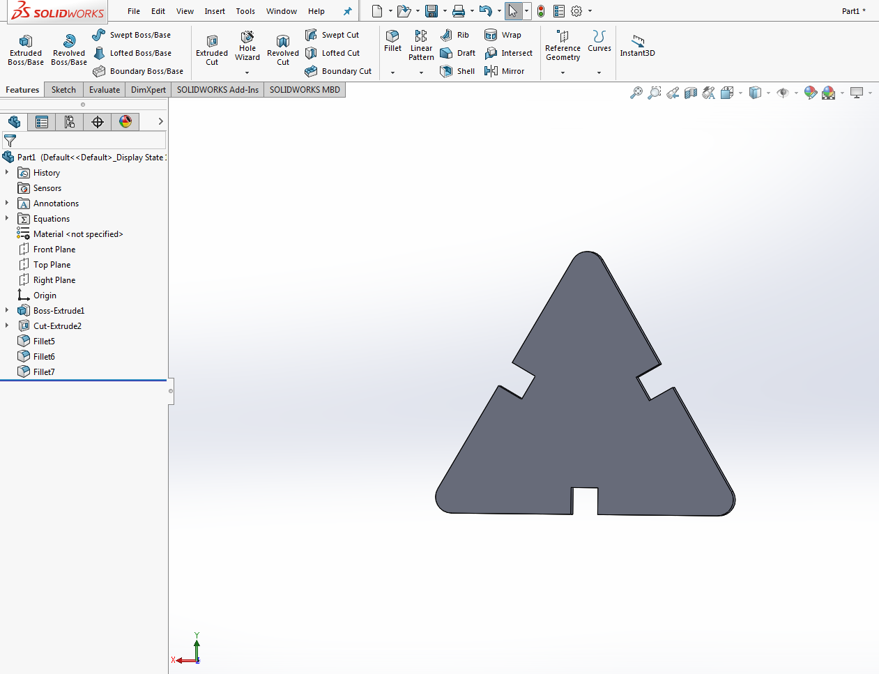
screen shot shows extrude base and cut for the design.
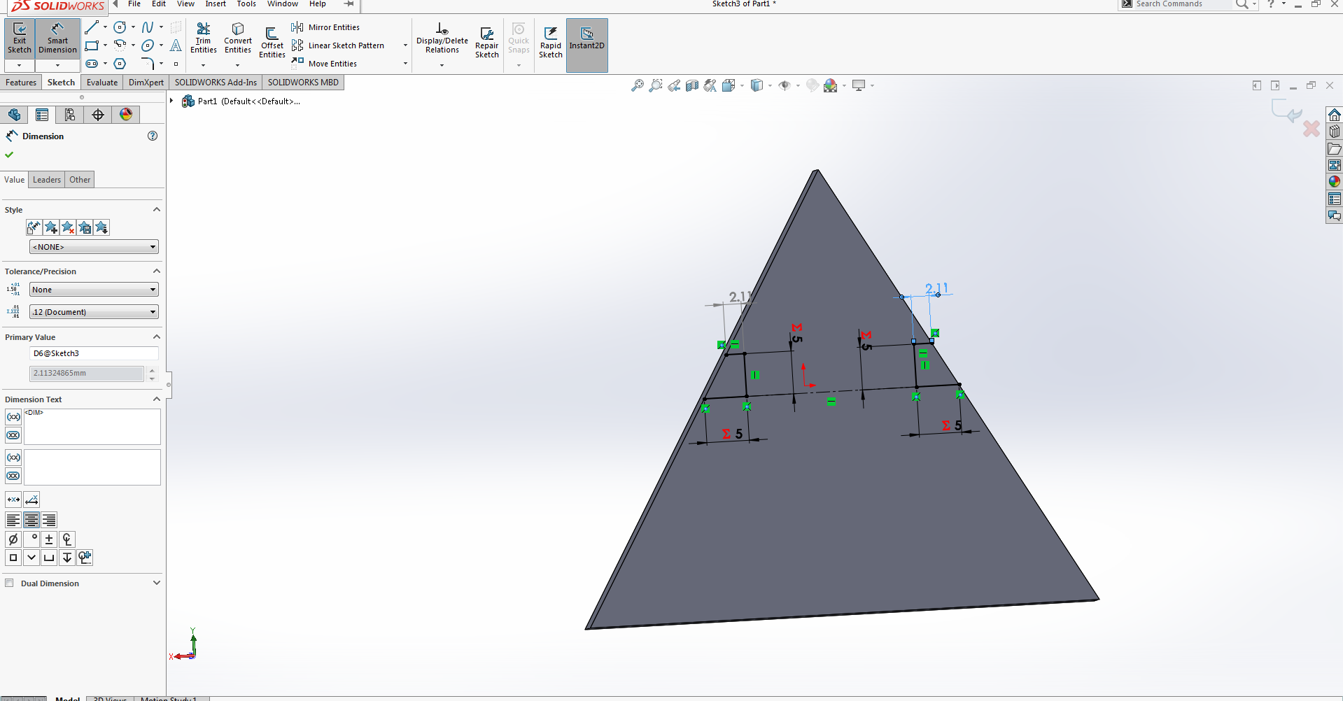
Drawing and designing the other part
screen shot shows drawing ,extrude base and cut for the second part.
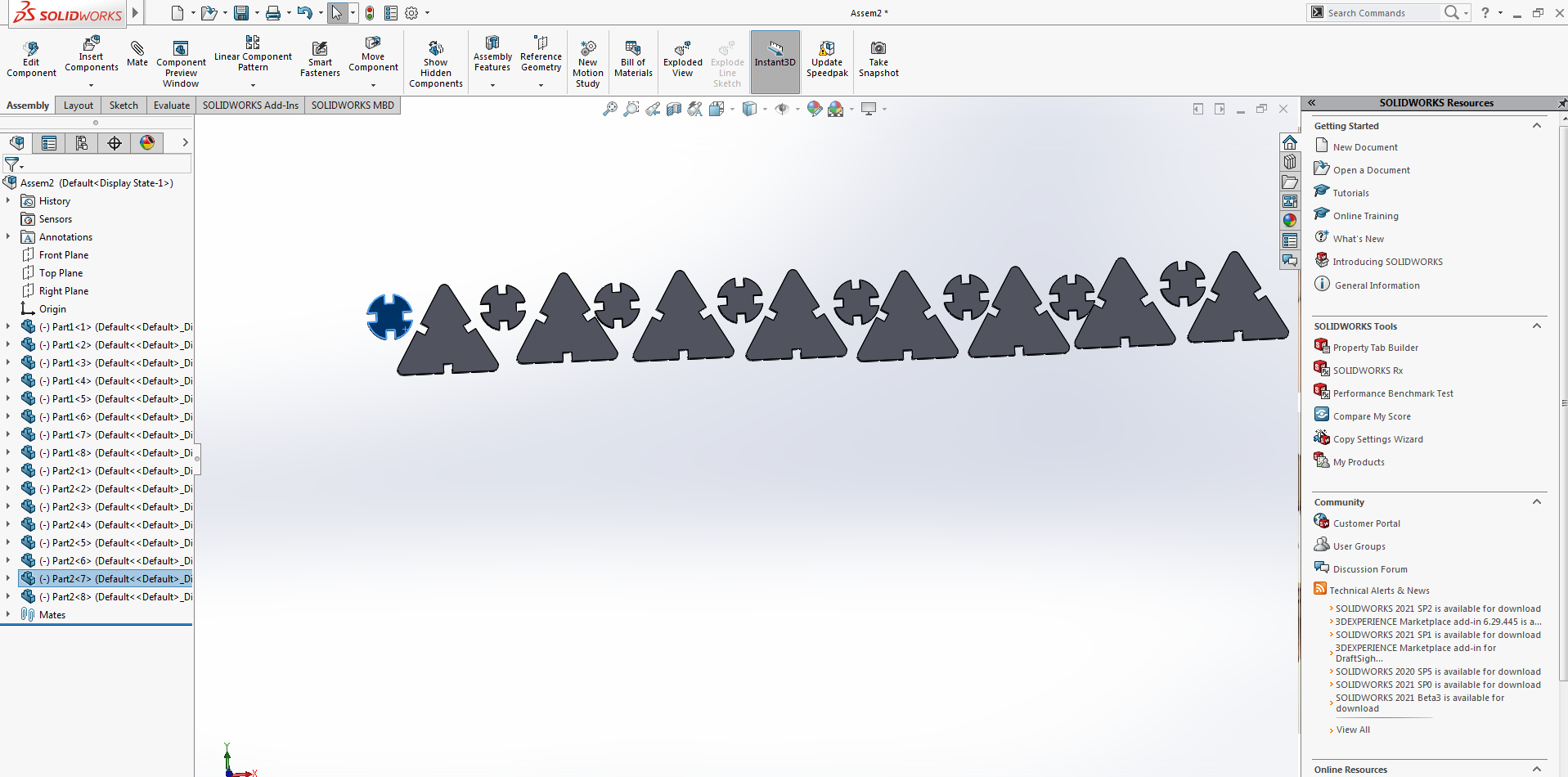
Assembling the parts
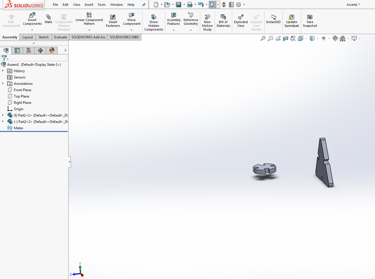
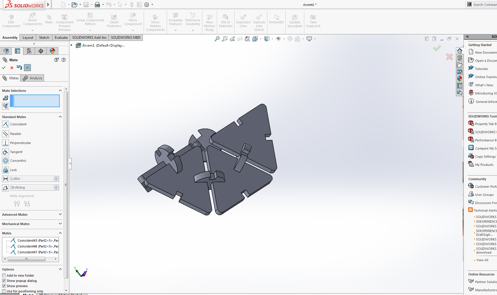
screen shots show the assembling of the parts.
Making drawing from assemble
For making drawing from the assemble select make drawing from the assemble at tool bar (file) and also selecting the 1:1 scaling.
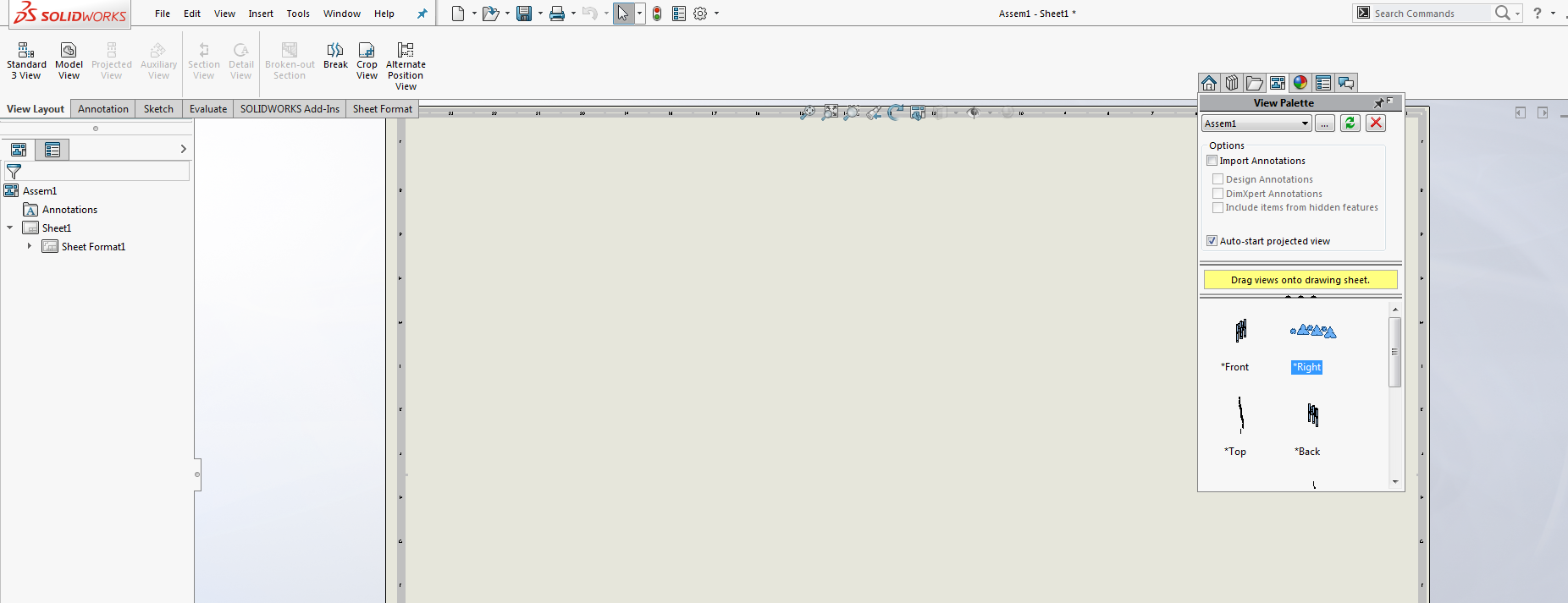
screen shots show the make drawing from the assemble.
Genarating the .dxf file
For generating the .dxf file select save as from the file toolbar and select .dxf file.
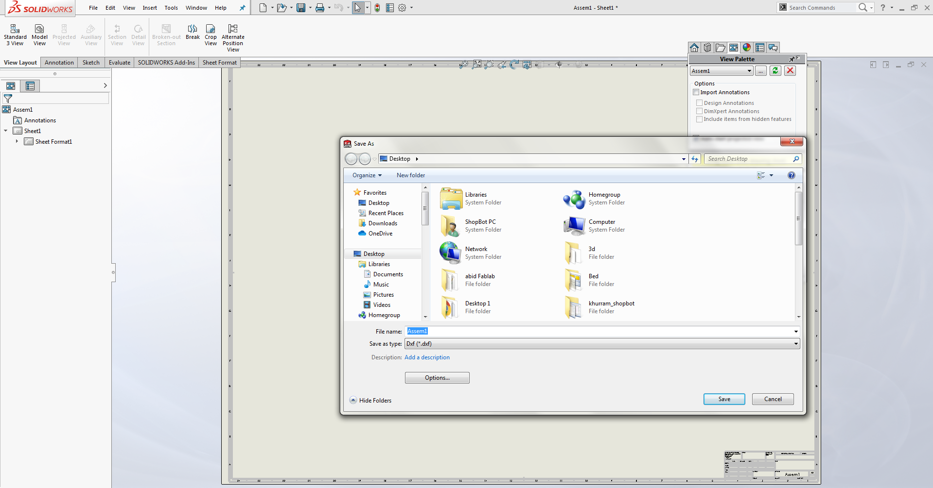
screen shot shows generating dxf file.
Opening the .dxf file in InkSpace
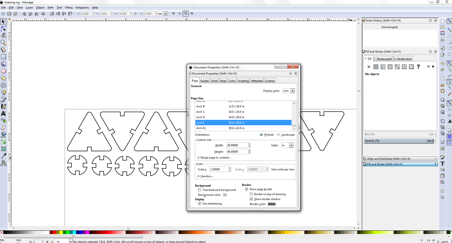
Setting the stroke and saving the file in Pdf format.
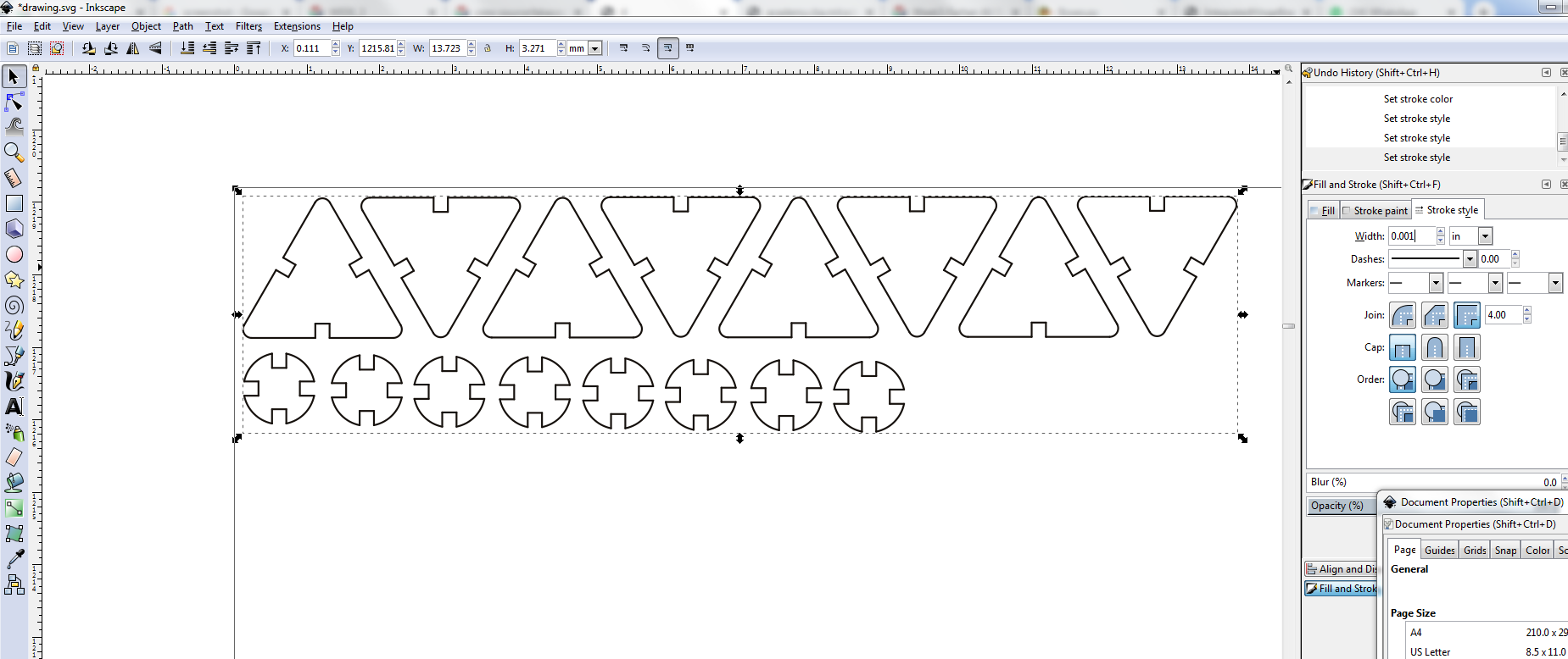
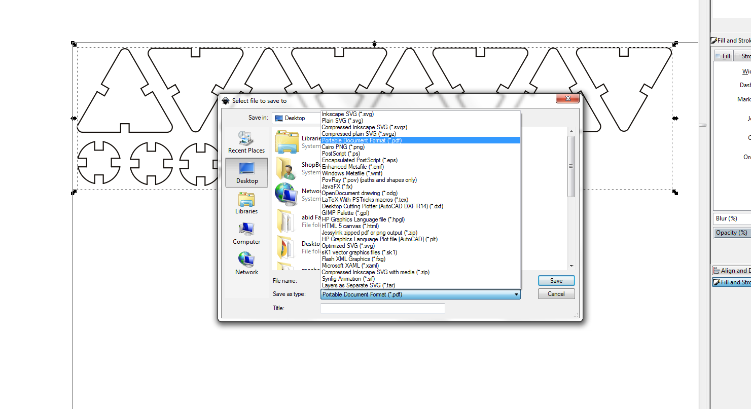
screen shots showing the stroke setting and saving in pdf format .
Working on Epiloger
After saving in pdf I open the file in epiloger and set the speed, power and Frequency.
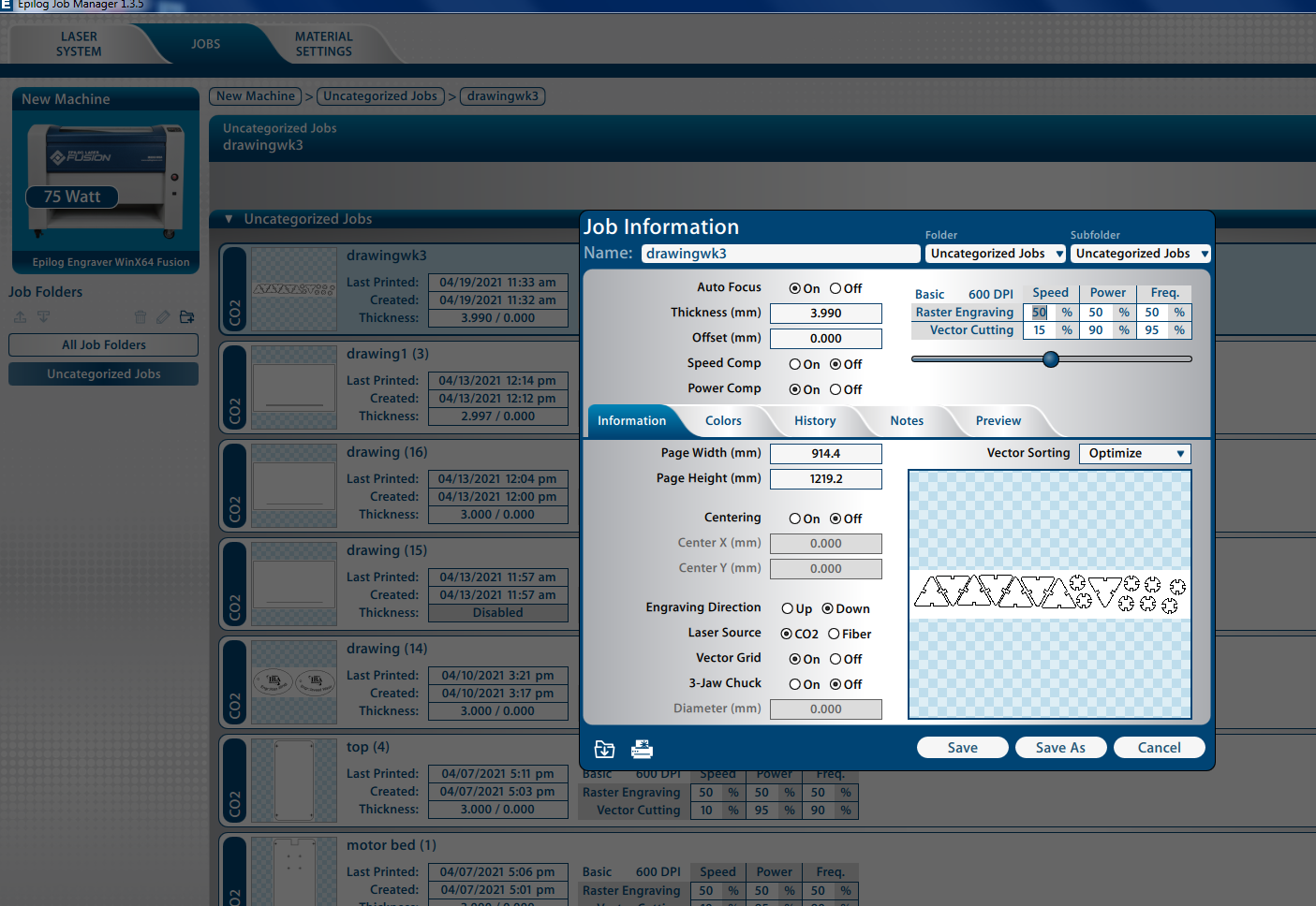
Screen shot of opening and setting in epiloger.
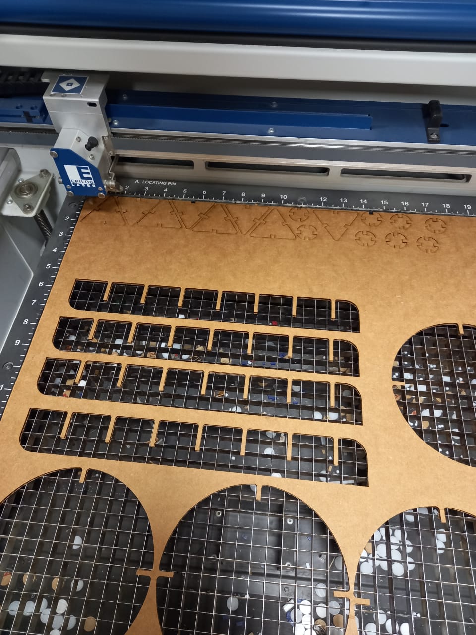
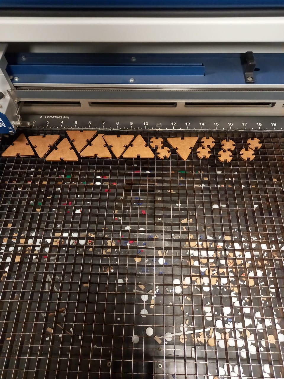
Screen shot of after laser cut
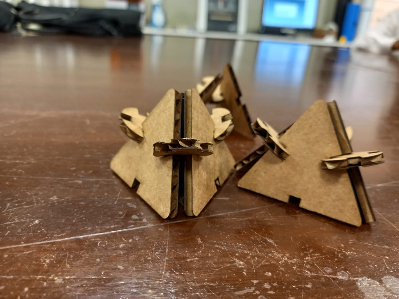
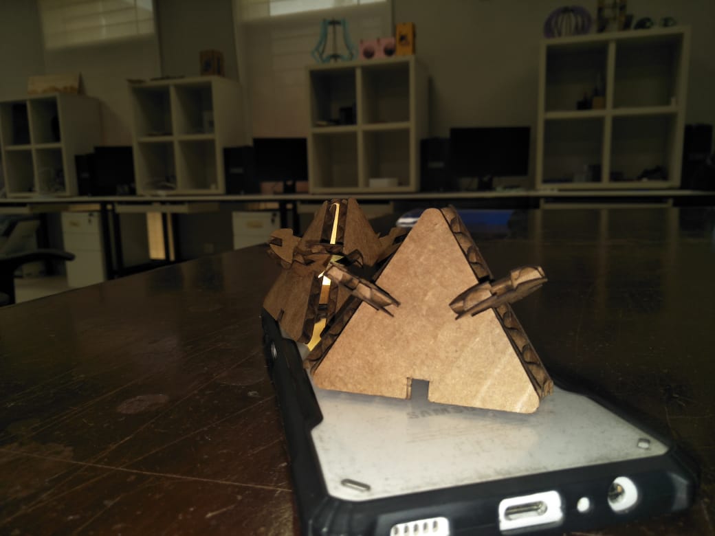
After Assembling the parts.
CUT SOME THING ON VINYLCUTTER
The second assignment of this week is to cut something on vinyl cutter.
I decide to cut the logo of FabLab Khairpur with My name.
OPEN THE INKSCAPE SOFTWARE.
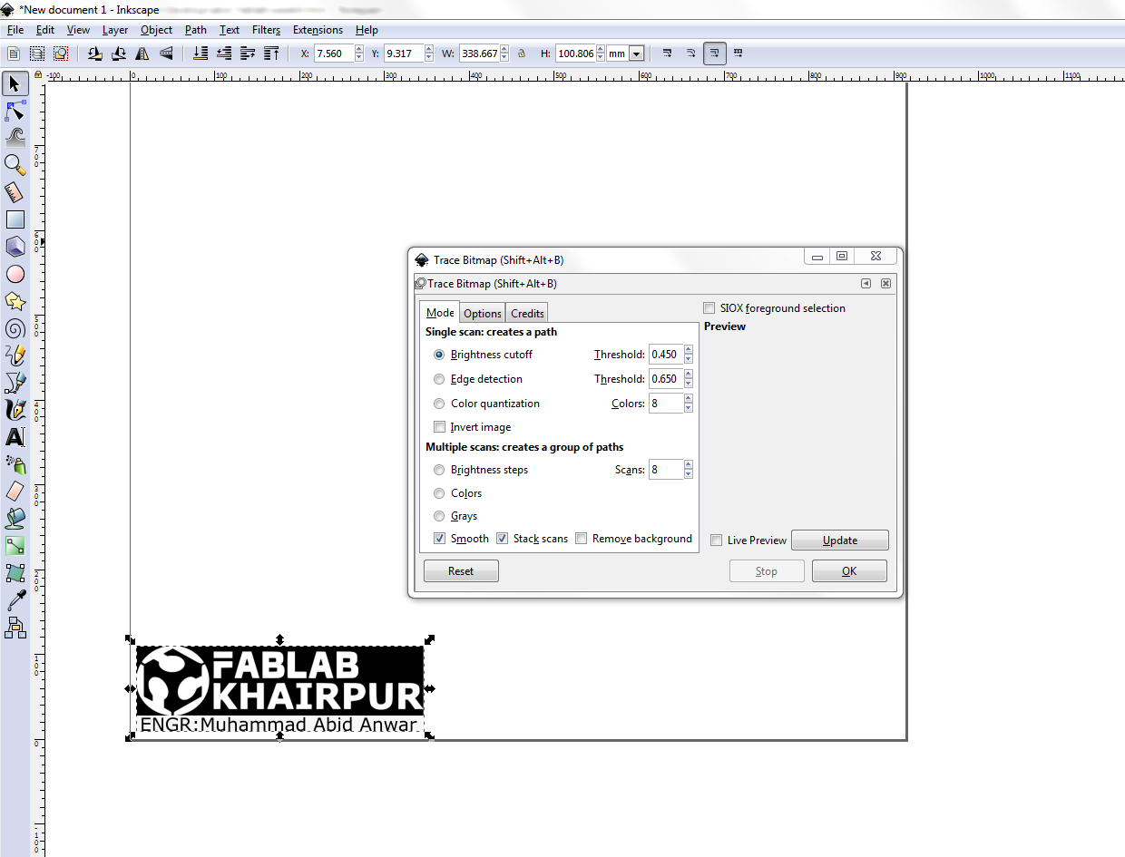
First of all I download the logo. I Open Inkscape software and import the logo. Go to "Path" and select the trace bit map.
Add a text of my name.
Select the brightness cutoff and adjust the threshold. Then remove the original picture and keep trace bit map logo.
Export as png
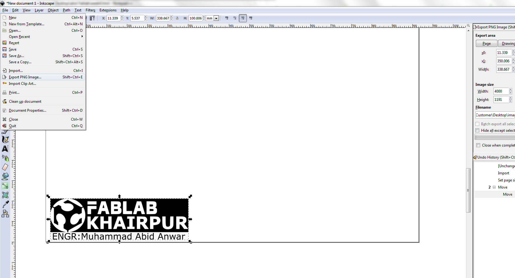
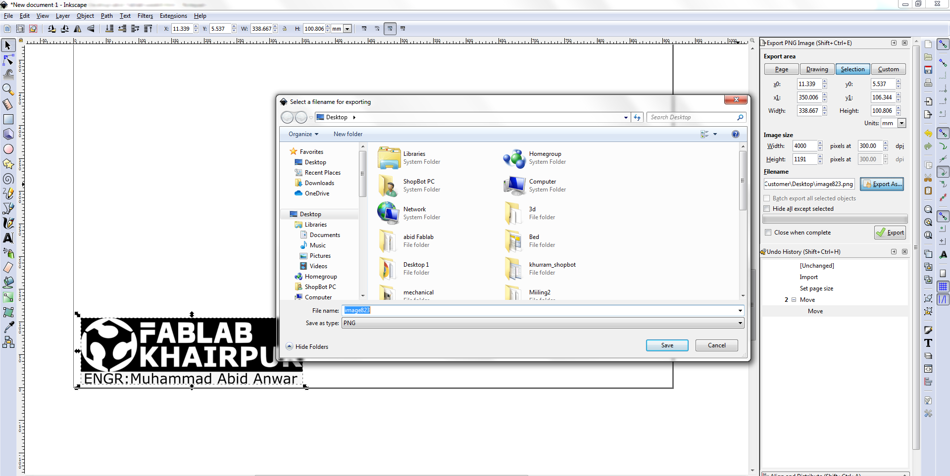
Screen shots showing the expont as png.
Open the png file in paint save as BMP
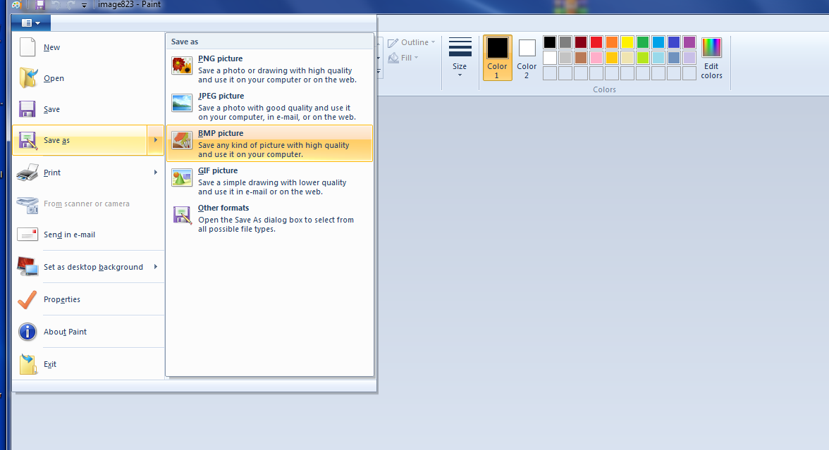
Screen shot showing the paint file savind as BMP for Cut studio.
CUT STUDIO SOFTWARE
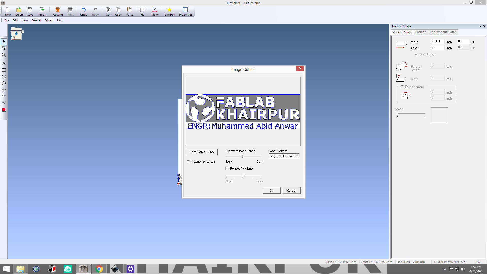
Screen shot of opening and seting for cutting in cut studio.
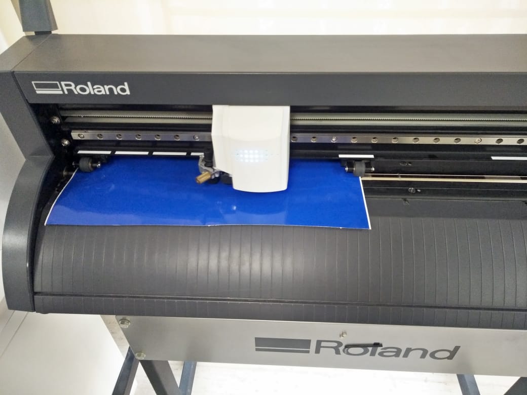
SHEET INSERTION
Before turn on the cutter we need to insert the sheet. While inserting the sheet it is important to remember that the roller that hold the
sheet will be in the white ribbons.
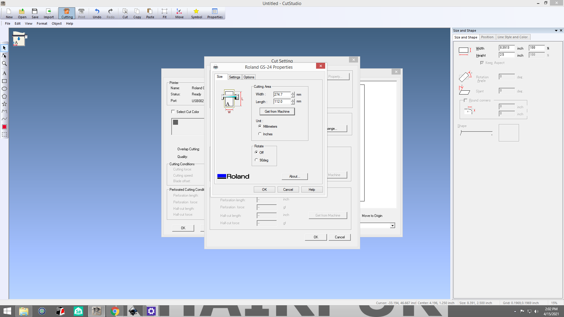
SHEET SETTING
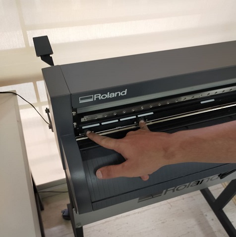
Figure showing the swith button and different option of paper size
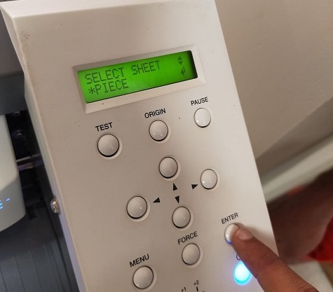
Figure showing the header which will calculate the dimension.
Removing the unwanted parts
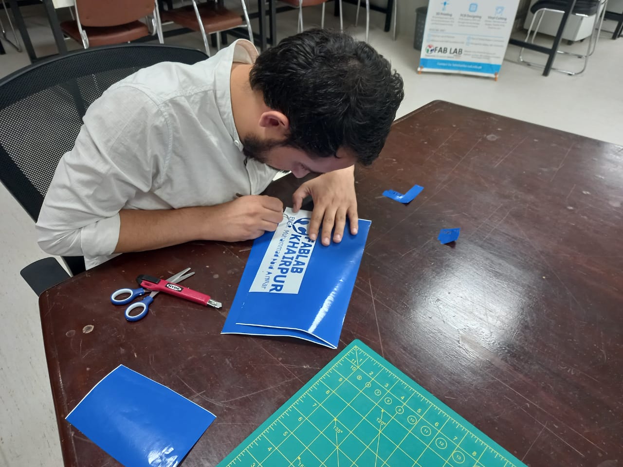
AFTER REMOVING UNWANTED PARTS
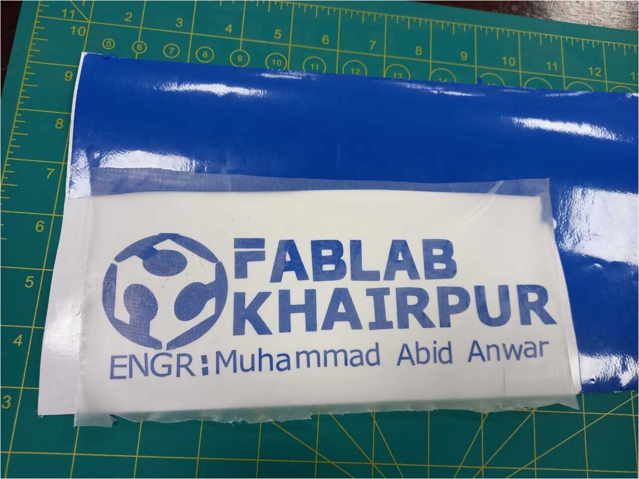
after removing the unwanted parts and applying the transparent for pasting.
PASTED STICKER
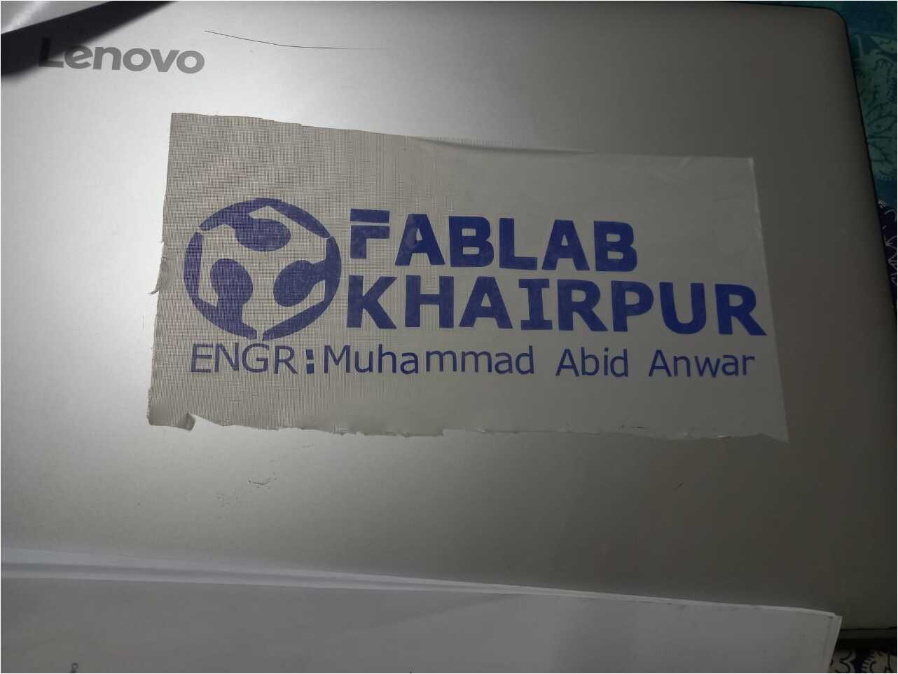
After apply the sticket on my laptop press the sticker with card and slowly remove the transparent tape.
FINAL RESULT
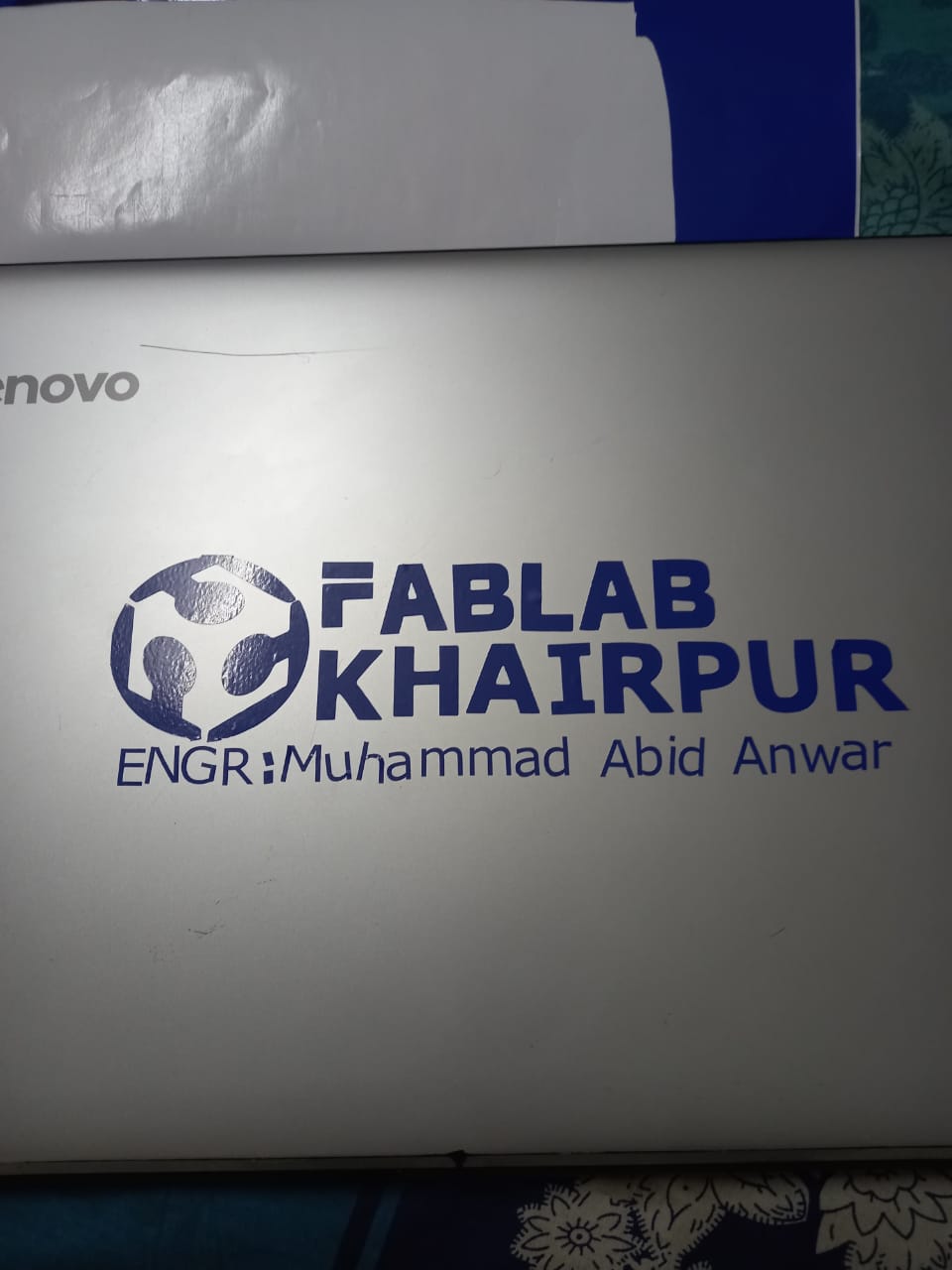
The final result after pasting on Laptop
Download all files from here