Week 6
Electronics Design
This week's aim was to understand and design circuit boards and process them. We started off by understanding the basic components in a circuit, what they are used for and how it is supposed to arranged. Though I have a little experience soldering components before, soldering such small sized components to the precision was quite challenging. I also got to use components ive never used before. This week was fascinating and got me exploring an area that I have always loved to explore.
Individual Assignment
The individual assignment for this week was to redraw an echo hello world board, add at least one button and an LED. I also have to check the design rules, make the board and program it.
I first started by arranging a few required components on Autodesk Eagle. Eagle was new for me, so i initially had some trouble figuring out how to use it. I dragged some components into the screen before starting to build the circuit.
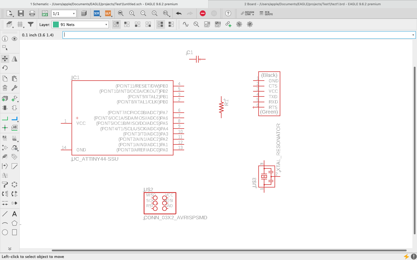
I then started arranging and then connecting the components using nets tool. This was getting easier as I continued using it. I had to rearrange it multiple times. The software is not too good, it's User Interface could be called okay but no the best one. But it was indeed a fun thing to learn.
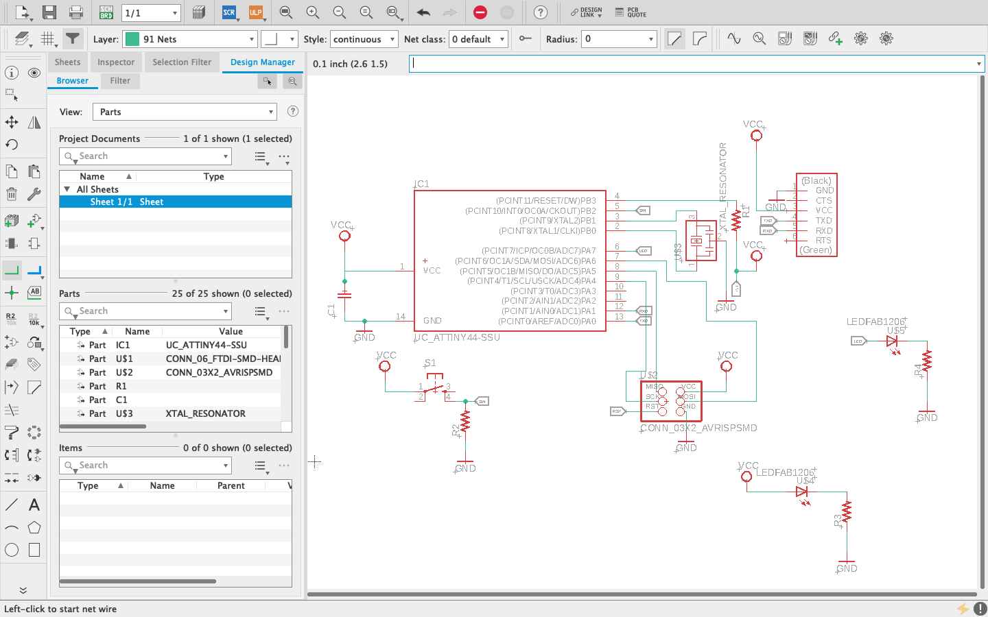
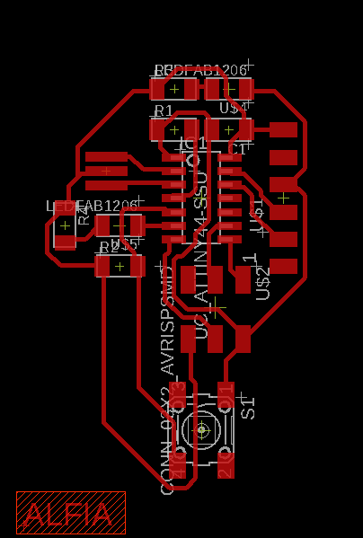
Once I happy with the schematic design I made and made sure the connections were fine and ensured all components were properly connected or rightly labelled, I went ahead to convert it to the board
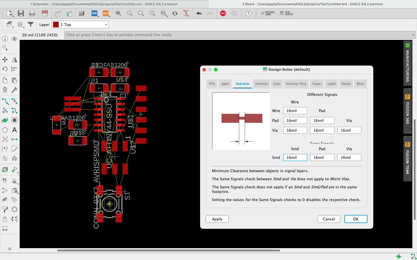
I then arranged the components on the board making sure there is no overlapping or crossing of connections. Once that was done, I autorooted the board. Initially there were a few connections that couldnt be completed. A few adjustments were made and then rooted again to give one connection that wasnt completed. I did a few changes and then rooted again to get the whole circuit done.
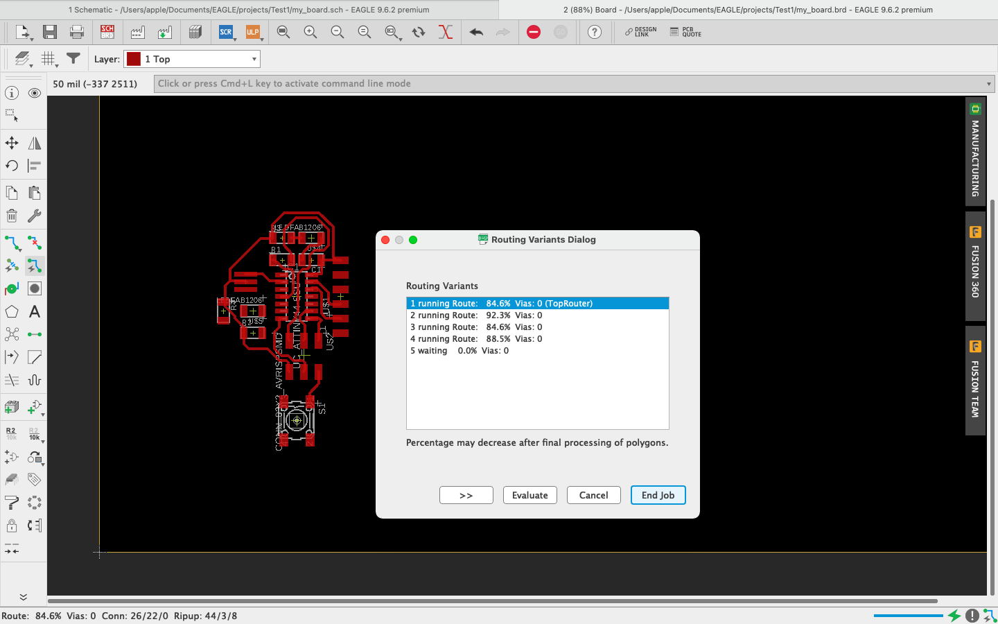
When all connections were done I saved the race of the circuit that is to be milled.
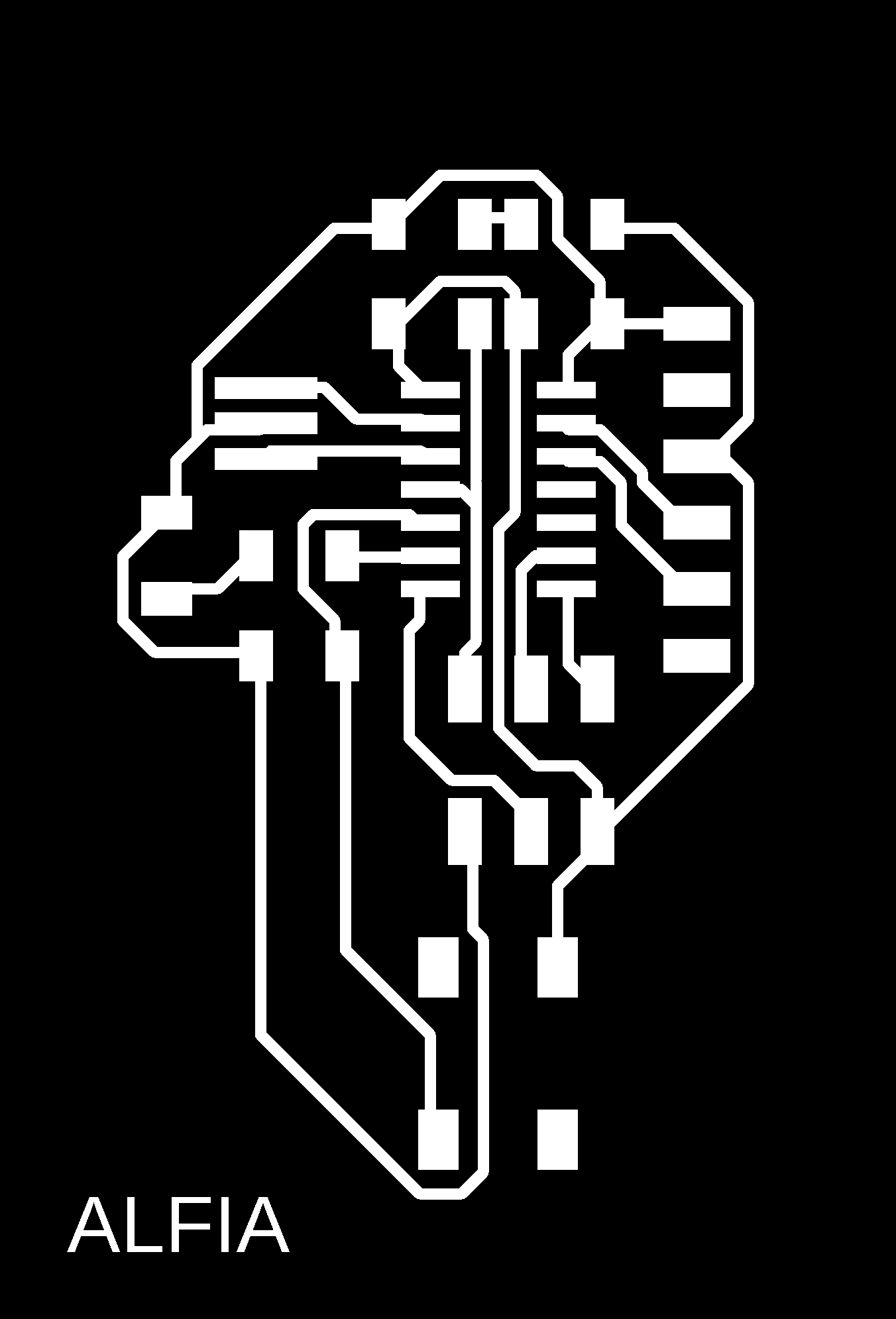
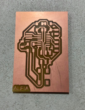
The next thing to do was to mill the board. I used mods to operate the PCB milling machine like always. I adjusted the origin and had my PCB milled. I initially didnt get the PCB milled properly, so I had to tighten the screw again after moving the bit to the center of the bed.
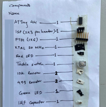
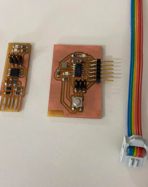
Now that my board was ready, it was time to assemble the components. I picked the components from the inventory room and started to solder. Since the board was tiny, it was slightly challenging to solder the components on to the board.
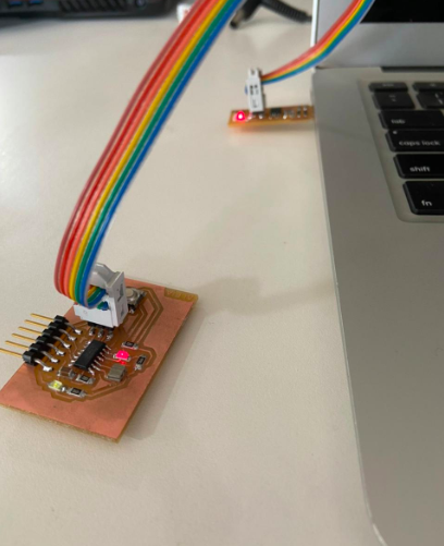
When soldering was completed, I was left with programming the echo board. I had added an extra LED and switch. So i decided to program it so that the LED blinks when the button is pressed. I used Arduino and the programmer I made earlier to program this echo board.
Programming with AVR DUDE
In the echo hello world examples had a sample programs. I wanted to try out how to program my board using AVR C. I tried to do it on my laptop, but the make file was not being formed for some reason. So i decided to learn with my colleague Saheen's Laptop. While at it, I learnt a few things about using Linux as well.
We first downloaded the file on his laptop from the academy documentation page.
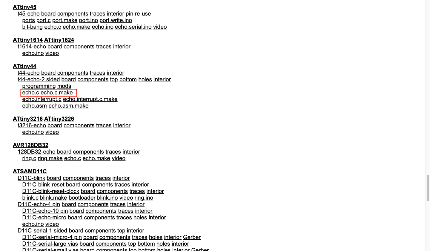
Then moved both file into a folder and opened in visual studio code then renamed the 'echo.c.make' to 'Makefile'. Then moved both file into a folder and opened in visual studio code then renamed the 'echo.c.make' to 'Makefile'
Screenshots of the C programming has been taken from Saheen as I was helped by him and used his laptop.
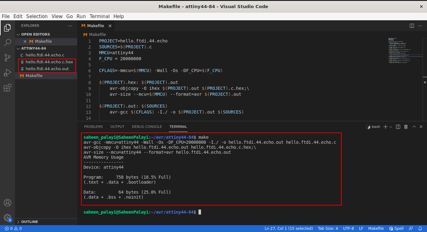
Then in the vs code terminal we entered 'make' that created the .out and .hef files to program from the source file echo.c . In the make file there were many codes which were pre written. Saheen helped me find the codes for the FABtiny ISP, We just had to type them with the make command in the terminal after plugging the ISP and attiny44 echo hello hello-world board.
We then plugged in the board and entered the command 'make program-usbtiny' in the terminal. This worked perfectly fine on my board.
Programming with Arduino IDE
The below program was then uploaded to my board using the ISP
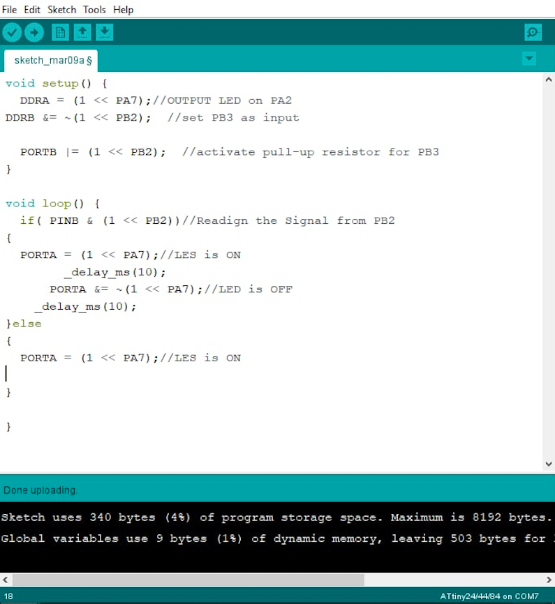
I then tested the board to see if it was working and it was!!
Group Assignment
This week's assignment was to use the test equipment in your lab to observe the operation.
FLUKE 101 Pocket Digital Multimeter
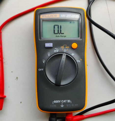
A multimeter is a tool for testing different parameters of an electronic circuit board. Here are the tests which can be conduced using a multimeter:
Voltage, Current, Continuity, Resistance, Frequency, Capacitance
Specifications:
V AC Range: 600.0 V
V DC Range: 600.0 V
Ohms Range: 40.00 MΩ
Capacitor: 100.0 μF
Frequency: 100.0 kHz
Size: 130 mm x 65 mm x 27mm
INSTEK GPD-3303D Power Supply
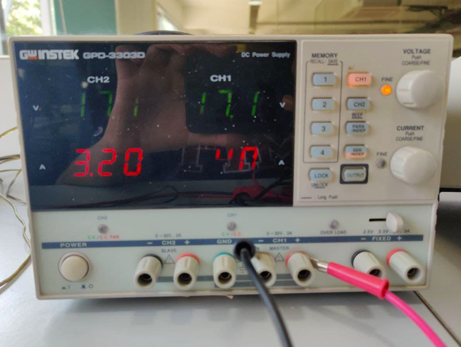
Instek GPD-3303D is a Multiple Output Programmable Linear D.C. Power Supply. The GPD-X303 Series offers digital panel control, large display, bright LED indicators, high output resolution, 4 sets of setup memory, USB remote control and smart cooling fan control. Additionally , the GPD-X303S Series provides easy operation , a wide selection of panel setting and operation.
Features:
2/3/4 Independent Isolated Output
4 LED Display Sets: 3 digits after decimal point
1mV/1mA(GPD-2303D/GPD-3303S/GPD-4303S)
100mV/10mA(GPD-3303D)
4 Sets Save/Recall
Output on/off
Tracking Series and Parallel mode
USB Standard Interface
Labview driver
UNISOURCE DS-1100 100 MHZ, 2 CH, Digital Storage Oscilloscope
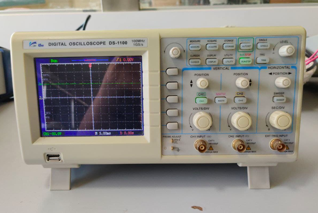
The digital storage oscilloscope is an instrument which gives the storage of a digital waveform or the digital copy of the waveform. It allows us to store the signal or the waveform in the digital format, and in the digital memory also it allows us to do the digital signal processing techniques over that signal. The maximum frequency measured on the digital signal oscilloscope depends upon two things they are: sampling rate of the scope and the nature of the converter.
Features:
100 MHz bandwidth, 1 M Memory
USB storage, RS232C & J45 interface
4000 point record length for each channel
Multi-waveforms math, FFT Function
Cursor & Track measurement
Waveform Record & Recall, Trigger Mode for Edge, Video, Pulse Width, Slope & Alternate
AFG-2100/2000 SERIES ARBITRARY FUNCTION GENERATOR
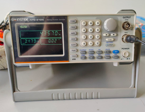
A function generator is a specific form of signal generator that is able to generate waveforms with common shapes. Unlike RF generators and some others that only create sine waves, the function generator is able to create repetitive waveforms with a number of common shapes. The AFG-2100/2000 Series Arbitrary Function Generator is a DDS (Direct Digital Synthesized) based signal generator designed to accommodate the Educational and Basic Industrial requirements for an accurate and affordable signal source covering the output of Sine, Square (Pulse), Ramp (Triangle), Noise and Arbitrary waveforms.
Features:
0.1Hz to 25MHz with in 0.1Hz Resolution
Sine, Square, Triangular, Noise and Arbitrary Waveform
1% ~ 99% adjustable duty cycle for Square Waveform
Waveform Parameter Setting Through Numeric Keypad Entry & Knob Selection
Amplitude, DC Offset and Other Key Setting Information Shown on the 3.5" LCD Screen Simultaneously
AM/FM/FSK Modulation, Sweep, and Frequency Counter Functions (AFG-2100 only)
PC Arbitrary Waveform Editing Software
The credits to the above details of the group assignment goes to my colleague Abhinav Ajith
Files
The schematic and board files can be downloaded.
The ino file can be downloaded from here