Computer-controlled Machining
WEEK 07
(14/03/2021 20:26 p.m.) Sunday evening. This week has become a little more enjoyable. After my frustrated attempts to try to program my Hello Piña! Board 😢, this week we have taken a little break in the electronics and programming assignments, and we have gotten detphly into the design and fabrication with the CNC milling machine.
This week has been very special! My crewmate Alberto and me have met in person all our Fab Academy crewmates that we are part of Fab Lab Leon. 😍😍
During this weekend we were able to work and enjoy the company of Mickaël, who came from Cuenca to Madrid to be able to do it the CNC milling assignment at the Fab Lab UE with us.
(13/03/2021 17:34 p.m.) In addition, on Saturday afternoon we were able to be in the Homelab of our crewmate Mauro, who gave us a CNC milling masterclass, gave us advice and showed us his machinery. It was very exciting!!🤩🤩
We regret that Sergio and our instructors Adrián, Nuria and Pablo, could not be with us this weekend together 😔. But in two weeks we will go to Leon! 💛💛💛 and I will finally be able to meet the full team. 😍
So, let's go for it! 💪💪
Since we have to regain some energy for the next few weeks to come, this week's song is the combination of two ones: Look Alive, Sunshine + Na Na Na (Na Na Na Na Na Na Na Na Na) by My Chemical Romance.
It's time to do it now and do it loud
Killjoys, make some noise! 👩🎤
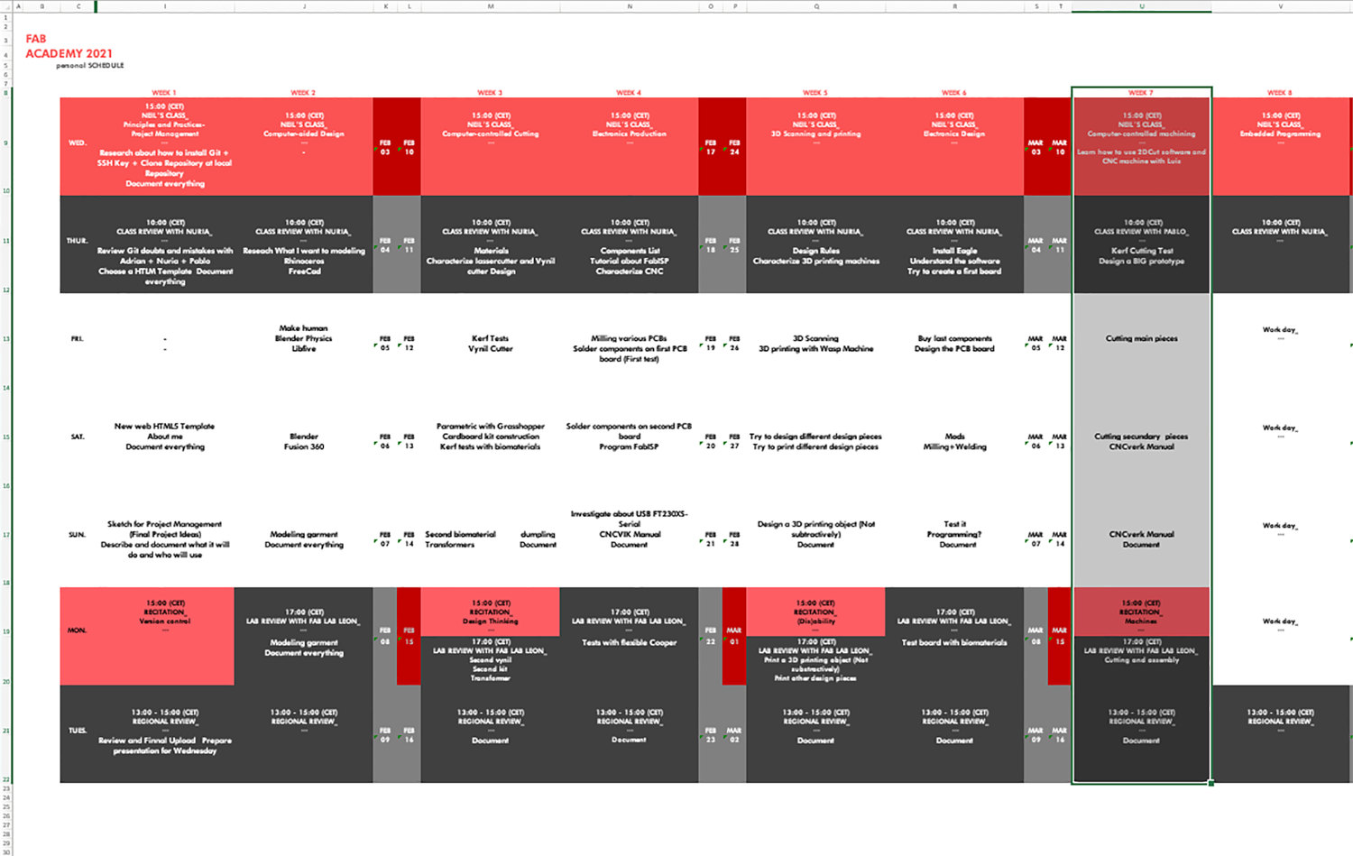
Organizing tasks
Once again we have two types of assignments, one's group and other individual. So as usual, I organize my schedule and here the following Evaluation Criteria that we have to approach to complete the Assignment:
- ✓ Do our lab's safety training
- ✓ Test runout, alignment, speeds, feeds and toolpaths for our CNC machine.
- ✓ Document our work and included our original design files
- ✓ Make (design + mill + assemble) something BIG
- ✓ Shown how we made something BIG (setting up the machine, using fixings, testing joints, adjusting feeds and speeds, depth of cut etc)
- ✓ Explained how you made our files for machining (2D or 3D)
- ✓ Documented what you have learned and explained the problems we had, how to fixed them
- ✓ Included our original design files
Extra credit
- ✓ Include a "hero shot" of our CNC designs
Group Assignment
CNC MILLING MACHINE
At Fab Lab IED Madrid we have a specific room where we have the big CNC Milling Machine located. The following model is:
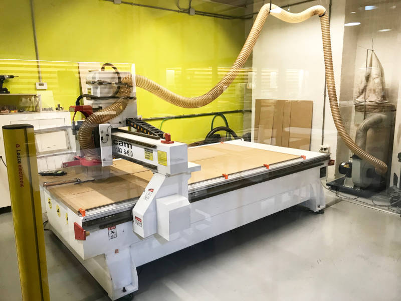
- Model: Milling Machine CNC TEC-CAM 1000
- Software: Cut2D (2D) + RhinoCAM (3D)
- Work area: 1300 x 2500 mm
- Bridge height: 180 mm
- Maximum thickeness of the material: Depending on the mill
- Materials: Acrylic, PVC, DM, solid wood, aluminum, copper, brass, porexpan, foam, etc
- SAFETY TRAINING
(10/03/2021 18:21 p.m.) After Neil's class, I started doing parts of the group assignment with Luis, one of the technicians from fab lab IED Madrid. The CNC is a machine that I have not used so much at the fab lab. And being such a dangerous machine, and when I was IED student, they did not teach us manipulate it. Only technicians and specialized personnel could send and prepare our files.
First of all I do is to identify the parts of CNC machine room. At the IED Madrid, this machine is in a separate room, glazed, to be able to see the milling work safely from outside.
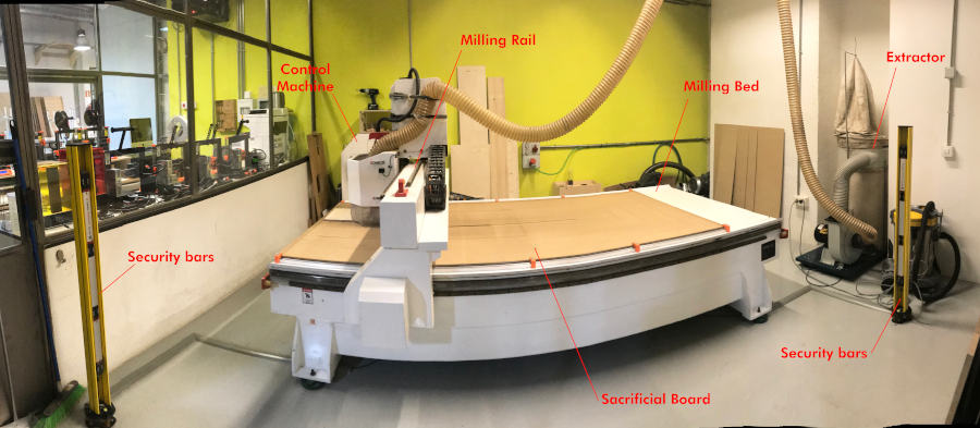
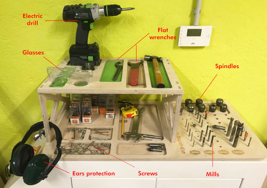
Inside the room, we have a staff where we have the personal protective equipment (glasses and ear protection), the tools to change the milling bits and fix the material to the sacrificial bed, the spindles and the milling bits.
To operate the machine, we have a separate station where we turn the machine on-off and send our files through a USB port. From here, a long cable comes out that connects to a remote control. This control allows us to launch our files at a certain distance from the machine.
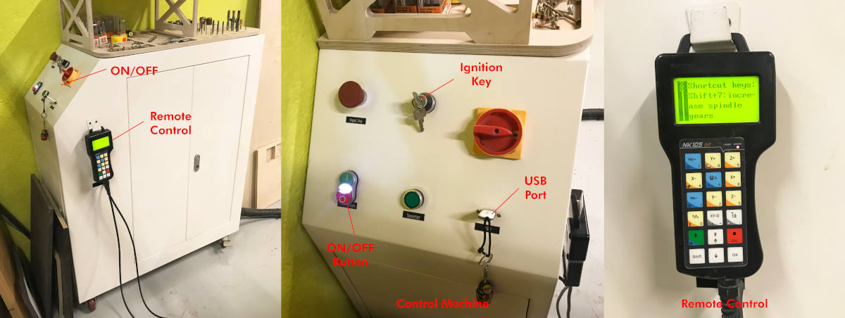
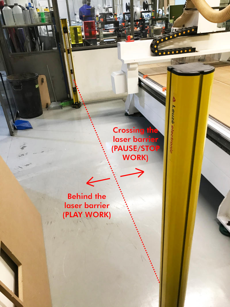
When we have prepared our material and calibrated the machine, we pass the laser barrier with our remote control, and we upload the files from the other side of the barrier. If we see that the milling machine is doing something wrong, we cross the barrier with our foot, and the CNC pauses the work waiting for us to continue with the work, or cancel it.
- TEST RUNOUT, ALIGNMENT, SPEEDS AND FEEDS OF THE MACHINE
-
_CUT2D
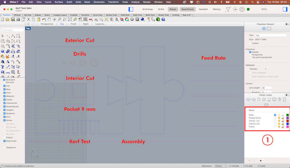
The first thing I am going to do is a small test puzzle on the CNC to learn how to make drills, dogsbones, exterior cuts, interior cuts, assemblies, Kerf test, alignment and a feed rate to check what is the optimal speed for the cutting wood will be as clean as possible.
To do this, in Rhinoceros, I draw each of the parts that I want to test by layers and export it as a Puzzle Kerf Test.STP file.
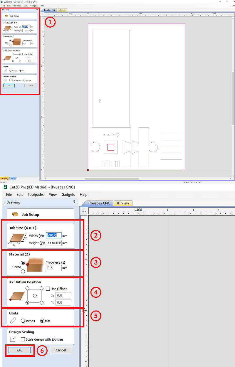
At the fab lab IED Madrid we use Cut2D to prepare the file to be milled. When I export the file, the first thing I have to do is set the Job Size and Thinckness measurements of the board where we are going to mill the puzzle.
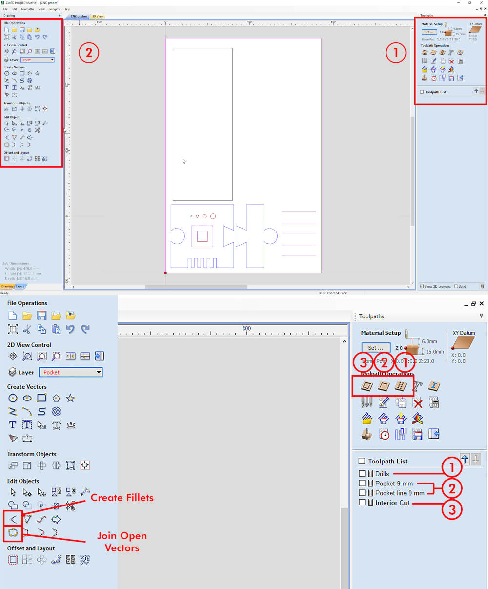
Once this is done, I go layer by layer establishing the necessary parameters to get our piece. The cutting workflow that we always follow is: Drills, Pockets, Interior Cut and Exterior Cut.
So I select our layer (Drills), and on the right a Toolpaths dropdown appears, where the (1) are the features to make Drills, (2) the features to make Pockets, (3) the features to make Cuts. Below, as we establish the types of cuts for each layer, a Toolpath list will appear with the types of cuts that we have established and named.
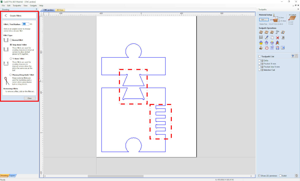
On the left drop-down, there are two very important tools that we must familiarize ourselves with. Create fillets, used to draw in situ the dogbones of the pieces to be cut, and Join Open Vector, used to verify and close any possible object that does not have closed polylines. It is VERY IMPORTANT the objects have closed polylines and there are no double lines on the drawing.
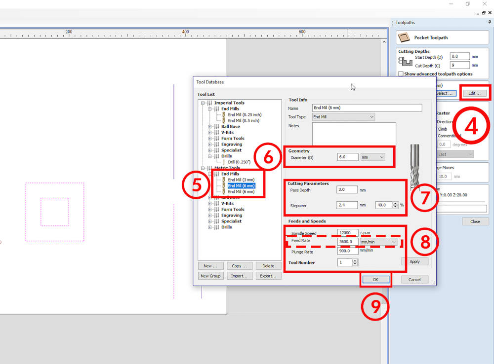
When I select one of the types of cut that I am going to use (pocket, drills or cut), the first thing I have to do is determine the parameters of the end mill. In Tool Database > Edit ..., a new window will appear. On the right, it will indicate a series of end mills that the program has saved by default or we have added.
In our case, I am going to work with a 6 mm end mill. On the right, I have an important sections: the geometry of the mill, the depth and entry step of the end mill, the feeds and speeds.
During Neil's class, we talked about chip load and feed rate. According to theory, to determine the best Feed Rate of a cut, the ideal would be to apply the formula, which is:
Feed rate (mm / min) = Chip load x flute number x r.p.m
However, our crewmate Mauro and other CNC machines experts, determine that the formula is not very reliable 🙃. They all agree that tif we put the feed speed very high, the cleaner cut and the chip load is much larger.
For the fittings and shape definition that I am going to mill, it is important to define the Fillets in the geometry, where the milling bit will pass. In Cut 2D, we can determine the Dog-bones and T-bones from Create Fillets. Or else, we can draw it directly on our parameterized drawing.
Once we have determined all the exterior cuts, we have to place the clamping tabs of the pieces. With the Toolpath Tabs tool I can determine the number of tabs we want to put and at what distance. And in case a tab is located in a bad position, we can move it and place it in a more accessible place.
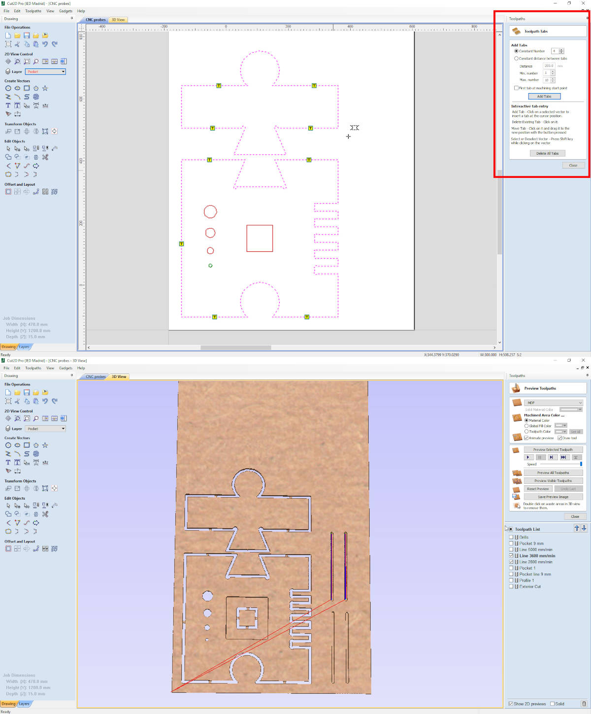
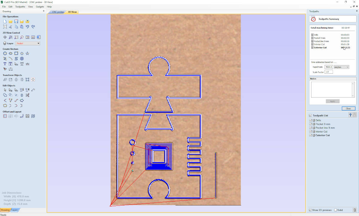
When we have all our modified layers, fillets and tabs drawn, with the simulator I see how the machine would make our cuts and thanks to the program it determines the approximate cutting time that each modified layer would have.
-
_CNC MACHINE
Once I have prepared the file that I am going to cut, we have to prepare the machine, the board and the end mill I am going to use.
The first thing is prepare the material. In the fab lab IED Madrid we do not have a vacuum bed, so we have to fix the material to the sacrifice bed with screws.
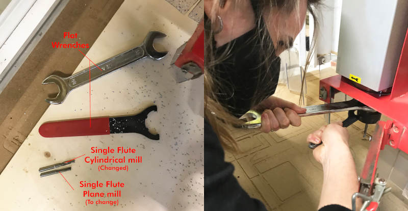
To cut the birch plywood board I am going to use a 6 mm flat milling bit, which we change with two flat wrenches.
Once we have done it, we are going to calibrate 0 in X and Y. As point 0, what we do is to take (approximately) the edge of the board horizontally and vertically as a reference, and we place the milling bit axis with the edges.
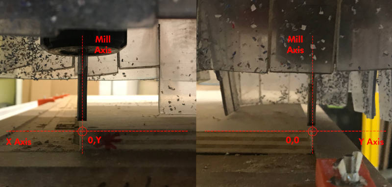
Here you can see a small video where Luis (IED Madrid fab lab technician) and me calibrate the XY axis:
To calibrate Z axis, the first thing we move is the milling bit to the center of the board, and with the metal probe we establish point 0.
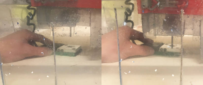
In this short video you can see the workflow we follow to calibrate the Z axis:
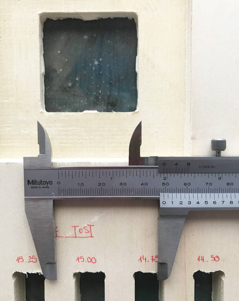
(12/03/2021 19:28 p.m.). This was the end result of the first puzzle on the CNC machine. The cut was pretty good, but nevertheless I set the cut parameters wrong on the lace piece (I set an inside cut instead of an axis cut) and the lace was too loose.
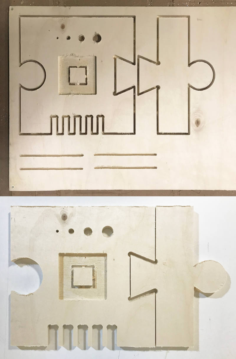
I repeated the cut again, but this time making the exterior cuts of both pieces along the axis of the milling bit. Finally, the pieces fit together correctly! Regarding the Kerf test, I realized that the CNC machines are quite precise in the tolerances.
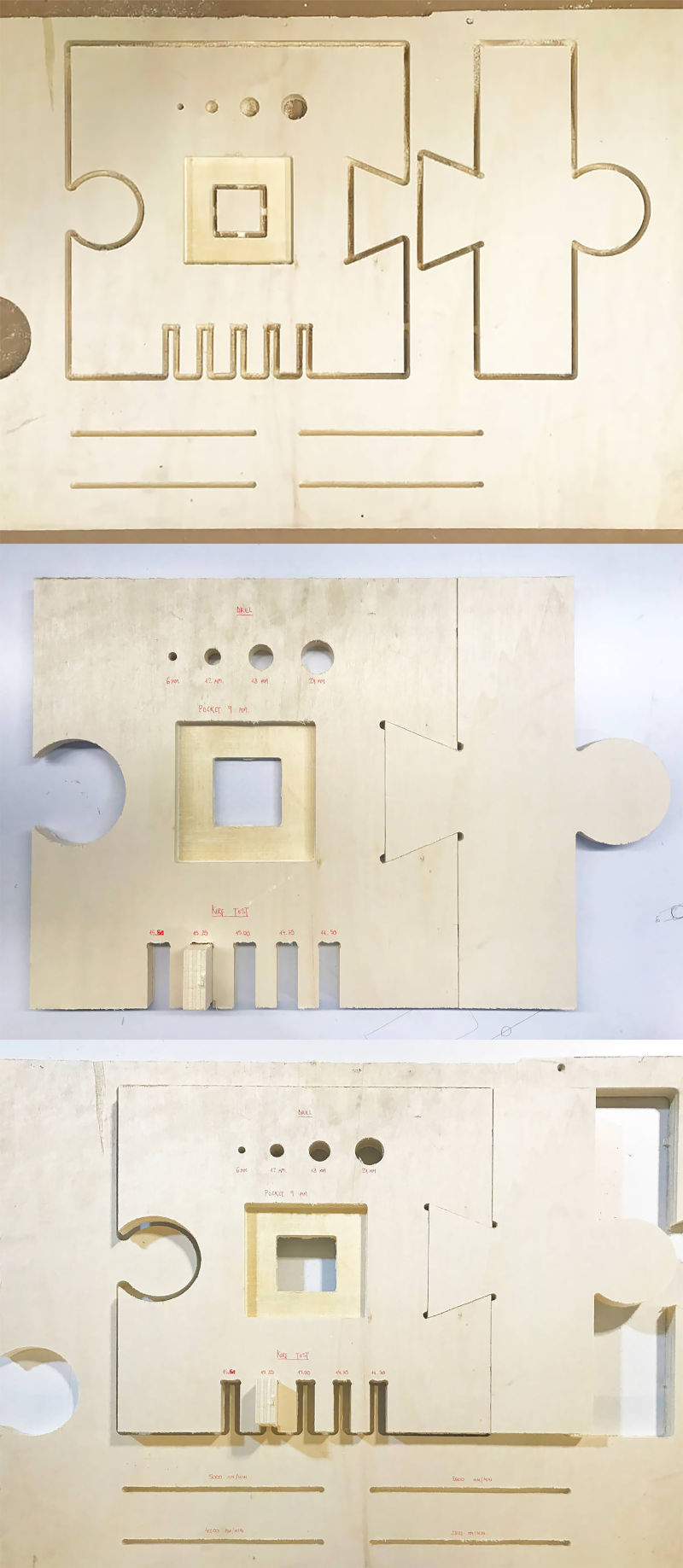
Regarding the interior cut of the square piece, its interior measurement is (more or less) perfect, 50x50 mm (there is a slight variation of 1 mm of approximate tolerance, which helps us to know better how we should make the fittings for the individual assignment.
-
_GROUP MEETING AT FAB LAB UE MADRID AND MAURO´S HOMELAB
(13/03/2021 18:25 p.m.) During the weekend, I had the opportunity to share work, conversation and experiences in person with three of my remote crewmates from Fab Lab Leon: Alberto, Mauro and Mickaël 😍😍😍.
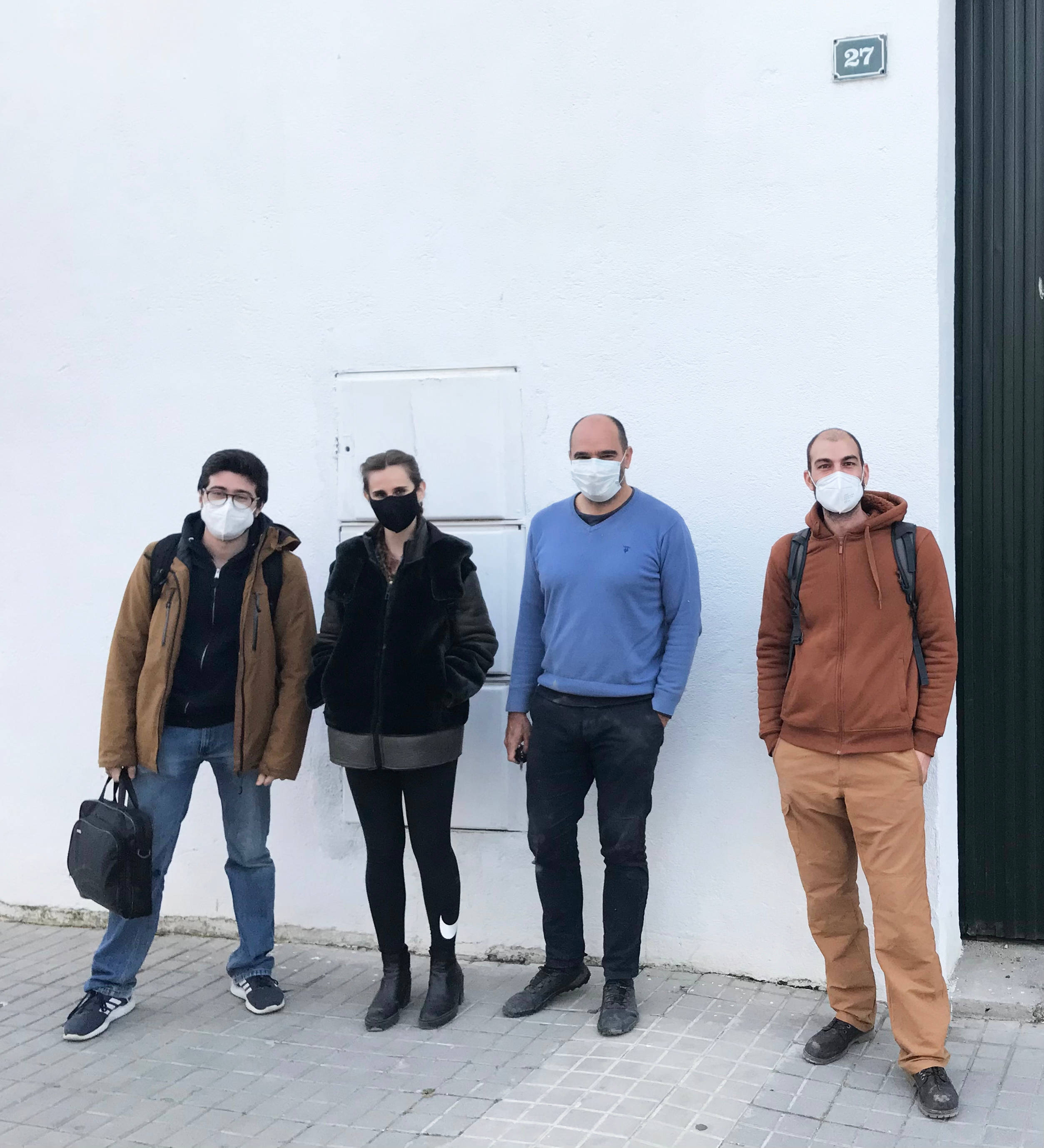
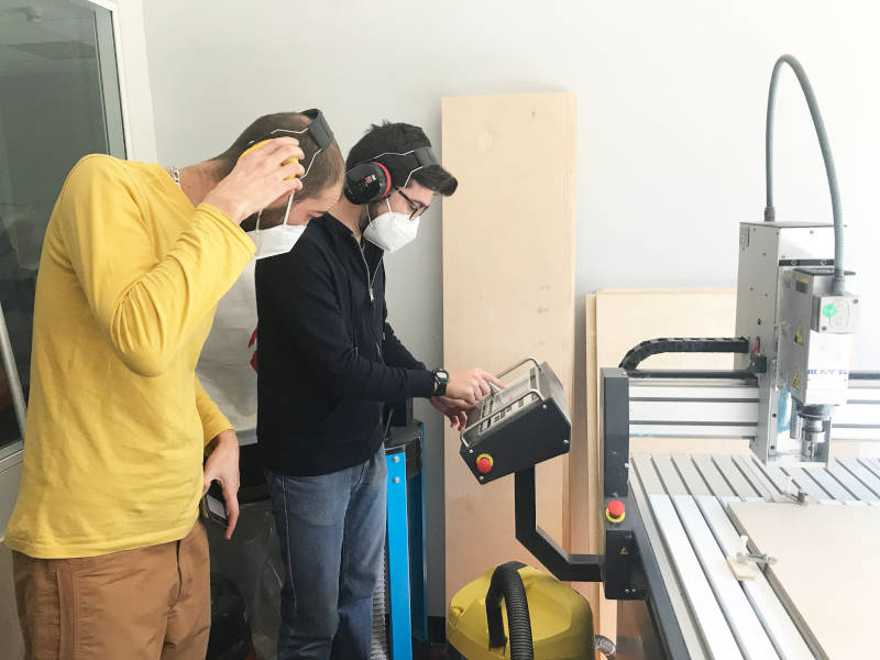
Mickaël has come from Cuenca to Madrid this weekend to work with us on CNC machine week. So, during Saturday and Sunday, as is becoming tradition, Alberto, Mickaël and me were working on our individual and group assignment at the fab lab UE Madrid.
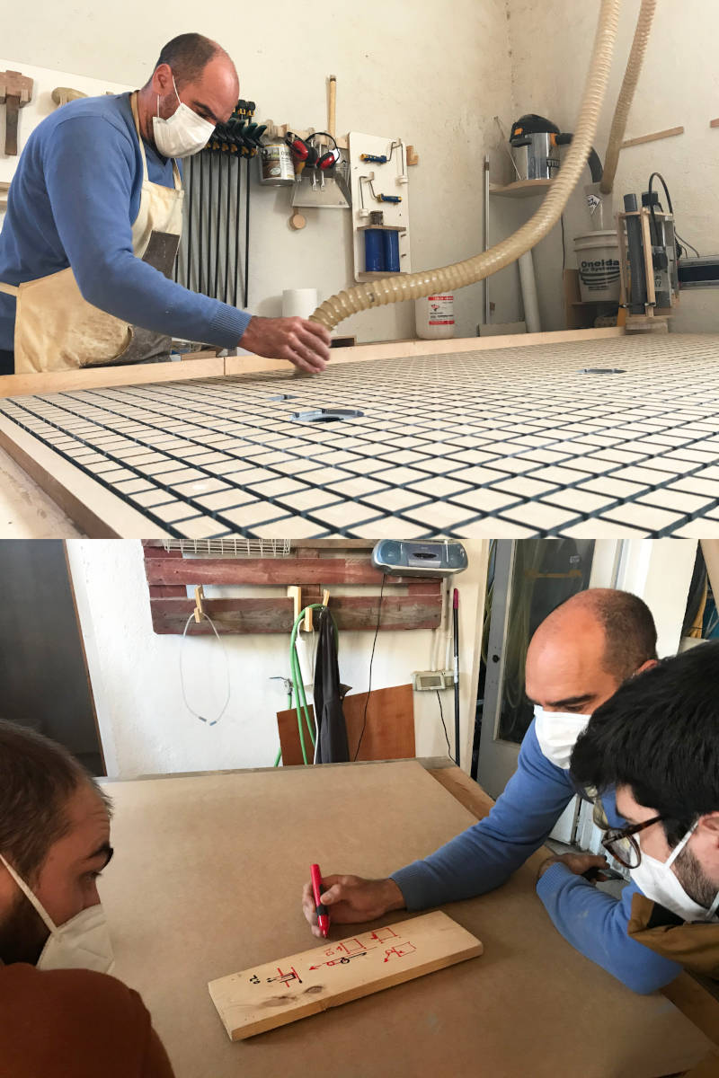
In the afternoon, Mauro invited us to his homelab in Brunete, where he has a huge CNC machine. In it he has manufactured a vacuum bed himself 😍, and he showed us how he installed and calibrated it. In addition, he gave us a great masterclass about how to cut, mill, prepare files and cuts and how to locate dog-bones and t-bones correctly. It was a fantastic day! 💚💚💚
Individual Assignment
FRANKENMANNEQUIN
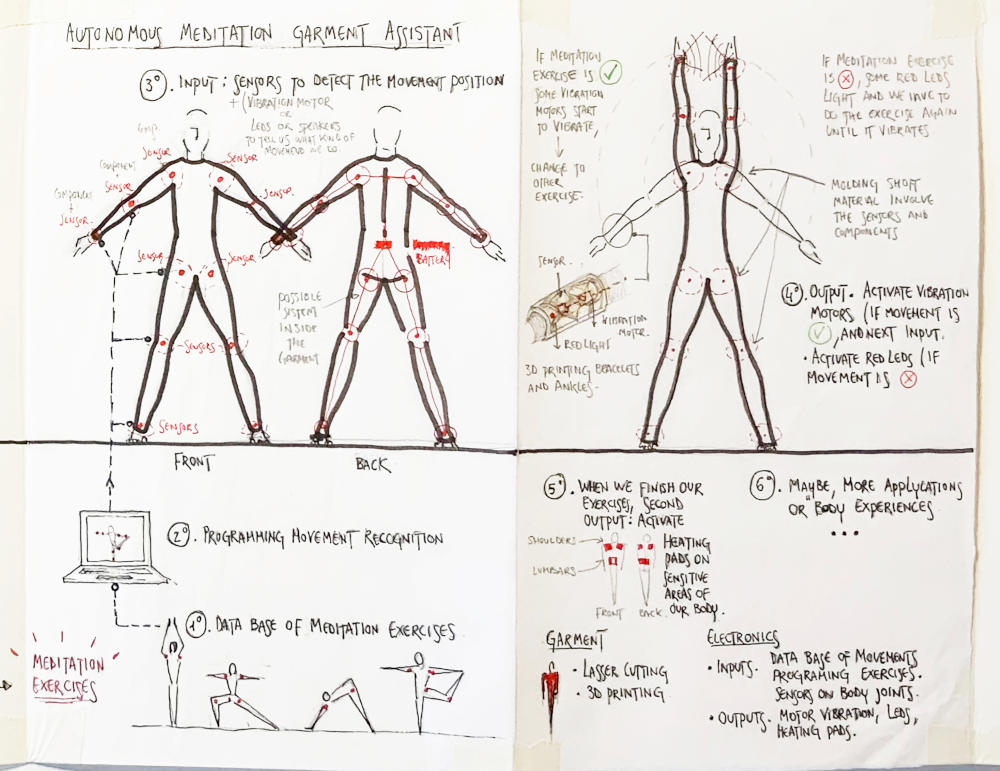
For this assignment, I wanted to focus the object I wanted to design on something that I could use in my final project. As I want to make a wearable adjusted to my body measurements, I have decided to make an auxiliary tool for my project, in this case: a personalized mannequin.
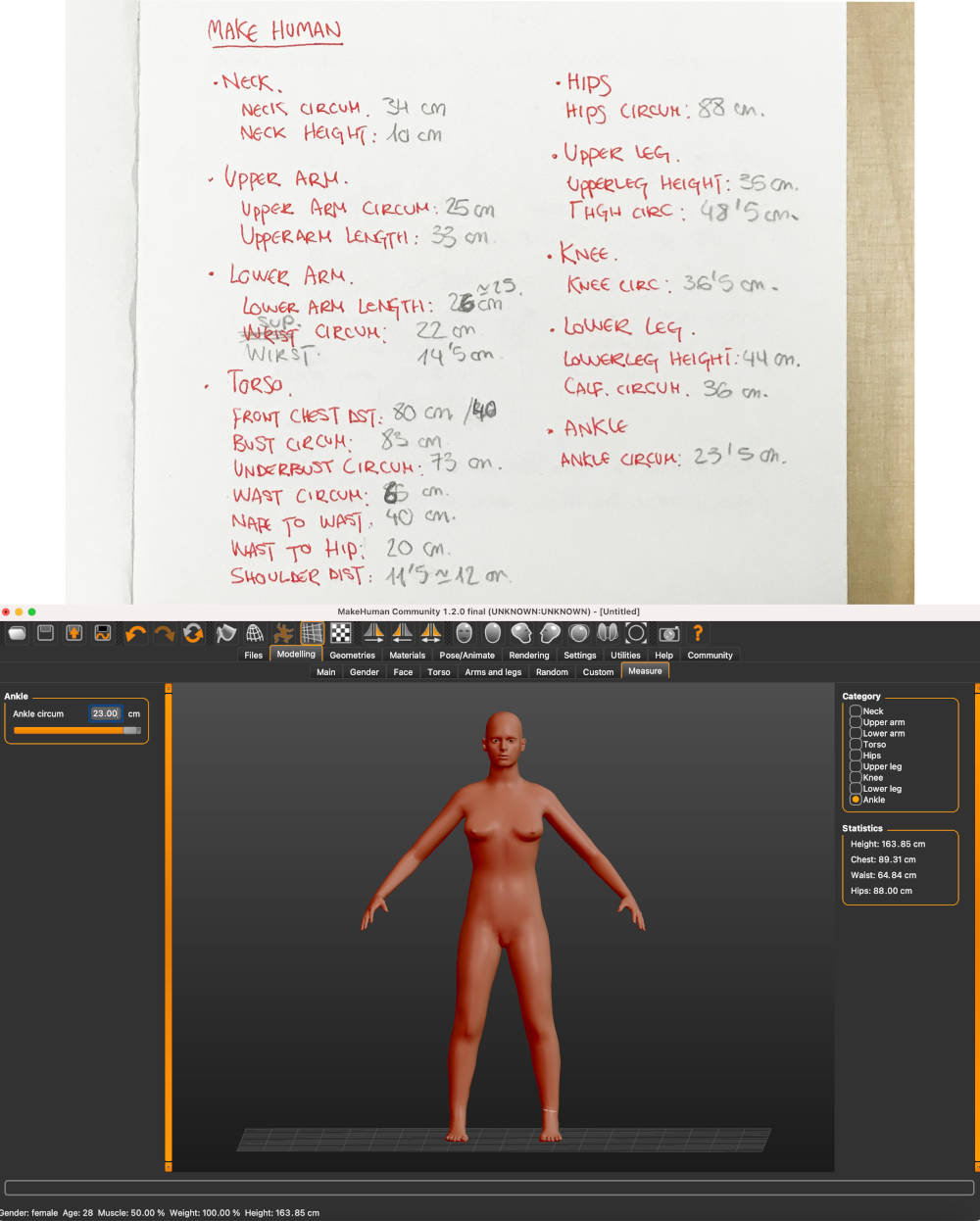
To make my personal mannequin, I have measured all the necessary parts of my body and I have made a new Make Human model (as I did at Week 2). Once our model is created, we export it as .STL. Here you can see the file, Make Human Mannequin.STL
To get started, I opened the Slicer Fusion 360 Software and imported my model's .STL file. At first, when I started to create the slices of my full-body model, I found that if I tried to make the mannequin in one piece, I had certain body parts (such as hands and feet) that seemed very unstable and could break.
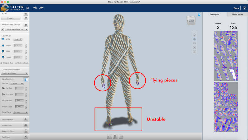
So to be sure and not waste too much material, I decided to make the mannequin by parts. In this case the head does not interest us much for the mannequin, so I divided, in Rhinoceros, the body into: bust, arms and legs.
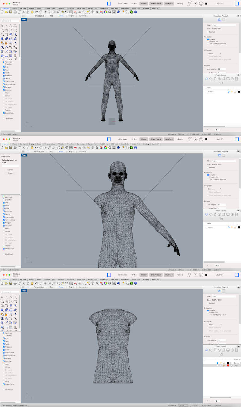
To separate each of the body parts, I drew some plan rectangles that I strategically placed in the areas where I wanted to cut the bust on the front view.
With the TrimMesh command, I select the element to be trimmed and then the element to be removed. To close the bust holes, with the Fill Holes command, we select the open polylines of our mesh and we will close the solid.
Once the bust is obtained, we save the object again in .STL.
Once the bust has been imported to Slicer, one of the first steps that we must check is that our model is in Original Size and in Units mm. To configure the material with we are going to create our slicers, we go to the Pencil tool. In the + symbol, we are going to create and configure the measurements of our board.
(11.03.2021 16:48 p.m) During Thursday, Alberto was in charge of buying the woods that Mickaël, he and I were going to use at the Fab Lab UE Madrid during this weekend. 💚
(11.03.2021 10:52 a.m) Mauro, as a good expert, advised us, at our local review, some companies that worked with good quality woods. In this case, the selection we made was a 15 mm birch plywood.
So with the measurements of the boards purchased, we enter the material data and incorporate about 25 mm of margins and we can configure the Cutting Tool Parameters.
In my experience with the software, the configuration of the Cutting Tool Parameters has not been very useful to me. When I exported some parts, the established Offset was not applied or a measurement that was not the desired was configured. 🤷♀️
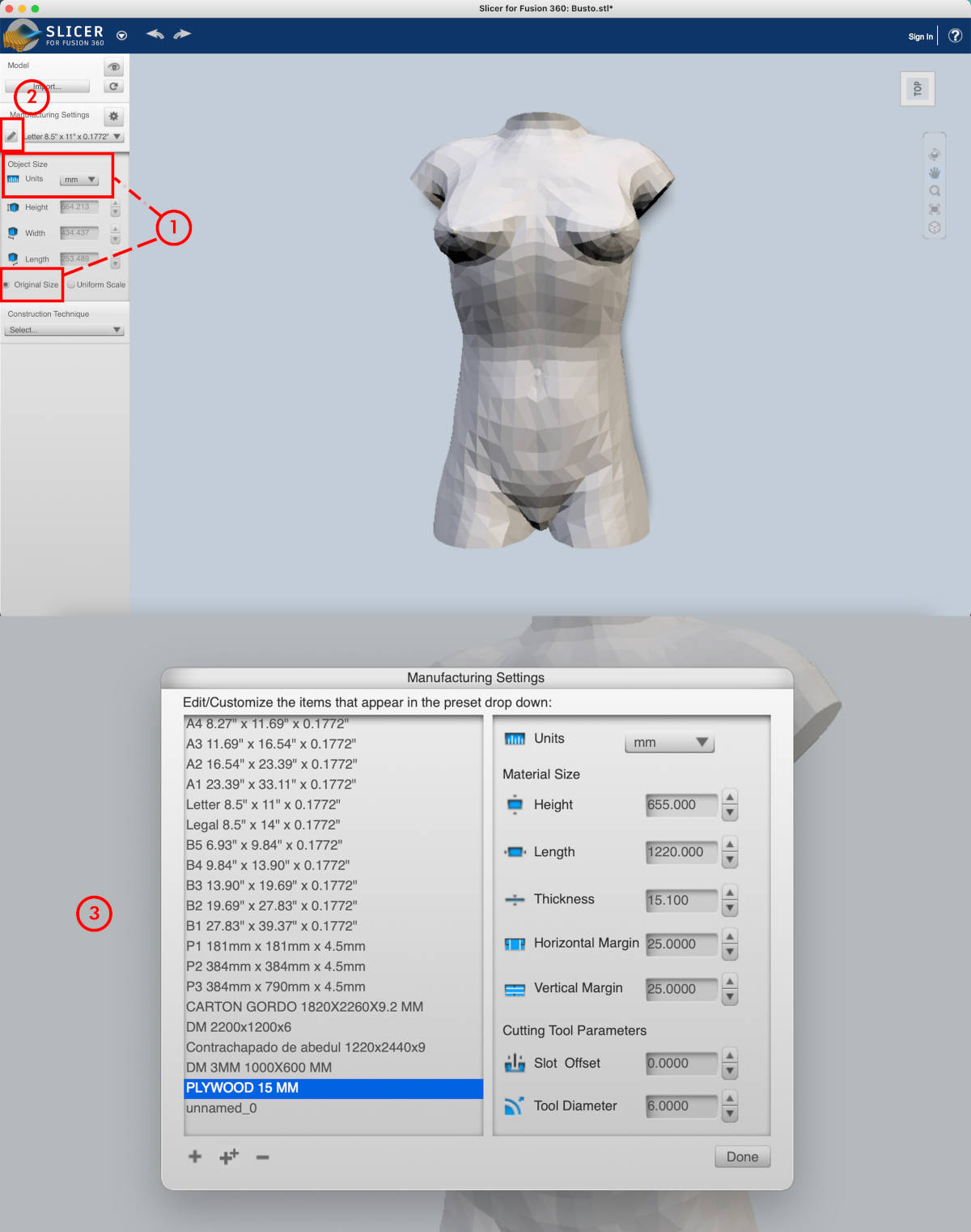
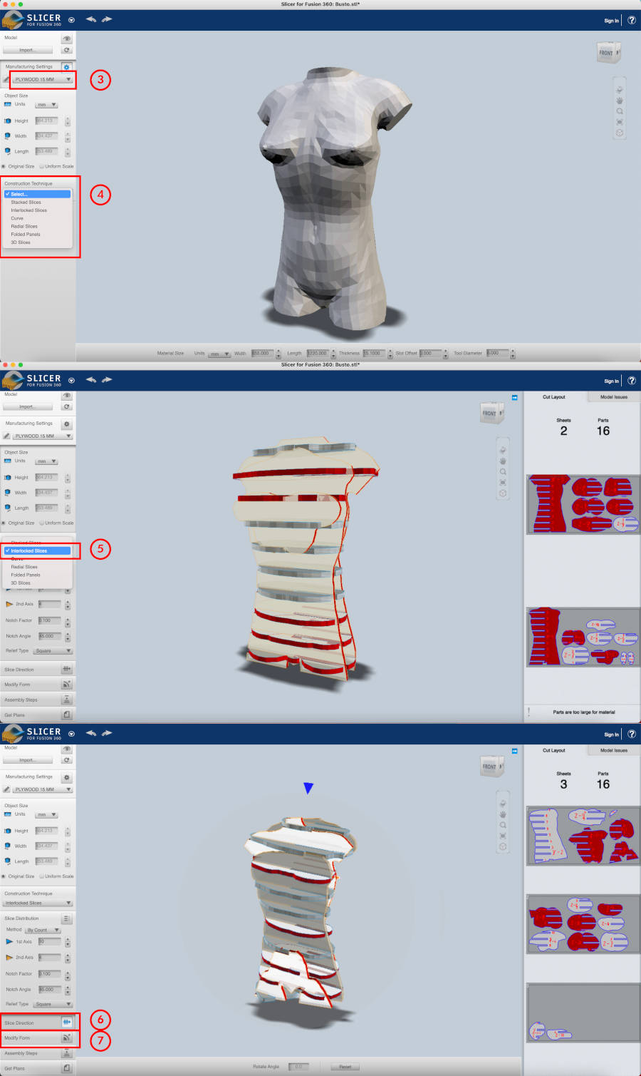
When we have the settings configured, we select our configuration board to use. And then we select what kind of thecnique we want to make our slicers. In my case, I have selected the Interlocked slices option.
When I select the option, suddenly the object becomes to a simulation model made from slices with the thickness of the material that we have predefined.
The pieces in red means there are slicers that, depending on their location or distribution in the model space, may break or are unstable.
On the left, we can adjust and configurate the slices. In the Slice Distribution bar, we can add more or fewer pieces in the model on the XYZ axis. With the Slice Direction tool, we can change the orientation of the pieces to taste and with the Modify Form tool, we can move the slicers one by one to the position of the model where the piece is (supposedly) better adhered among the others.
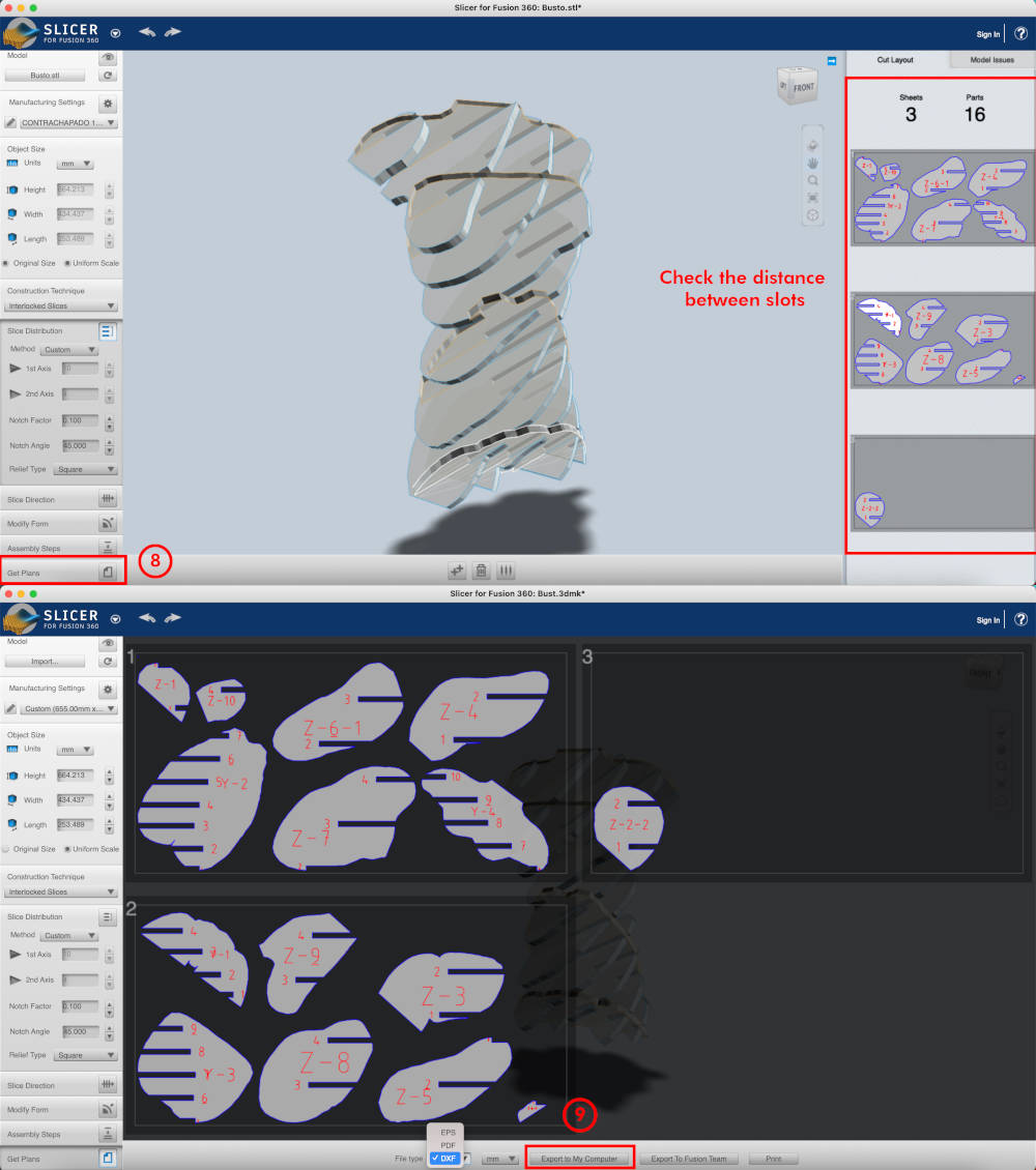
Once the desired shape is defined, we have to verify all the slicers have an optimal separation to configure the dogbones later.
To export the slicers, in Get Plans we select the DXF file and export them to our computer.
We import the file into Rhinoceros, and we are going to see Slicer has imported lines and extruded surfaces on the Z axis. 😅
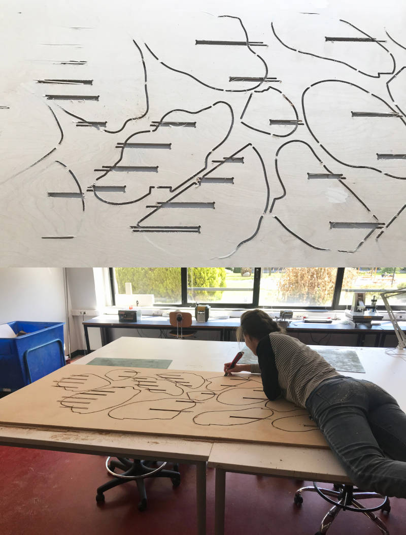
To make closed polylines of the whole set, we draw a rectangle in plan and move it on the Z axis a short distance. On Front view, we write the command Section. We select all the imported slicer surfaces, [ENTER], select from one end to the other the direction of the created rectangle and [ENTER]. Immediately, the program generates a closed polylines of all created surfaces and slicers.
As these polylines have been created at a distance from Z = 0, we select all slicers and move them to the Z = 0 axis for convenience.
(11.03.2021 18:03 p.m) Our crewmate Mauro, during the Saturday, gave us advice for tongue and groove pieces. The idea is to make a closed polyline with the base shape of the piece. And then, make part an open polyline to the slots. In this way, when we order to mill our CNC pieces, it will first make the fitting grooves with right angles, and then the base shapes. With this technique aggressive angle changes in XY plane are avoided and the mill does not lose speed in some areas that could damage the material.
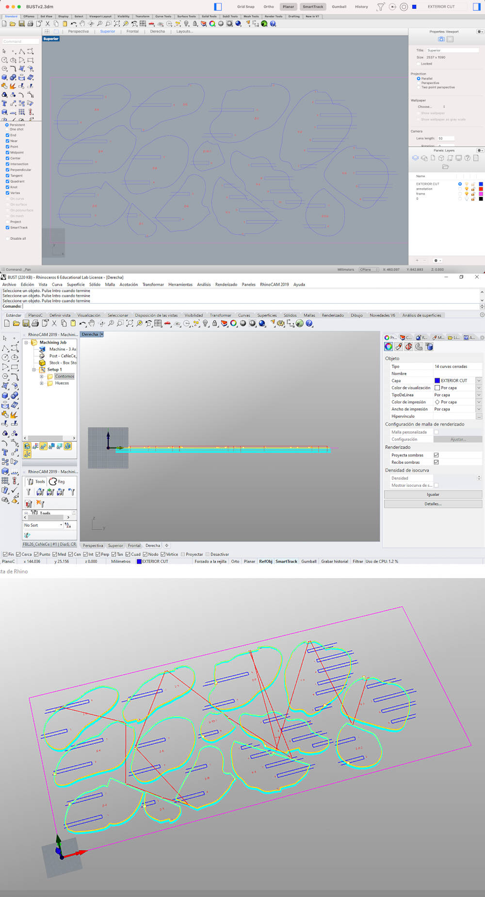
(14.03.2021 11:29 a.m) Once the file is prepared, the Fab Lab UE uses RhinoCAM to launch the files to be milled. So we configure them and prepare the Plywood board on the CNC bed.
(14.03.2021 13:43 p.m) While my pieces were being milled, Alberto stayed watching the machine while I took Mickaël to the Atocha station so he could catch his train back to Cuenca. See you in two weeks!! 🚄💚
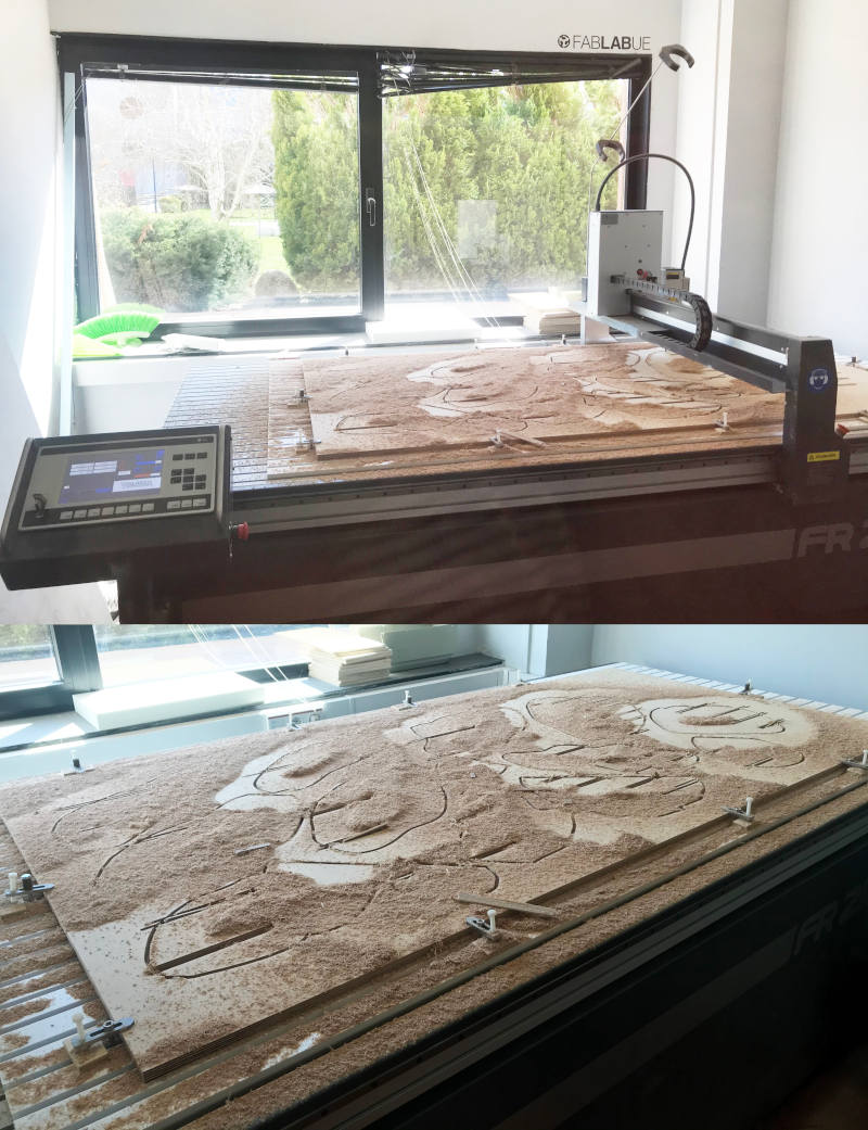
1 hour and 40 minutes later, the pieces were cut! 😍 We vacuum all the chips formed around the board, but we discovered that the machine had not been able to cut the entire perimeter of the pieces. That means that the CNC´s sacrificial table was out of calibration 😅. But luckily the machine just didn't cut a fine thickness of the plywood layer and we could remove easily.
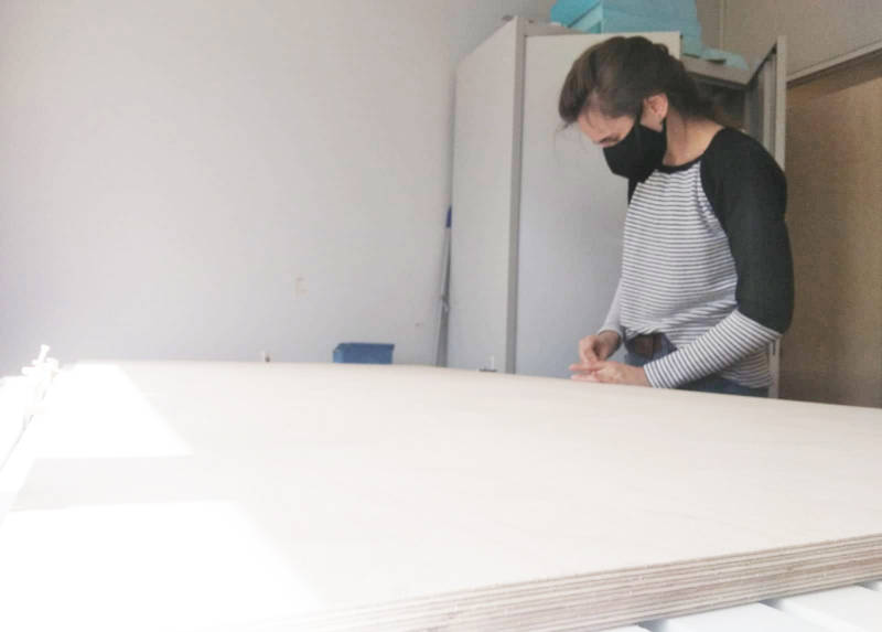
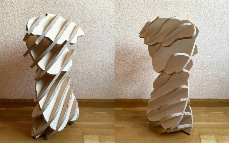
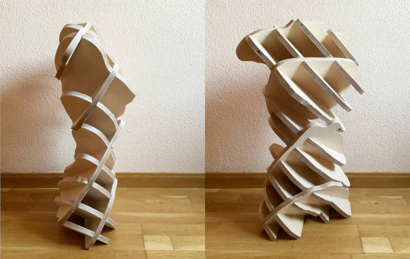
Once at home, I sanded all the slicers well and began to assemble all bust pieces. Here you can see a time-lapse of the assembly process:
And that is the final result!! 😍😍
To make the arm pieces was a bit more complicated. By having smaller measurements, the 15 mm material we had bought did not work for the arm and some pieces on the model are flying 😅 and other are unstable.
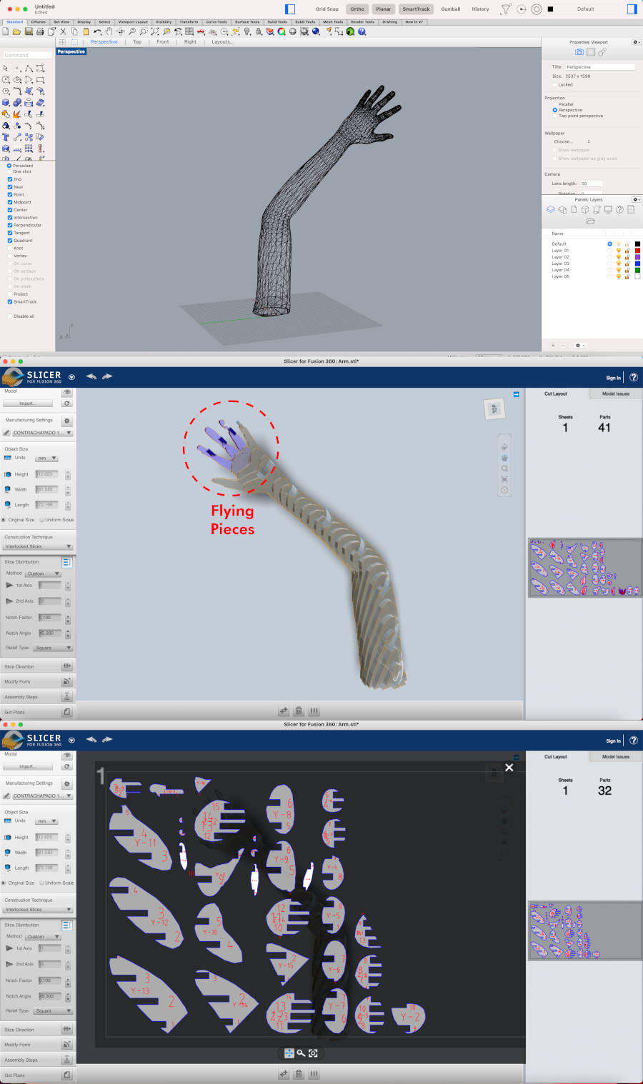
So, to test, I decided to model the arm to cut it on the laser cutting machine.
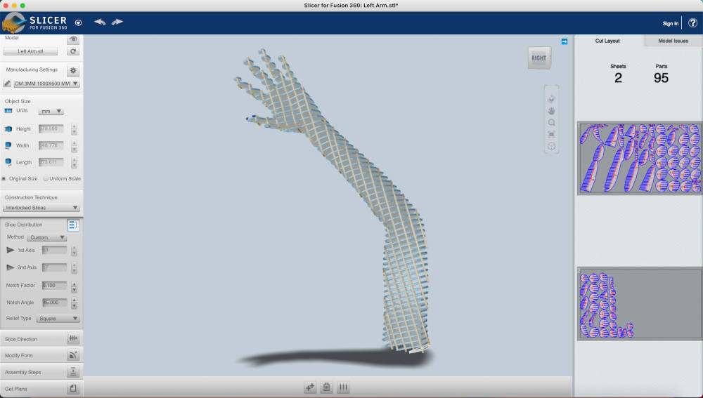
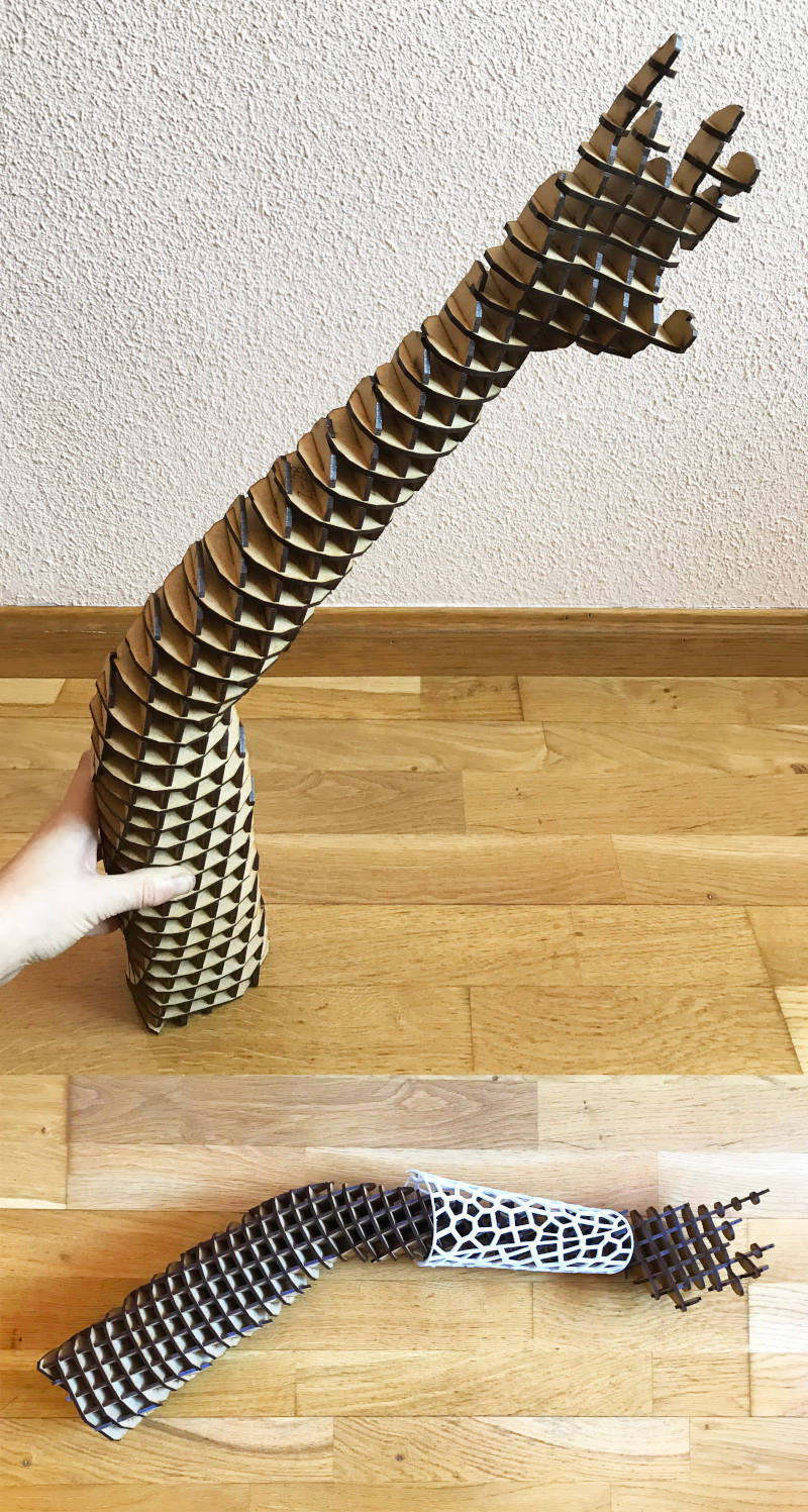
16.03.2021 9:25 a.m. As I did with the bust, I prepared the files, but in this occasion without separating the tongue and groove from the base shape of the pieces. 45 minutes later, I got the pieces cut and assembled. Here you can see the process video:
And this is the final result! To check that the arm measurements are well adjusted, I have taken the brazers that I made in Week 05 with my measurements. And they are well !! 😍
In some of the areas of the fingers, it was little impossible to form their outline. It looks like a heavy metal arm. 🤣🤘🤘
For the legs part, I have tried to mill both legs. Mysteriously, if I configured one of the legs correctly, the other would come out in blue as if it were in the air, and some red pieces appeared that did not convey much confidence. 🤔
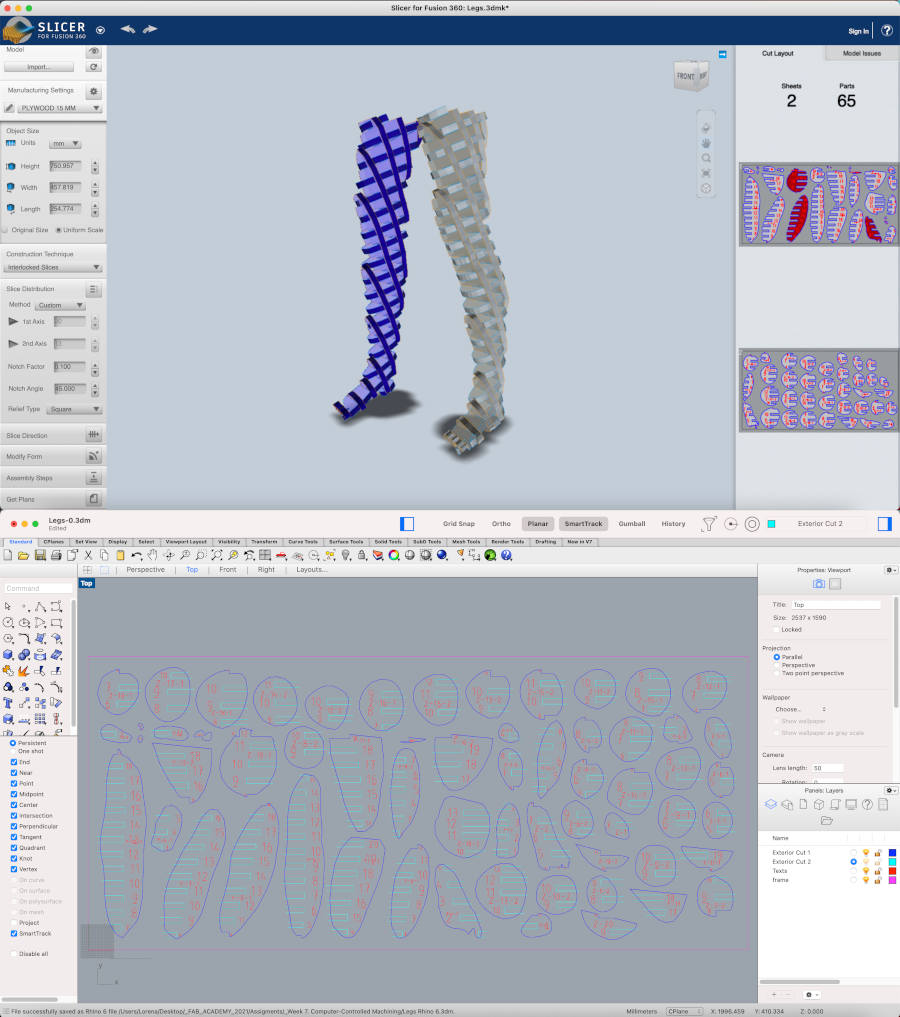
But I decided to try my luck! I prepared the file and Alberto did me the favor to cut the piecesat the fab lab UE Madrid again 💚. The result of cutting these pieces was much better than in the first trial, but I had to sand, one by one, 63 cutted pieces! 😱😱
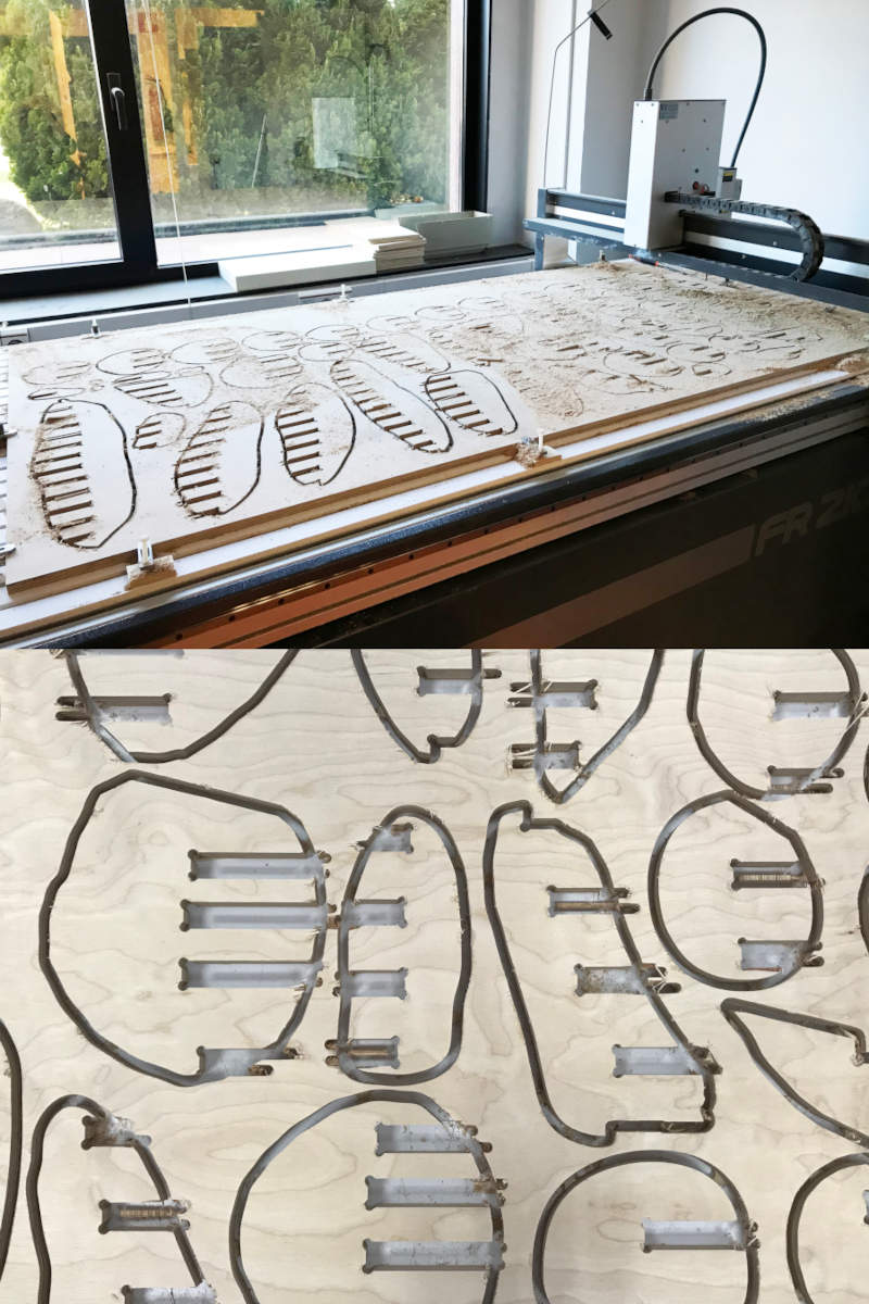
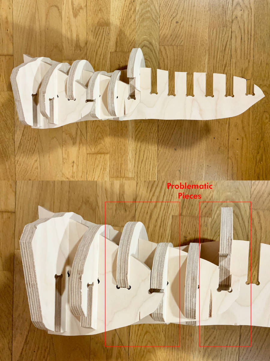
The problem came when he had to asemblying them. 😅Here you can see a time-lapse of the assembly process of the legs:
During the assembly of the upper part of the thigh, several pieces did not fit completely, even having used the same characteristics and techniques as in the bust.😦🤯
I don't know why yet, but I hope to find the solution in the next few days. 💪💪
To finish this assignment, the next spiral would be to try to assemble all the parts of the body and make a suggestion that my instructor, Nuria, told me.
The idea is to finish this Frankenstein by making another part of the body with 3D printing. Since the arm and legs are incomplete, I will try to make one of each in 3D printing in the next few weeks.💪
-
_ASSEMBLYING SUMMARY
- BUST
- Milling time: 1 h 40 minutes (aprox)
- Parts to assemble: 15 Pieces
- ARM
- Lasser Cutting time: 47 minutes (aprox)
- Parts to assemble: 85 Pieces
- LEGS
- Milling time: 3h 20 minutes (aprox)
- Parts to assemble: 63 Pieces
FILES
TEST RUNOUT, ALIGNMENT, SPEEDS AND FEEDS OF THE MACHINE
FRANKENMANNEQUIN