9. Embedded programming
So, Covid-19 hit me right before this cycle started. I tested positive on Tuesday March 15th. At the beginning, I just felt a constant light headache and mild fever shivers, so I kept documenting last week assignment. On Wednesday, I could atted class, although my attention was deffinetly not sharp. And then came the rolldown. Higher fever during over 10 days that finally got my bones, on Friday March 26, into the hospital with a quite strong pneumonia. After a rough weekend, I have started recovering, although still at the Hospital. By no means I want to force things getting everything back up to date, but if I keep feeling like doing so, I will slowly move with my Fab Academy.
For the machine building cycle, we have not been able to meet personally as a group, not only because of my illness, but due to restrictions and lockdowns. Nevertheless, my fellow partners have managed to put up a first spiral of an amazing maze machine, in which I hope to contribute asap.
On Saturday March 20th, I managed to program just the LED on my board. Honestly, I do not remember much of the proccess, it was like my brain was running in just a backend mode... So I have asked permission to have both my computer, boards and a small set of test equipment to go over it again, given I feel well enough for the task.
PWM - pulse widht modulation arduino tutorial
Group assignment: compare the performance and development workflows for different microcontroller families
As a remote student, I am doing the "group" assignments on my own... This one was specially tough for me, since I knew nothing about electronics before I joined Fab Academy. So I am writing this section at the end of the cycle.
I read this article about the SAMD21, where I found this comparison table:
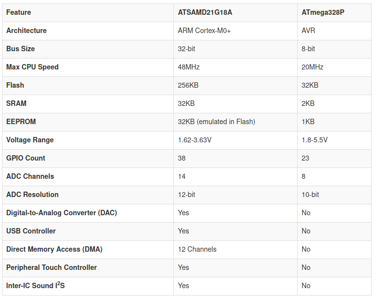
The architecture of the SAMD21 is ARM Cortex-M0+, instead of the AVR architecture of the AT family. The bus size is 32-bit, instead of the 8-bit. The internal clock runs up to 48MHZ, which is more than double the 20Mhz of the chips we are usually using. Also, it runs at 3.3 volts, instead of 5.5.
Besides that, it comes with even more bells and whistles, such an DAC, USB controller, DMA, peripheral touch controller and Inter-IC Sound I2S.
Another great feature is that it has up to 256KB of flash memory. I am mostly using the 1614, which has 16KB, so the difference here is gigantic.
It also features six configurable serial interfaces: they can be used as UART, I2C or SPI.
The USB controller can be used either as device or host. In device mode, it configures itself as a communication device class, so you can connect to it as if it was a serial port.
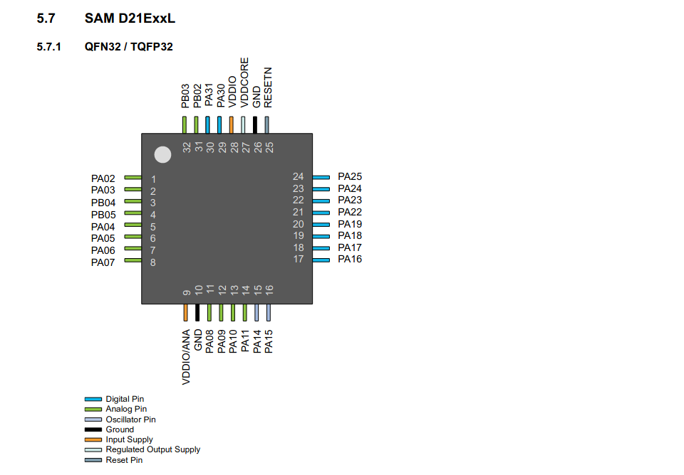
Something I noticed looking at the pinout is that there is up to PA31 in port A, I guess that's one of the perks of being a 32-bit microcontroller. I also noticed, that even the smallest have up to 14 analog pins, capable of doing PWM.
Programming boards using UPDI
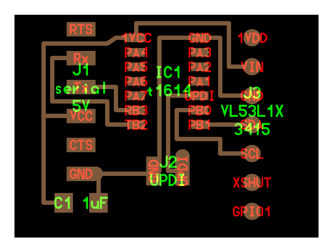
I finally got to program a board using UPDI during the network and communications week. I made a version of Neil's hello VL53L1X, adding an LED and a communications 2x2 header
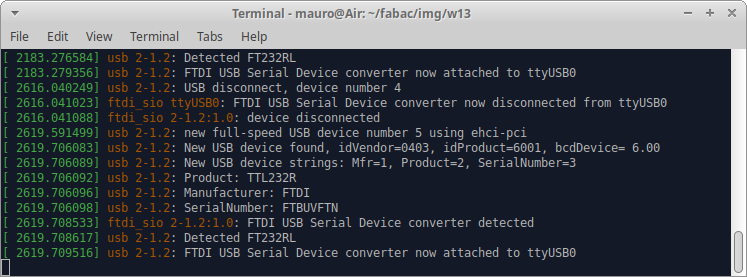
I followed Adrian's docs, installing first pyupdi, by typing pip3 install https://github.com/mraardvark/pyupdi/archive/master.zip in the terminal. Then I ran pip3 install intelhex pylint pyserial, but thwy were already installed. Then, I connected the USB- FTDI cable, and run dmesg-w, to get the port name, which in my case was /dev/ttyUSB0. I connected and disconnected it to make sure I was getting the name right:
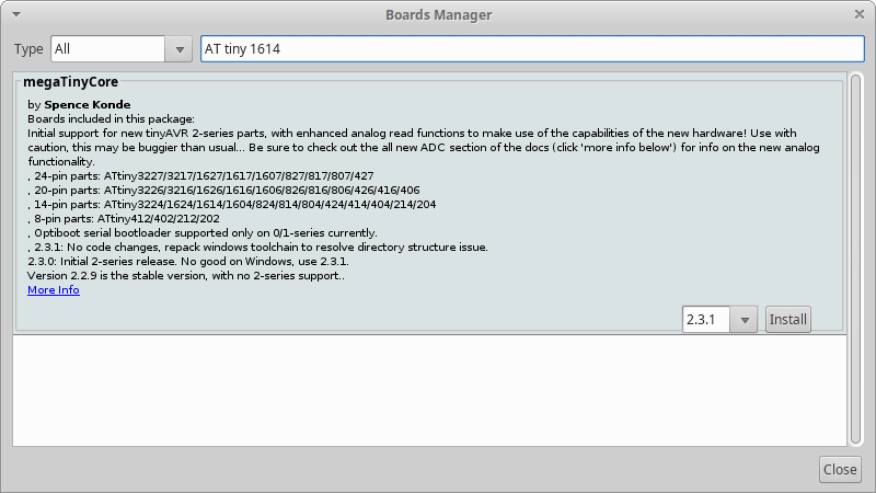
Then, I installed, using the boards manager within the Arduino IDE, the megaTinyCore package, by Spence Konde:
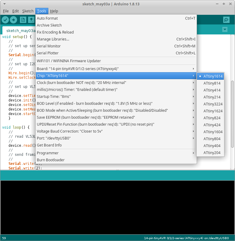
Next, I chose the right board and microcontroller, configured the clock to 20MHz, and the port:
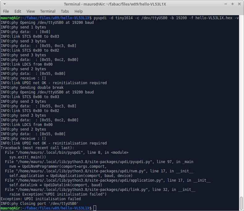
Then, I exported the binary, renamed it to hello-VL53L1X.hex, and, from the project directory ran pyupdi -d tiny1614 -c/dev/ttyUSB0 -b 19200 -f hello-VL53L1X.hex -v. Unfortunanetly, I got an error: UPDI initialisation failed, so I started debugging.
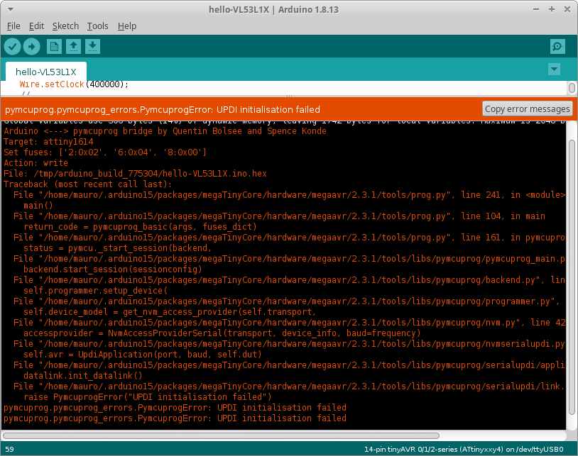
First, I checked all conections. Then, I tested continuity. Then, reflowed the solder, both in the 1614, the UPDI pins and the FTDI-UPDI adapter. But I still had the same problem, so I tried using the Arduino IDE instead of pyupdi from bash: the problem persisted:
Then I checked with my instructor Adrian, who told me that probably I had burnt the microcontroller, so he suggested to desolder it and place a new one. But after replacing it, I am still having the same problem...
Finally everything is working
It turns out that I was having trouble with my FTDI cable. I got two FTDI to USB convertors from Amazon, and from there on, I have been able to program every board I have been making, no matter if I was using UPDI or ISP.
One of the very first I succesfully uploaded was the blink program for the board I made during week 7. Then I wrote a little program that turned on the LED when the button was pressed.
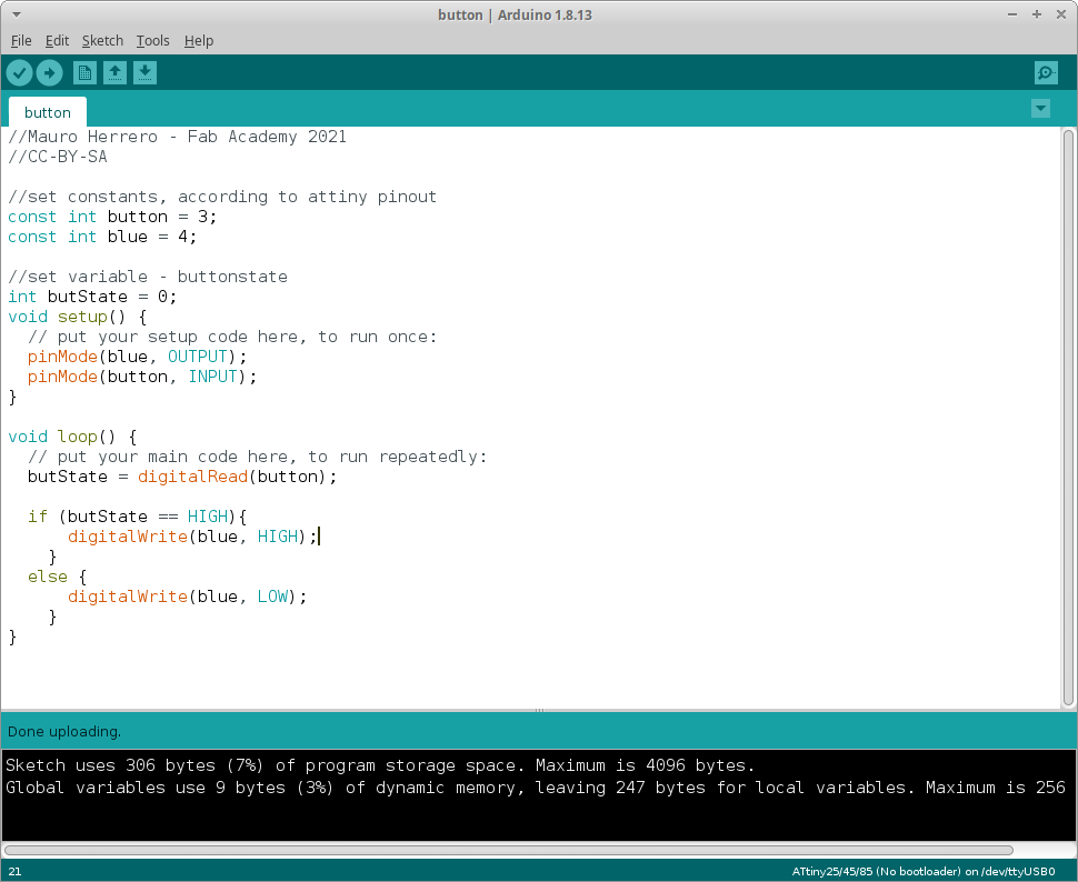
And finally I found a program, by David A. Mellis, which used the button as a switch. The original code was for Arduino, so I modified the pins, and change variable names to fit my needs.
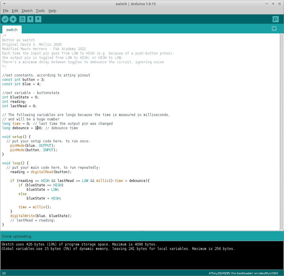
And this program is finally working on my board:
The files of the three programs can be found here:
Reading a microcontroller datasheet
In all honesty, during this week I did tried to read a datasheet... and understood next to nothing. But over the rest of the cycle I have had to go several times to different datasheets, including the t44, t45, the H-bridge A4953 and most often, while developing and debugging my final project, the t1614.
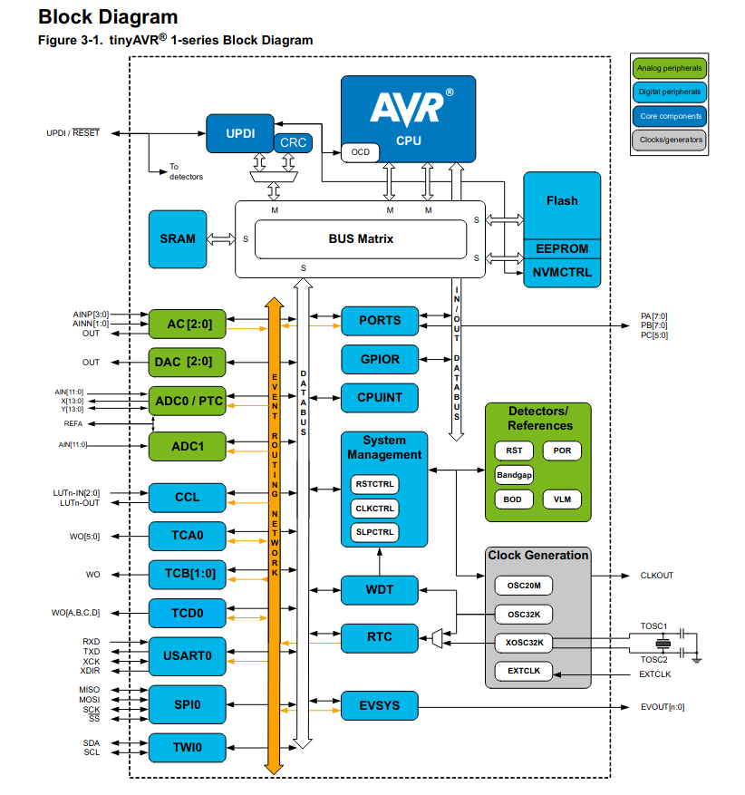
From the block diagram, I understood that there are specific pins for specific tasks, such as UPDI for programming, SDA & SCL for connecting to I2C, Rx&Tx for serial communication, analog and digital peripherals...
Not only in the datasheet I found unvaluable information, also in Spence Konde GitHub page. I even drew my version of his pinout scheme, using Inkscape:

I also read about the port input/output configuration, and learnt that all PORT pins are asynchronous event system generators. Each port must be configured as input or output. Each pin has a number, which correlates to the corresponding bit (PA0 -> Port A; bit 0). If the direction bit is set to 0, the pin is configured as input, wheras if it is set to 1, it will be an output pin.
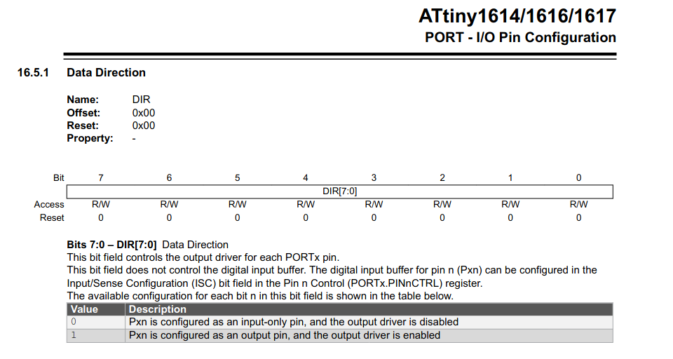
If the pin is configured as input-only, there is another registry, PINnCTRL, in which, with the value of bit 3 PULLUPEN, the internal pull-up resistor can be enabled.
In order to configure the output pins to be driven high, the register used is OUT. If a read-modify-write operation is to be performed, then OUTSET should be used. OUTTGL toogles the value of the corresponding pin: 1 toogles, 0 has no effect; this is also a non read-modify-write operation.
Bitwise operations is something I want to get my hands into. For my final project, I wrote a piece of code to do sofware produced PWM, to operate the stepper with two H-bridges. But I used Arduino's digitalWrite(), which is a rather slow operation for two reasons: first it performs checks before actually writing, and second, it accesses only one pin at the time. Using bitwise operations more than just one pin can be accessed at the same time, saving CPU cycles. I found a great explanation by James in his Bald Engineer blog.