16. Applications and implications
The end is near... So now it is time to recap, gather what we have leart in the past weeks, and with a final push, put together a final project. The main requisite is that is has to be a masterpice, impliying that with it we demostrate we own enough skills to make almost anything.
Final project proposal: fab-o-meter
At the begining of the 2021 Fab Academy cycle, I wanted to make a device that measures irregular walls from a given distance, so for instance, counters or shelves could be cut to the precise shape and dimension so it actually fits.
After 15 weeks of Fab Academy, I now have a much clearer vision of what can I accomplish in this very first spiral of development, given my skills and available time. The device will basically do what I expected at first, but is the output in what I will have to work more in the next spirals.
What will it do?
The device will make a linear move along a rail in the side of a test bench, while taking measurements with a distance sensor to the irregular "wall" in front of it. Ideally, with the data gathered, an irregular shape that fits that wall can be cut using a CNC mill.
Who's done what beforehand?
The commertial application that might resemble more what I am making is this Leica Disto s-910, combined with the sofware from Cabinet Vision. It is a quite high-end solution, aimed to medium or large contractors, with a price completely out of reach of a hobbyist.
Ivan Sanchez, from Fab Lab Oulu, made in the 2017 cycle thisModular multimeter, integrating also a distance sensor. He wanted to setup an I2C network for the different modules to comunicate, but in the end did not make it work that way.
I also found an attempt to make a Mini Total Station, by Manu Mohan in 2019, in Fab Lab Trivandrum. He used a laser range finder module, since he wanted to measure longer distances, instad of the VL53L1X from the Fab Lab Inventory.
Jens Dyvik, from Fab Lab Fellesverkstedet, has developed several machines, with very interesting axis modules. I will definetly use one of his fabricatable axis modules for the linear motion system in my final project.
What will you desing
- A test bench, with place for a guide system and a wall, that can be detached.
- A carriage, with a stepper motor and room for batteries and electronics.
- Circuit board, with a button, LED, bipolar stepper driver and the ToF VL53L1X distance sensor.
- Enclousure for the device.
- An interface to output the data sent by the sensor.
What materials and components will be used? Where will they come from?
The test bench is made of 12 mm birch plywood, supplied by Riga Wood.
In the first spiral, the carriage and enclousure will be 3d printed, using regular PLA for the first and Timberfill from Fillamentum.
All electronic components are in the Fab Lab Inventory. Most of them are sourced by Digikey. But the following were sourced via Aliexpress or Amazon Spain by different vendors:
- Allegro A4953 stepper driver
- VL53L1X time of flight sensor
- L53B 5V 1A voltage regulator
- 4 pin SMD micro button
- Colour LEDs
- Nema 14 bipolar stepper
A more detailed list of the materials used and its quantities can be found in the BOM.
Bill of materials
| Item | vendor | quantity | unit price | total |
|---|---|---|---|---|
| 2440x1220x12 birch plywood | Riga Wood | 0.5 | 44.10 | 22.05 |
| Nema 14 0.8A bipolar stepper | StepperOnline | 1 | 9.02 | 9.02 |
| AT Tiny 1614 | Digikey | 1.00 | 0.81 | 0.81 |
| A4953 full-bridge driver | Aliexpress | 2.00 | 0.62 | 1.24 |
| VL53L1X ToF sensor | Aliexpress | 1.00 | 5.37 | 5.37 |
| L53B 5V 1A voltage regulator | Aliexpress | 1.00 | 0.17 | 0.17 |
| Colour LED | Aliexpress | 1.00 | 0.02 | 0.02 |
| 4.99k resistor | Digikey | 2.00 | 0.02 | 0.04 |
| 10k resistor | Digikey | 1.00 | 0.02 | 0.02 |
| 1uF capacitor | Digikey | 3.00 | 0.02 | 0.06 |
| 10uF capacitor | Digikey | 2.00 | 0.02 | 0.04 |
| PCB FR1 7x10cm | Amazon | 1.00 | 0.91 | 0.91 |
| SMD button 4x4x1.5mm | Aliexpress | 1.00 | 0.06 | 0.06 |
| SMD 6 pin 2.54 mm female | Aliexpress | 1.00 | 0.48 | 0.48 |
| SMD 6 pin 2.54 mm male | Aliexpress | 1.00 | 0.07 | 0.07 |
| SMD 3 pin 2.54 male | Aliexpress | 1.00 | 0.05 | 0.05 |
| SMD 2x2 2.54 male header | Aliexpress | 2.00 | 0.05 | 0.10 |
| 9v battery connector | Amazon | 1.00 | 0.27 | 0.27 |
| 9V battery | Amazon | 1.00 | 3.49 | 3.49 |
| DIN 912 M3x12 bolt | Amazon | 4.00 | 0.03 | 0.12 |
| DIN 912 M3x35 bolt | Amazon | 4.00 | 0.09 | 0.36 |
| PLA outlet spoolchange | 3dfils | 65.70 | 0.01 | 0.87 |
| Timberfill for outer case | Timberfill | 140.50 | 0.04 | 6.18 |
| Insert nut M6x12mm | VerduOnline | 6.00 | 0.05 | 0.28 |
| DIN 7991 M6x30 bolt | VerduOnline | 6.00 | 0.07 | 0.41 |
| Total: | 52.49 |
All quantities expressed in metric units & €
What parts and systems will be made
All parts in bold are made using Fab Lab facilities.
The test bench is made with plywood, using the CNC router; it has a flat surface with insert nuts so both rail and test "wall" are detachable, running along its long sides.
The base carriage has been 3d printed in PLA. Along it, there are also separators, to position the stepper at the right height, and the pinion that makes the device move along the rack in the rail.
The electronics board has been milled with the CNC router (yes, the large format Shopbot like, is the one I have easy access to...), and all components will be soldered by hand.
The enclousure of the device will be 3d printed, using both PLA and Timberfill.
The embedded code will be programmed in C, using some external libraries, such as Pololu's VL53L1X and Software Serial. I will use snippets of code by Prof. Gershenfeld to drive the stepper. I will program the routine to make a measure every given displacement of the device.
The interface will be programmed using Processing.
What processes will be used
The list of processes and tools used is the following:
- Project management; tool used: Taskjuggler.
- 2D design, for some parts of the PCB; tool used: Inkscape.
- 3D design, for test bench, carriage & enclousure; tools used: FreeCad & Rhino.
- Electronics desing, for the board; tool used:Kicad
- CNC path planning; tools used: mods for PCB and Vectric Cut2D for woodwork.
- CNC machining, for test bench, rack and PCB board; tools used Shopbot like CNC machine.
- 3d printing path planning; tool used: Prusa Slic3r.
- 3d printing, for pinion, base carriage & enclousure; tool used: FFF 3d printer
- PCB production; tool used: soldering iron.
- PCB debugging; tools used: multimeter, osciloscope & logic analyzer.
- Embedded programming, tools used: Arduino IDE & avrdude.
- Interface programming, tool used: Processing.
- Documenting; tools used: html, css, git andgitlab.
- For just about everithing; tool used: vim.
What questions need to be answered
There are quite a few questions that need to be answered, mostly regarded, but not limited, to the electronics and programming functioning of the device:
- Do the Allegro A4953 full-brige motor driver need PWM pins from the AT Tiny 1614?
- In the AT Tiny 1614, how can PA1 & PA2 be used as SDA & SCL for I2C communication?
- When using Neil's code for the bipolar stepper, how have PWM on/off time, PWM_count & step_count have to be defined, so the stepper makes just one turn?
- For the eletronics board, do I need a 5.0V 1A regulator, or is enough with a 100 mA one? How could one know beforehand?
- In the base carriage, will the nema 14 stepper be powerfull enough to drive the device by sliding instead of using wheels?
- Will the 16k of memory of the AT Tiny 1614 be enough for code + libraries?
- Will I be able to design, make, program, debug and document in time???
I am well aware that I should be able to answer all this questions confidently before procceding. For now, my guess is that with the decissions I have made so far, the device will work... but soon enough will we find out!
How will it be evaluated?
Considering that it is a prototype, it will be successful if:
- Upon the pressing of the button, the stepper starts to turn.
- The embedded program makes a measurement at given points along the movement.
- The device can comunicate via serial with a computer.
- The data recieved in the computer can be visualized and is human readable.
- With a second push of the button, the device comes to stop.
- The documenting is complete.
Project management: Taskjuggler
In the very firs week of the Fab Academy, Neil mentioned Taskjuggler, a tool for project planning and tracking. I stumbled upon it a few times in the past, but never before took the time to getup and running with it. This time, I spent a few hours with it, and I really enjoyed it.
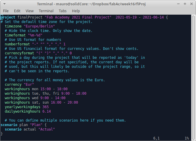
First, I edited my .vimrc file, to enable syntax highlight for it. Then, I went through the manual, specially the tutorial. After that, I started editing my own project, stablishing time frame, working hours and "plan & actual" scenarios.
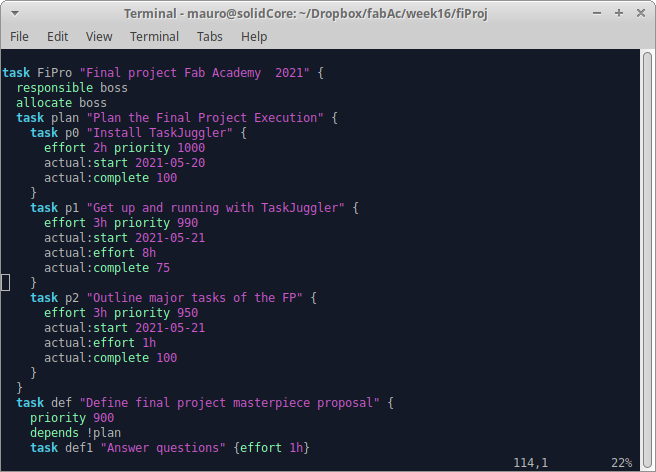
Next, I created the tasks, each one with several sub-tasks, learning functions such as allocate, effort, priority, start, depends and complete.
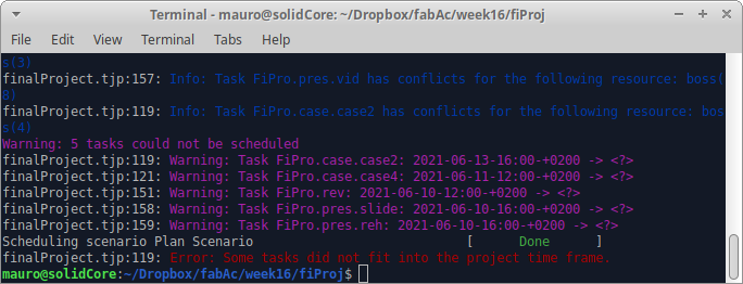
After all tasks were introduced, it was time to actually run the program, just to get a nasty notification: Some tasks did not fit in the project time frame. Bach to re-assign efforts and expanding working hours...
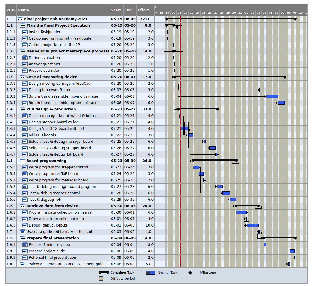
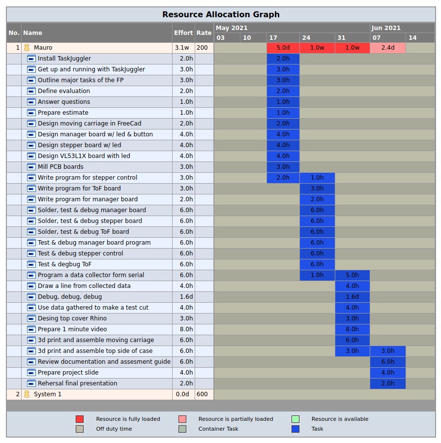
Once the project fitted into the available time, it took me a while to figure out how to get the reports. Probably was the least obvious, and I felt it was not so well documented as the first part. But after some tweaking, I got outa nice Gant Chart, a tasks list and a quite detailed resources allocation. Everthing is conveniently presented in html format.
One of the reports that I found more interesting was the Resource Allocation Graph, where, as it can be seen below, it is going to be a quite interesting couple of weeks...
Overall, I really liked how the program works. I will use it while doing the final project, for tracking purposes. In my opinion, there is where most of this type of tool prove less useful.