Week10
Intput device
Go to:Group assignment Individual assignment
Group assignment
Probe an input device(s)'s analog and digital signals
Document your work (in a group or individually)
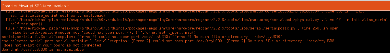
For this group assignment I measure the board I have just produced this week. To do that with the oscilloscope, I first tried to measure while the board was transmitting to the arduino IDE monitor, NOT a good idea. I think I have just burned the attiny412, not once or twice but three times, I can not load any other programs now and I get an error. It's only after talking to Adrian about it that I realized, I should not use the monitor while probing.
I also forgot to put the capacitor that protects the board (1uf) probably one of the reason I burned the microcontroller.
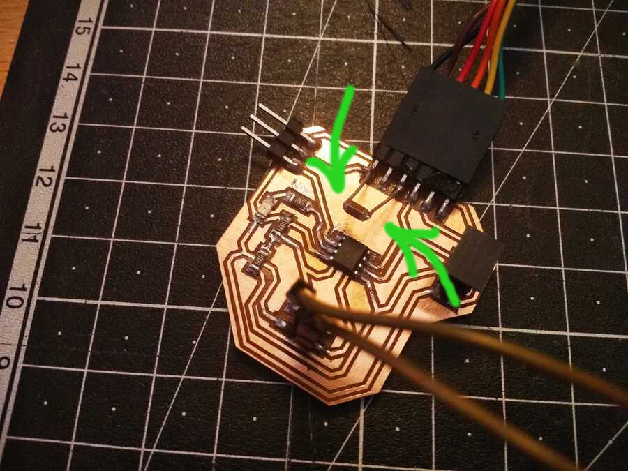
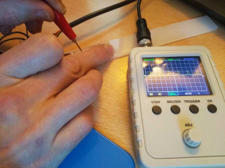
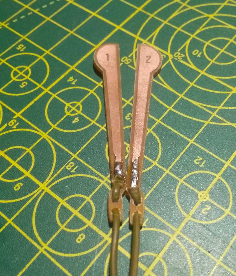
To measure with the Oscilloscope, I need to power the board with GND and VCC (5v), and connect the probe of the oscilloscope to GND and the analog or digital pins (in my case I will be probing the electrodes, 1 digital and 2 analog).
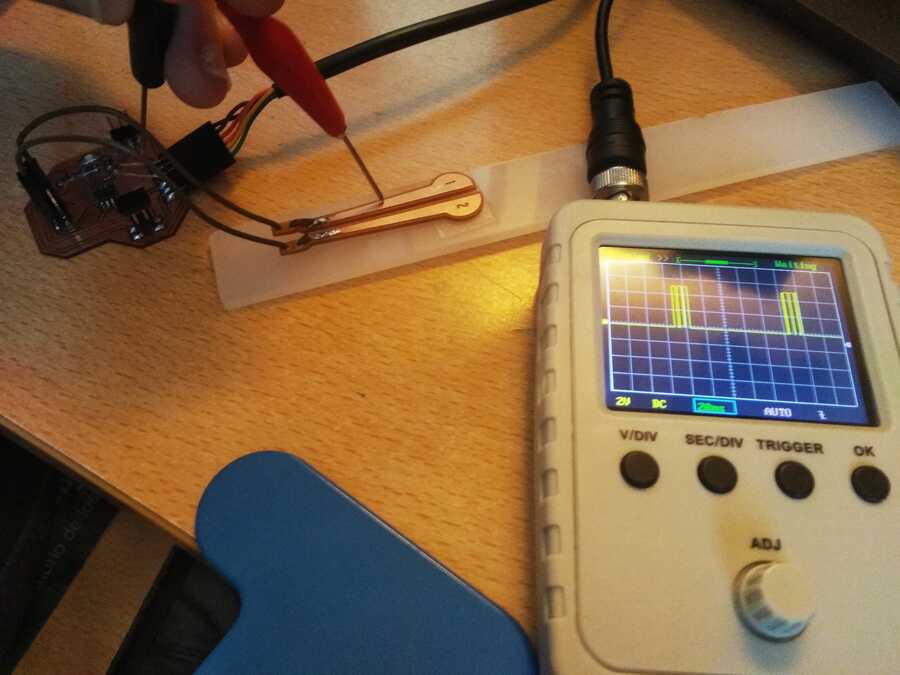
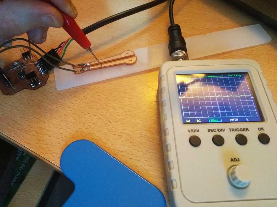
I see the signal changing when I touch it...
Go to:Group assignment Individual assignment
Individual assignment
Measure something: add a sensor to a microcontroller board that you have designed and read it.
I started with Eagle on ubuntu this time, as I wanted to see the differences with fusion360, I also noticed that autodesk is slowly taking away features from the education licence and I would like to have alternatives. I am trying to test things and find out more information for my final project regarding the input. I will try to make a simple step response board. I have more of the tiny 45 but I have never used the 412, so I think I will try to use one of thoses...
In Eagle I loaded the libraries (same used in the previous weeks with fusion) since it was the first time using it on this computer. To start the schematic I looked at Neil´s step response board, here is an interesting use that was shown in class and this particular one that has an interesting integration of the electrode.
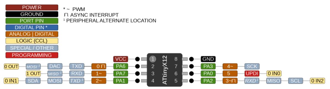
I also took in consideration the advice of the instructors and added extra pins (Tx, Rx, GND and VCC as shown in this example) anticipating for the networking week assignment. It is also required to swap the pins PA6 (TXD) and PA7 (RXD) for a reason that I do not yet know...
I am also looking at this documentation as I am going to use the ATtiny412 and it is where I got the pin out and this one in order to find out more about it. The datasheet from the vendor web site.
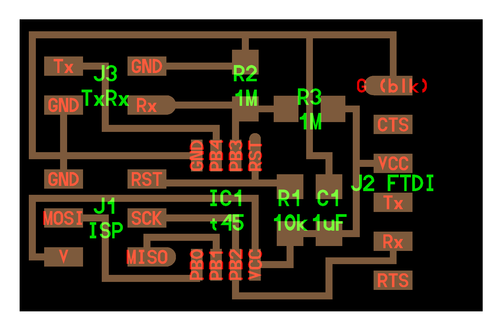
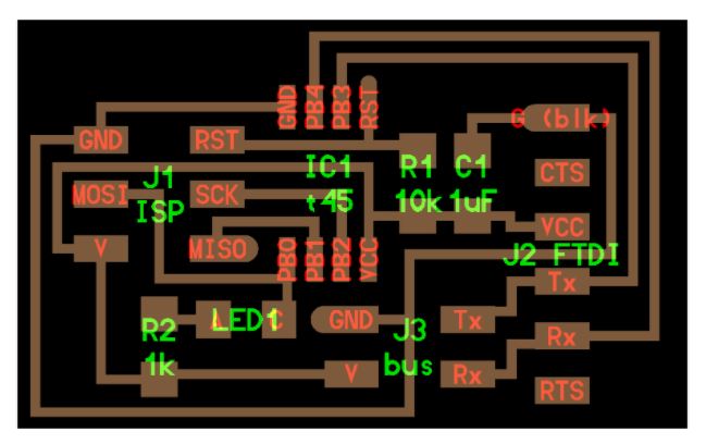
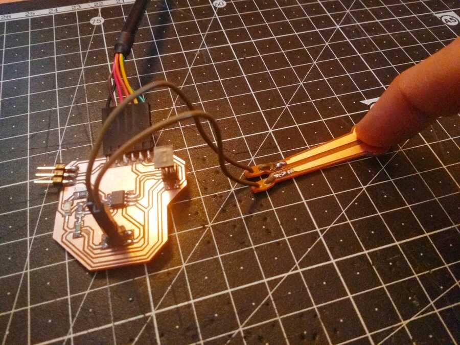
Here is the schematic and routing I came up with
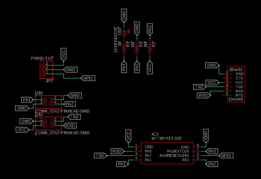
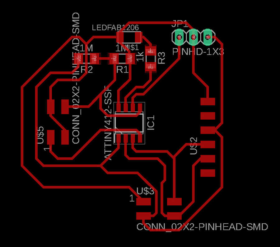
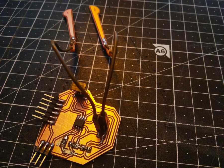
The finished board and electrodes.
The traces.svg, the outline .svg, the .sch and the .brd.
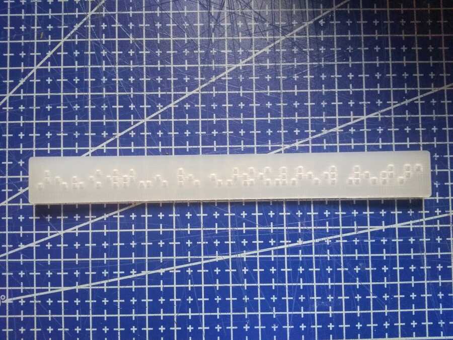
I designed the electrodes in inkscape, not sure it is going to work but I hope to be able to sense through acrylic for a start to make some kind of "button". I would like to be able to trigger a routine just at the end of the braille text (as it is being red with the fingers).
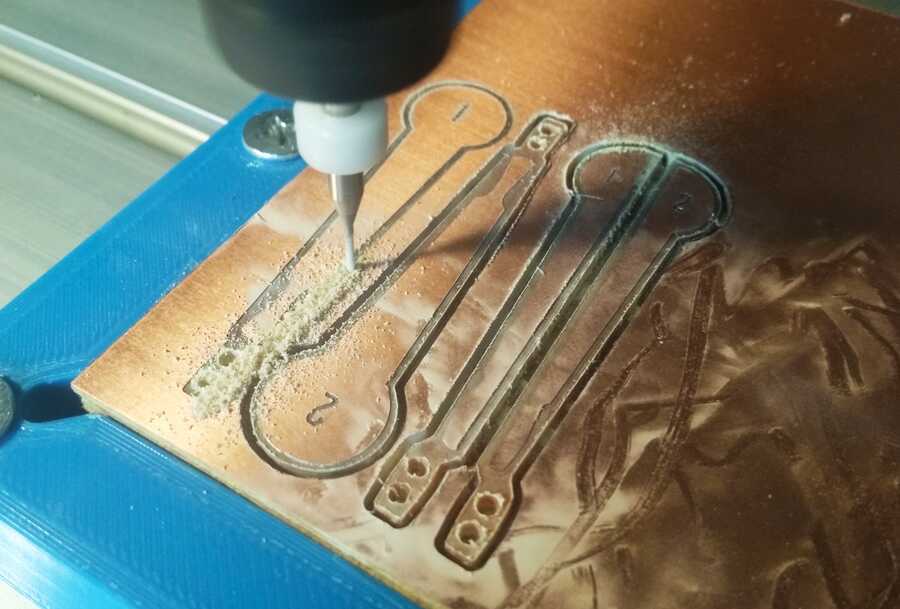
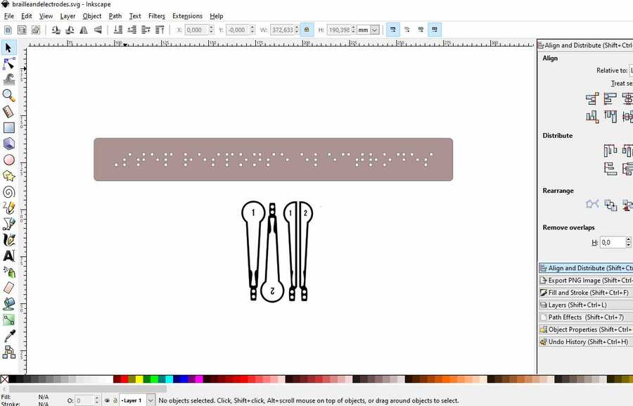
The .svg file.
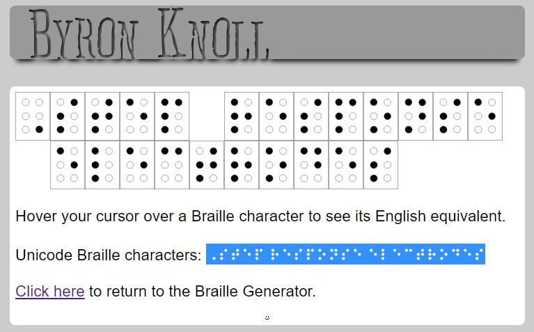
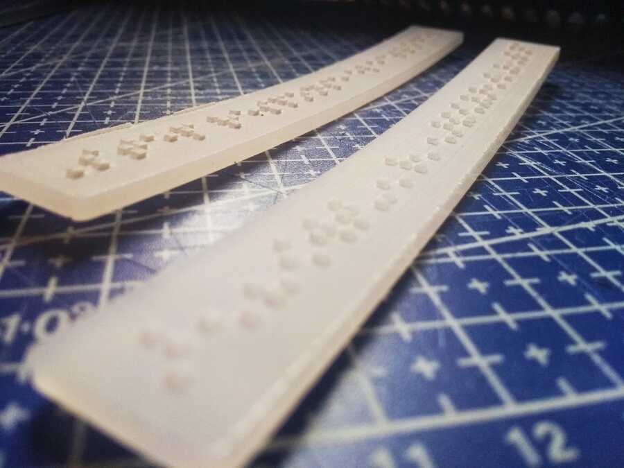
I used an online convertor to get the unicode Braille characters (stating: "step response electrodes"). The acrilic curves and once engraved, it is not really nice to the touch, I must try to use an other material or process or maybe engrave it on a bigger part...
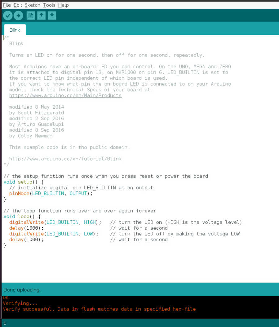
On to the programming, I used the Arduino IDE to first program a simple blink code and see if the board is working...Looking for more info on the programmation, in the link Adrian sent me to his own documentation, I found Robert hart´s documentation, which is where he got the original code. Here is the git hub page with a lot of info on different sensors.
I am able to upload the blink test working fine with the led I added to the board (PA3)...
.jpg)
I then copied Robert´s code, tx_rx, assign the analog_pin to 2 (PA1) and the Tx_pin to 3 (PA2) and uploaded the code successfully.
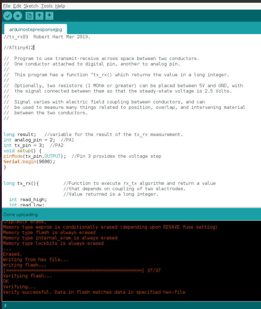
						//tx_rx03  Robert Hart Mar 2019.

						//ATtiny412

						//  Program to use transmit-receive across space between two conductors.
						//  One conductor attached to digital pin, another to analog pin.
						//
						//  This program has a function "tx_rx() which returns the value in a long integer.
						//
						//  Optionally, two resistors (1 MOhm or greater) can be placed between 5V and GND, with
						//  the signal connected between them so that the steady-state voltage is 2.5 Volts.
						//
						//  Signal varies with electric field coupling between conductors, and can
						//  be used to measure many things related to position, overlap, and intervening material
						//  between the two conductors.
						//


						long result;   //variable for the result of the tx_rx measurement.
						int analog_pin = 2;  //PA1
						int tx_pin = 3;  //PA2
						void setup() {
						pinMode(tx_pin,OUTPUT);  //Pin 3 provides the voltage step
						Serial.begin(9600);
						}


						long tx_rx(){         //Function to execute rx_tx algorithm and return a value
												//that depends on coupling of two electrodes.
												 //Value returned is a long integer.
							int read_high;
							int read_low;
							int diff;
							long int sum;
							int N_samples = 100;  //Number of samples to take. Larger number slows it down, but reduces scatter.

							sum = 0;

							for (int i = 0; i < N_samples; i++){
							digitalWrite(tx_pin,HIGH);          //Step the voltage high on conductor 1.
							read_high = analogRead(analog_pin);   //Measure response of conductor 2.
							delayMicroseconds(100);            //Delay to reach steady state.
							digitalWrite(tx_pin,LOW);               //Step the voltage to zero on conductor 1.
							read_low = analogRead(analog_pin);    //Measure response of conductor 2.
							diff = read_high - read_low;   //desired answer is the difference between high and low.
							sum += diff;             //Sums up N_samples of these measurements.
							}
							return sum;
							}                   //End of tx_rx function.


							void loop() {

							result = tx_rx();
							Serial.println(result);
							delay(100);


							}
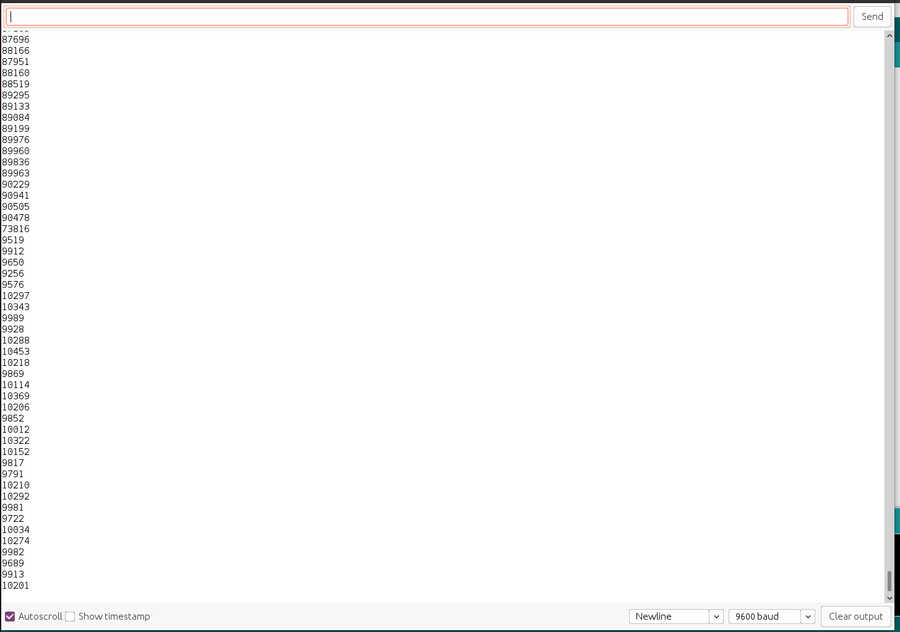
In the serial monitor, I can see if it is transmitting values, the value jumps of a digit (more or less) when I create a bridge between the 2 electrodes with my finger.
Go to:Group assignment Individual assignment
Learning outcomes
Demonstrate workflows used in sensing something with input device(s) and MCU board
Have you?
Linked to the group assignment pageDocumented what you learned from interfacing an input device(s) to microcontroller and how the physical property relates to the measured resultsDocumented your design and fabrication process or linked to previous examples.Explained the programming process/es you used Explained problems and how you fixed themIncluded original design files and source codeIncluded a ‘hero shot/video’ of your board