Week12
Output device
Go to:Group assignment Individual assignment
Group assignment
Measure the power consumption of an output device
Document your work (in a group or individually)
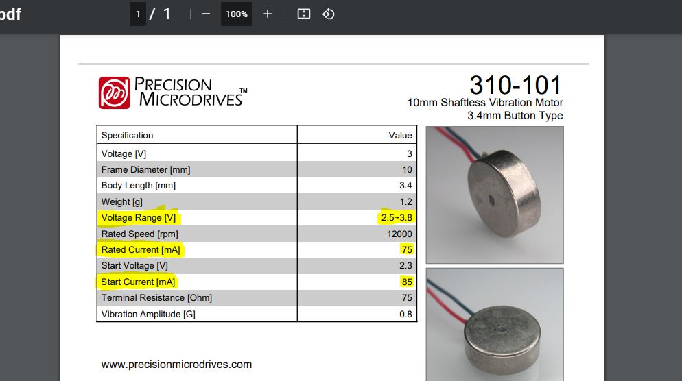
For this group assignment so far, I have only measure the power consumption of the DC motors I am going to use this week and for my final project.
I reusing the datasheet to know what to expect, in my case, we should see about 0,80mA.
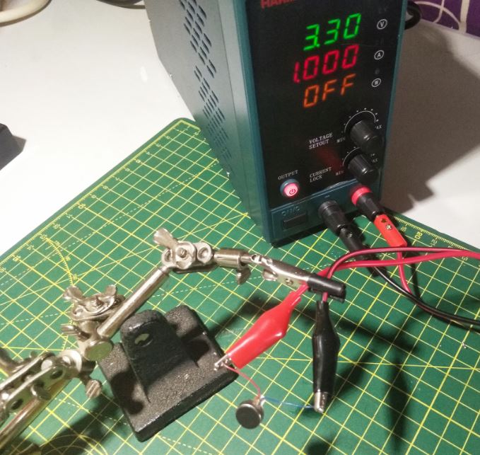
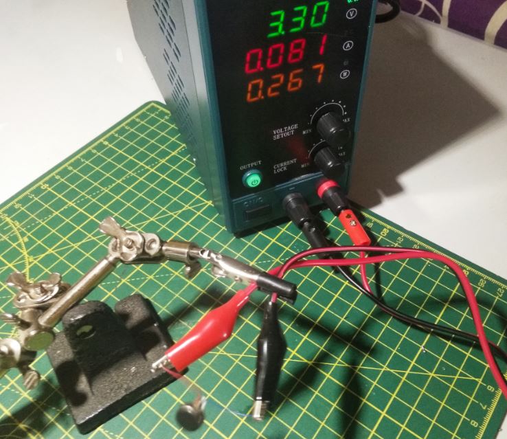
To do that I used a bench power supply, I set the voltage to 3.3v (what we used in week8) and limited the current to 1A (should be enough). The power supply directly shows the current beeing used by the motor when switching the power on, in my case, 0.8mA.
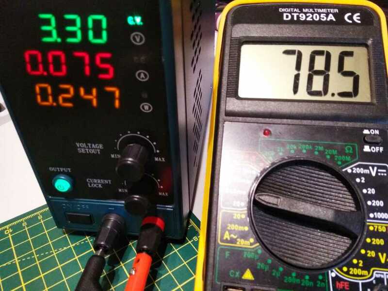
UPDATE: I am adding a comparation between the power supply and the multimeter that I conected in serie.
And a short video showing the power comsumption of all the board connected for the networking week.
Go to:Group assignment Individual assignment
Individual assignment
Add an output device to a microcontroller board you've designed and program it to do something
This week I picking up the work started in week8 with the motors for my final project. I am starting in eagle, first looking for all the components in Neil´s H-bridge board, and Ahmed´s documentation that was very helpfull.
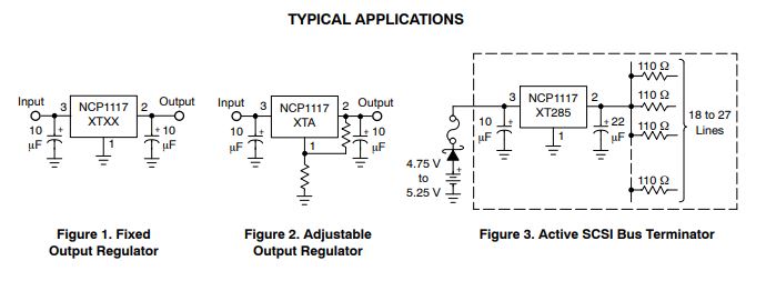
I am using an Attiny1614, same as week8, with an external power supply (9v baterry). So I will be using a voltage regulator NCP1117. In the datasheet, I found examples of the tipical applications.
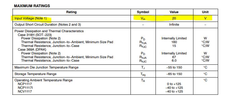
The input maximum voltage.
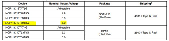
And the output voltage of the partucular package I am using.
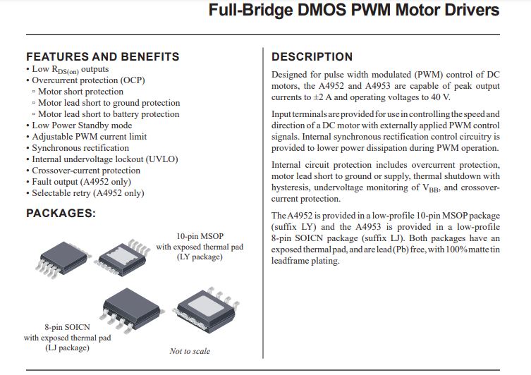
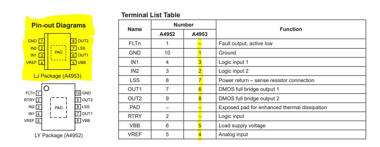
To control the motors, an IC motor controler PWM Allegro A4953.
In the datasheet, I found the pinout.
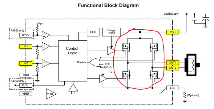
The diagram showing how the "H" bridge is connected, it is composed of x4 mofsets, the "Load supply" (external power supply), the motor output pins OUT1-2 and the IN1-IN2 connecting to the attiny1614 pins to control it.
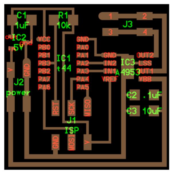
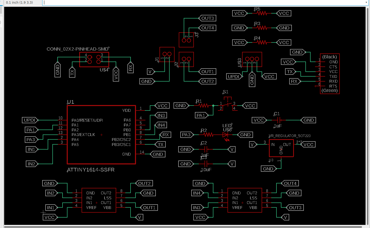
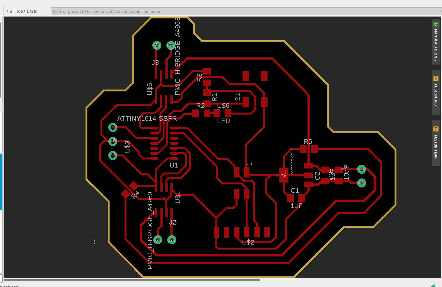
Along with that goes x3 capacitors, x1 (1uf) to protect the 5v part of the board after the regulator, x2 (1uf - 10uf) for the external power supply part of the board. x3 pins, UPDI, GND and VCC to program it. A conector for the FTDI cable to check if everythung is working, I am adding along with that the communication pins for next week (TX, RX, GND and VCC), same as in week10. Finally I am adding a LED and a pushbutton to make things easier to debug in case things don´t work out.
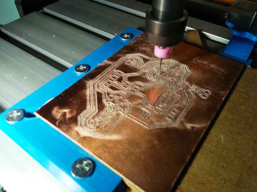
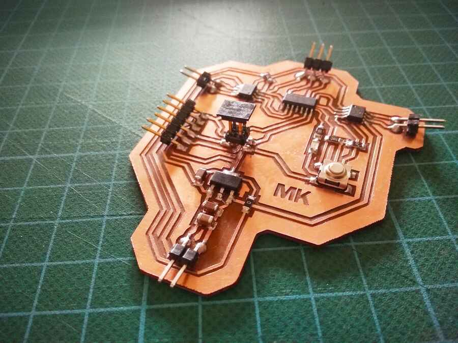
Here is the schematic, routing, some of the milling and the final board.
The .SVG fileThe .SVG shape fileThe .SCH fileThe .BRD file
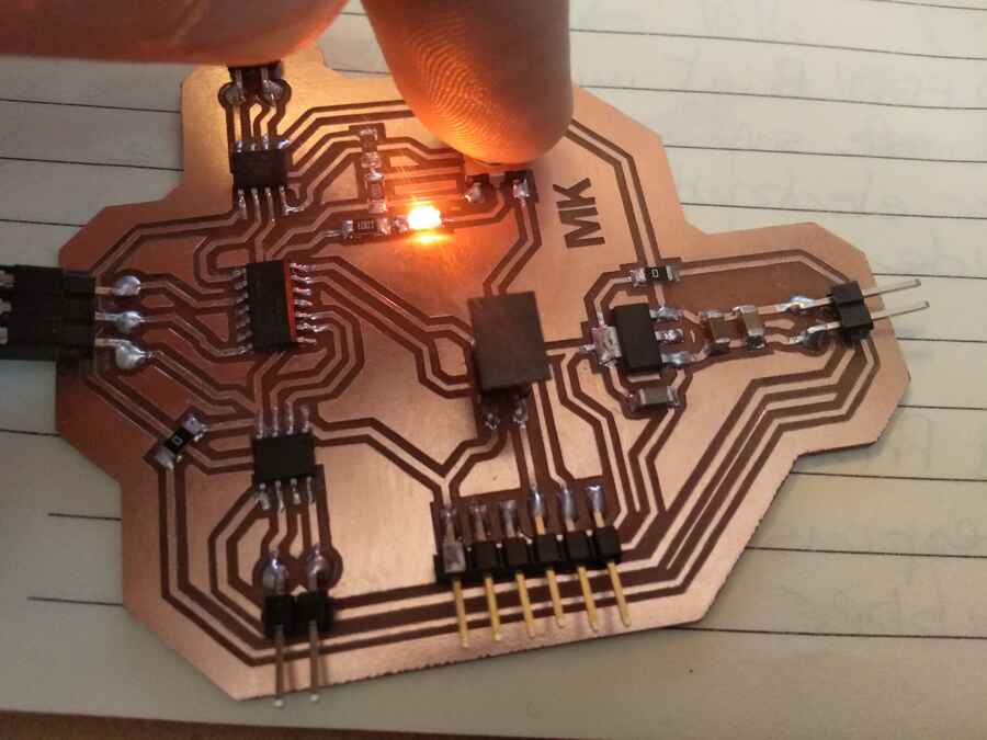
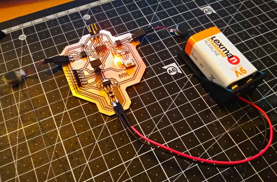
A quick test with the button and LED and a 6v power supply to make sure I can program it with no issues, so far so good...
I have soldered female connector pins to the power source and motors to make it easier...
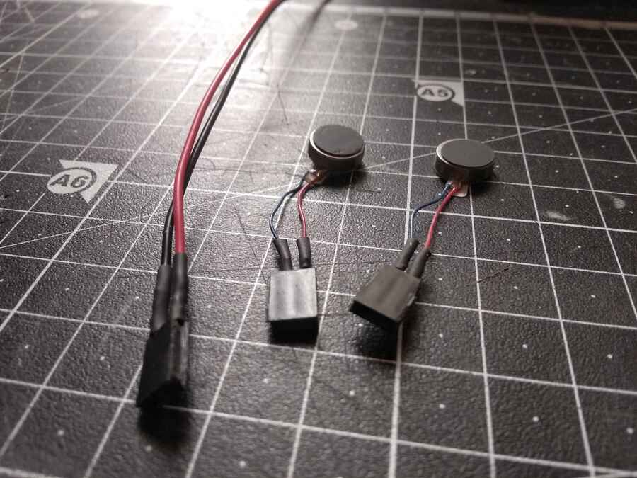
try to make sence of Neil´s code but tested with a 9v battery and a much simpler code first, I started testing only one motor at the time, then both with the LED. Here is the code so far...
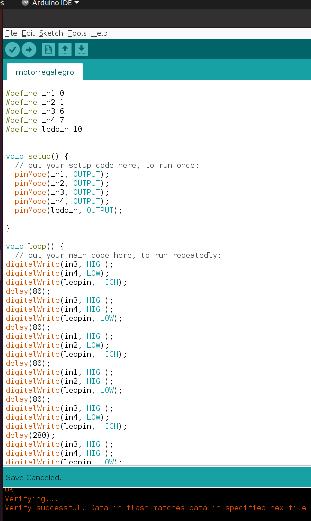
						  #include
						    //define the pins and their names
							#define in1 0
							#define in2 1
							#define in3 6
							#define in4 7
							#define ledpin 10


							void setup() {
							// put your setup code here, to run once:
							pinMode(in1, OUTPUT);
							pinMode(in2, OUTPUT);
							pinMode(in3, OUTPUT);
							pinMode(in4, OUTPUT);
							pinMode(ledpin, OUTPUT);

							}

							void loop() {
							// put your main code here, to run repeatedly:
							digitalWrite(in3, HIGH);
							digitalWrite(in4, LOW);
							digitalWrite(ledpin, HIGH);
							delay(80);
							digitalWrite(in3, HIGH);
							digitalWrite(in4, HIGH);
							digitalWrite(ledpin, LOW);
							delay(80);
							digitalWrite(in1, HIGH);
							digitalWrite(in2, LOW);
							digitalWrite(ledpin, HIGH);
							delay(80);
							digitalWrite(in1, HIGH);
							digitalWrite(in2, HIGH);
							digitalWrite(ledpin, LOW);
							delay(80);
							digitalWrite(in3, HIGH);
							digitalWrite(in4, LOW);
							digitalWrite(ledpin, HIGH);
							delay(280);
							digitalWrite(in3, HIGH);
							digitalWrite(in4, HIGH);
							digitalWrite(ledpin, LOW);
							delay(280);
							digitalWrite(in1, HIGH);
							digitalWrite(in2, LOW);
							digitalWrite(ledpin, HIGH);
							delay(280);
							digitalWrite(in1, HIGH);
							digitalWrite(in2, HIGH);
							digitalWrite(ledpin, LOW);
							delay(280);

							}
						  }
Here is a quick video clip, it looks like this should be fine for my final project, just need to figure out how to incorporate x3 more motors and the audio (more on that in Development).
Go to:Group assignment Individual assignment
Learning outcomes
Demonstrate workflows used in controlling an output device(s) with MCU board you have designed
Have you?
Linked to the group assignment pageDocumented how you determined power consumption of an output device with your groupDocumented what you learned from interfacing output device(s) to microcontroller and controlling the device(s)Described your design and fabrication process or linked to previous examples.Explained the programming process/es you used.Outlined problems and how you fixed themIncluded original design files and code
Included a ‘hero shot/video’ of your board