Week5
3D scaning and printing
Go to:Group assignment Individual assignment
Group assignment
Machine and tools
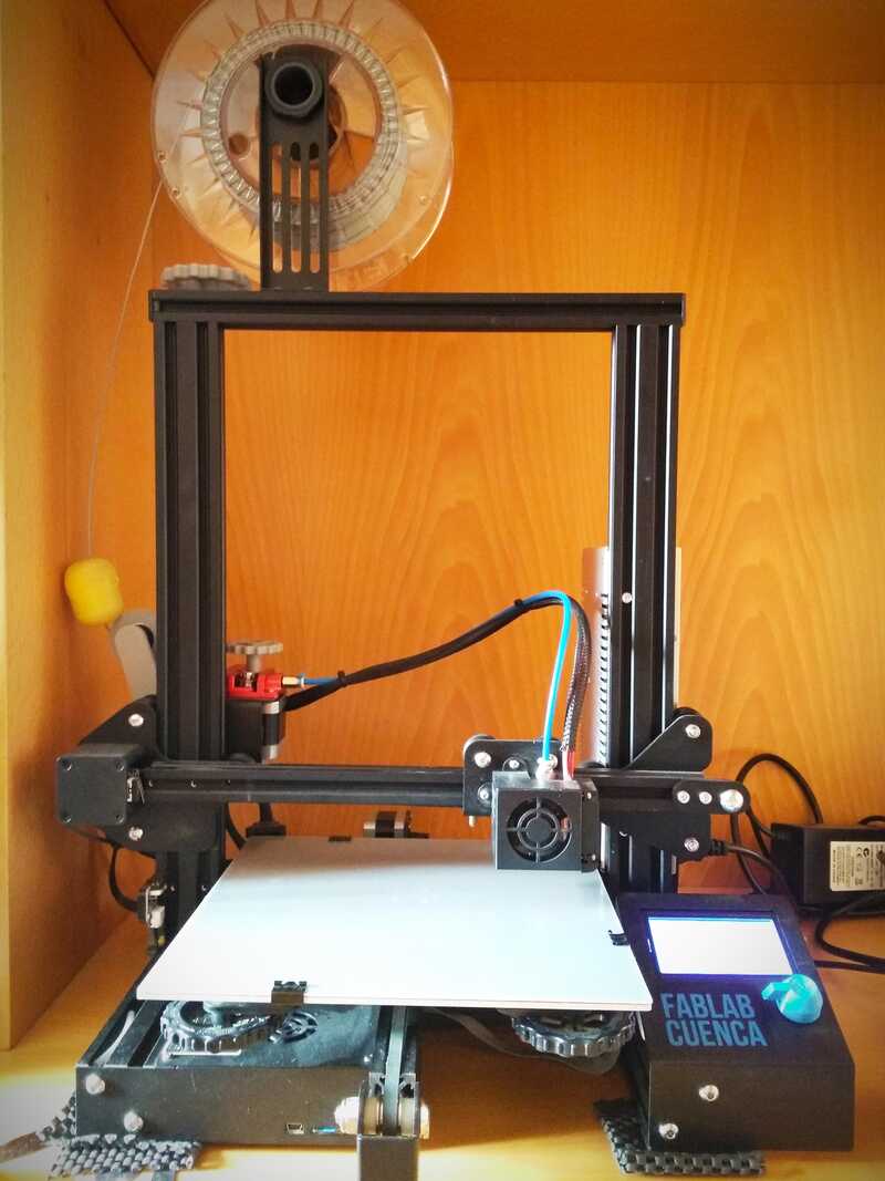
For this assignment I am using the Ender 3. We do have different types of machines in the lab but I couldn't fit anymore at home. Apart from the delta type, the rest of the (FDM) machines share a very similar workflow. It has been slightly modified (filament guide and filter, stronger spring on the platform, etc...) but works more or less as if it was out of the box.
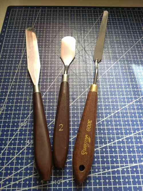
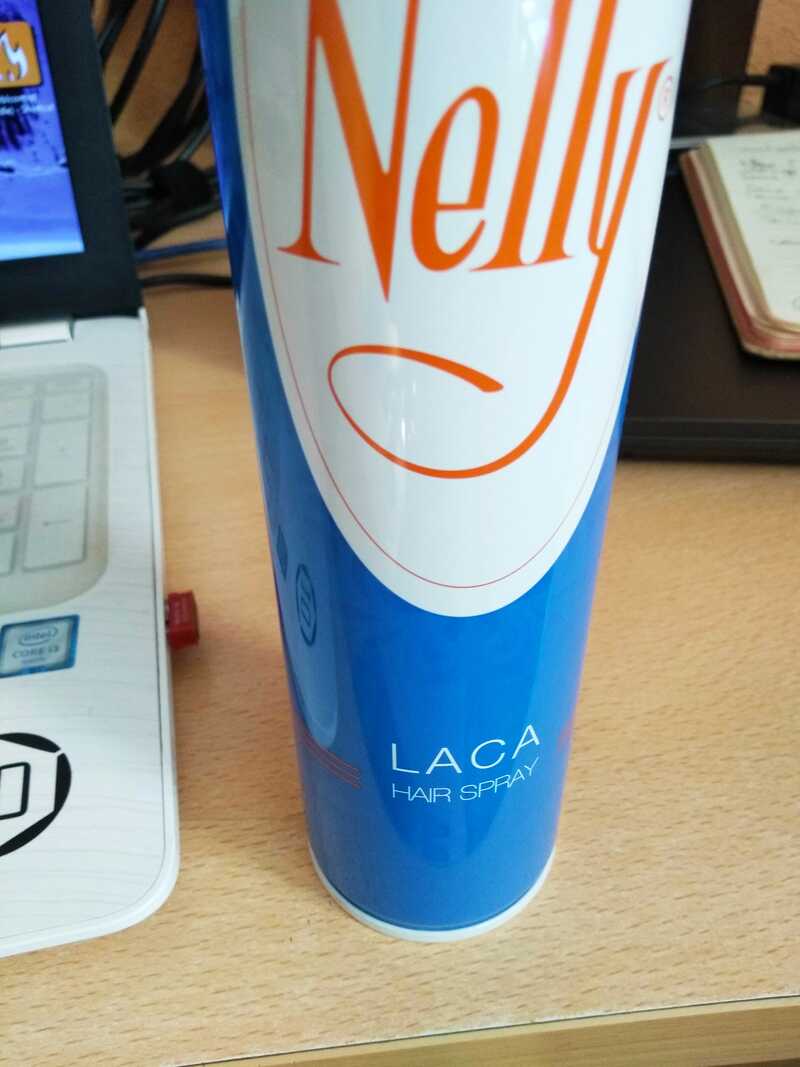
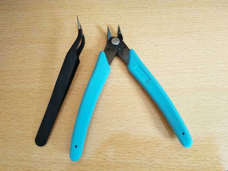
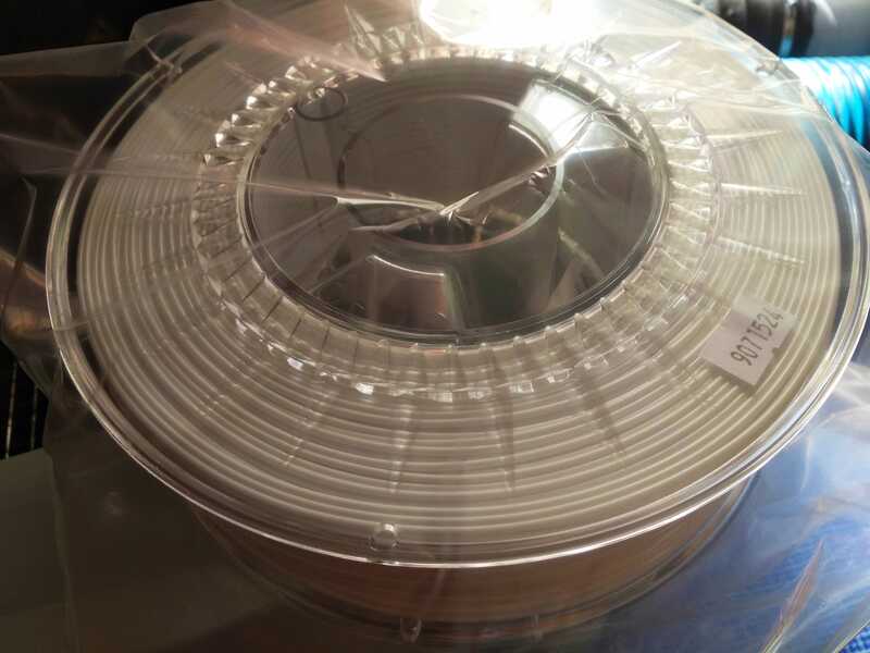
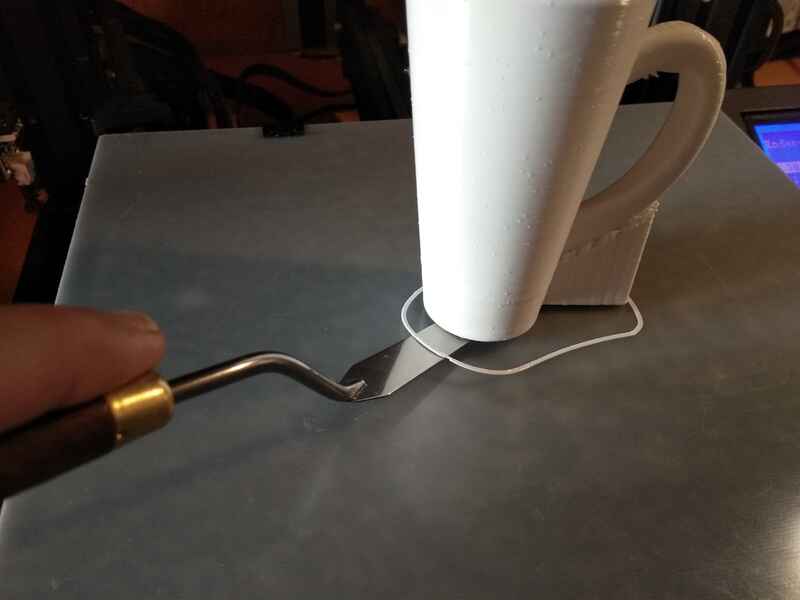
I am using different types of spatulas, so far the best tool I found to separate the part from the platform. Some hair lacquer (depending on the material, it helps the first layer stick to the platform), tweezers, clippers and a roll of PETG filament.
Test the design rules for your printer(s)
First to prepare the g-code, I am using Cura slicer.
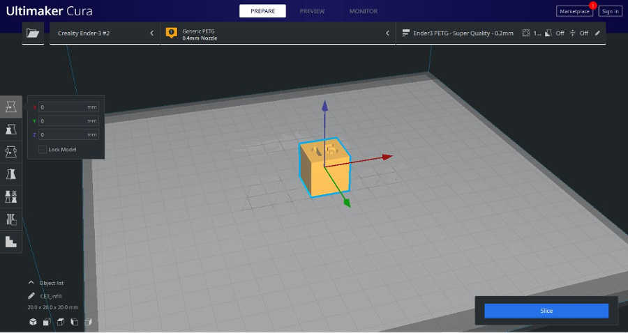
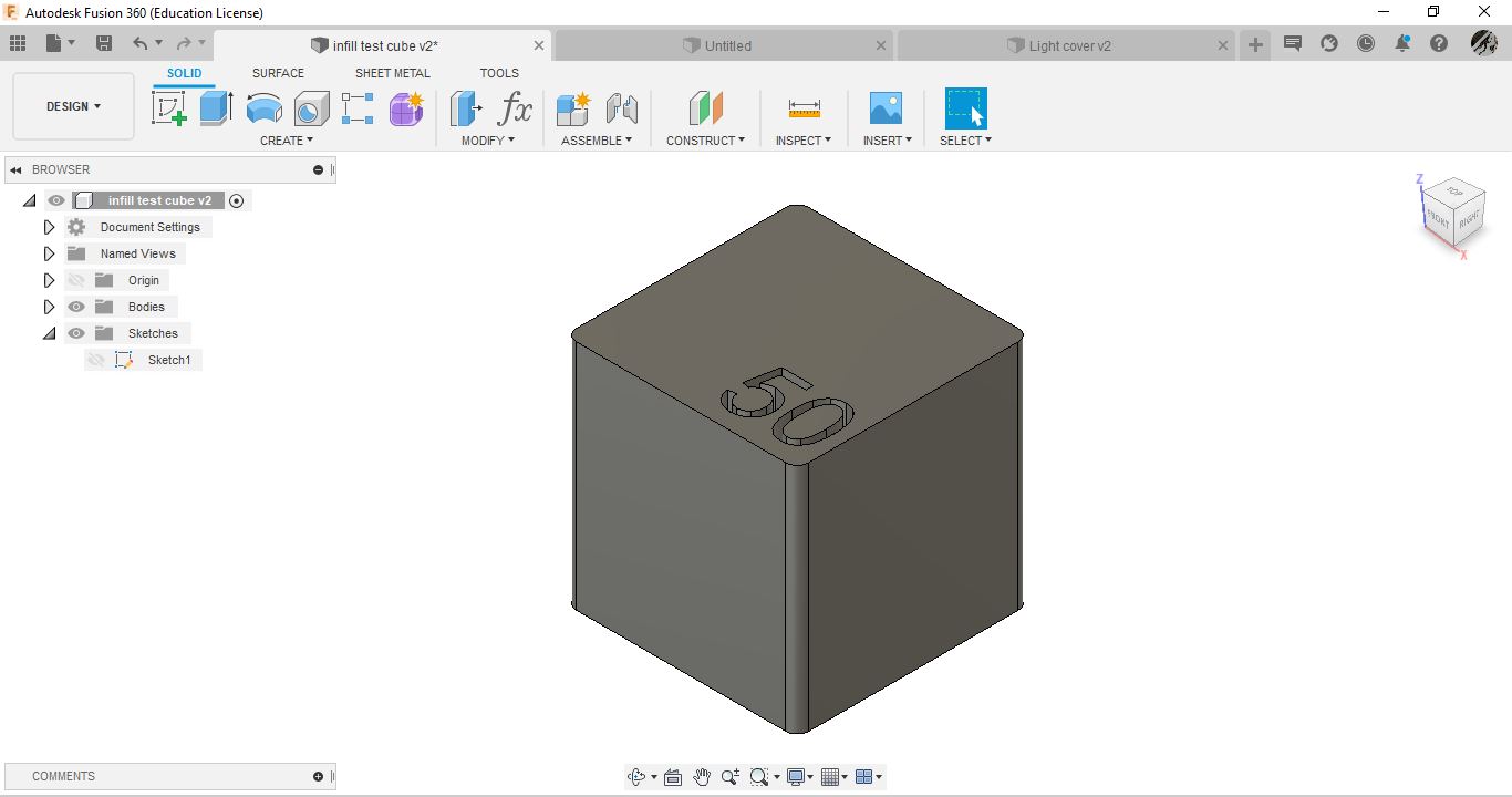
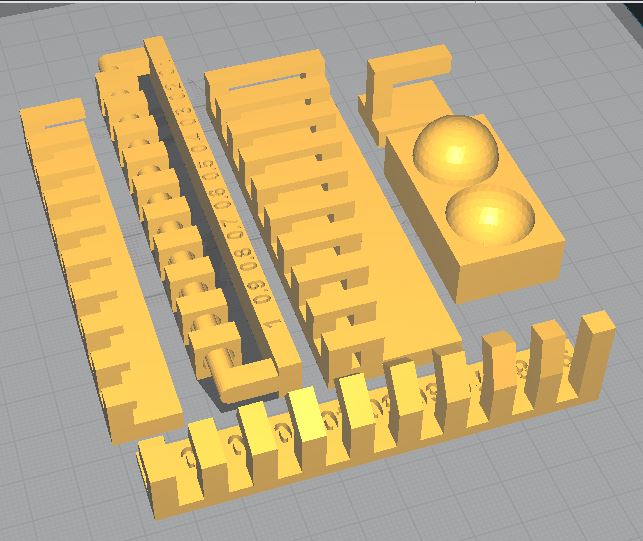
I downloaded the .stl(s) from the course documentation but I re-designed the infill model in fusion.
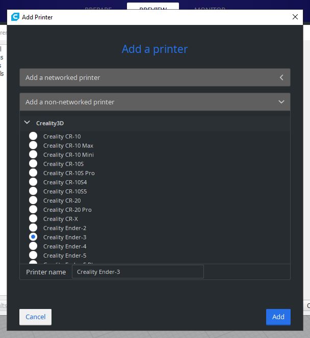
In cura, the profile of this machine is now available in the non-networked printers list under Creality 3D. Find the add printer tools in the setting drop down menu.
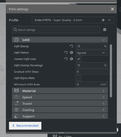
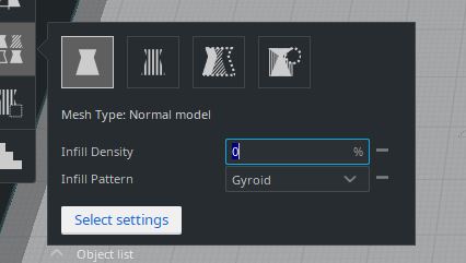
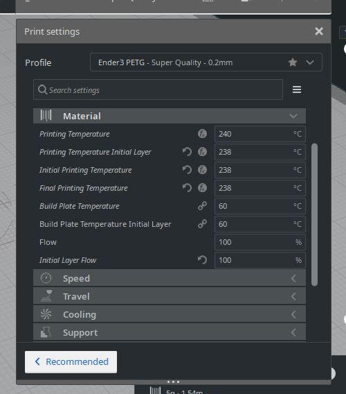
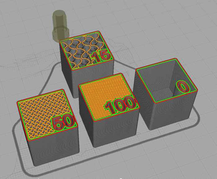
I have personalized the printing profile settings but the recommended section is a good starting point.In my case I will be printing with a layer height of 0.2mm and the model will have x2 0.4mm borders (walls) as well as x2 bottom layers. No top layers and for the infill density, I will be using the "per model settings" option. I set this one at 15% and I will be modifying the rest individually and match the text of each models.
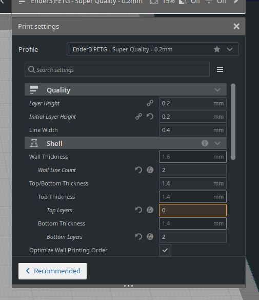
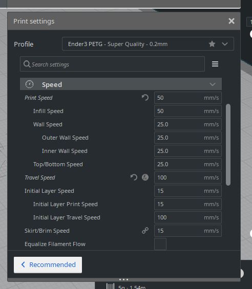
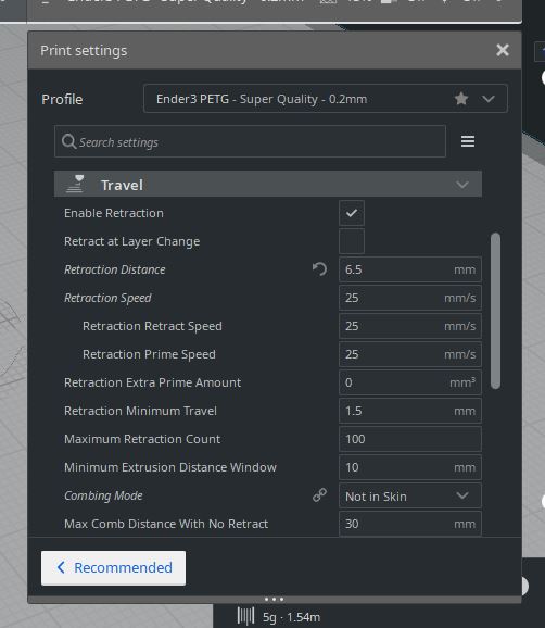
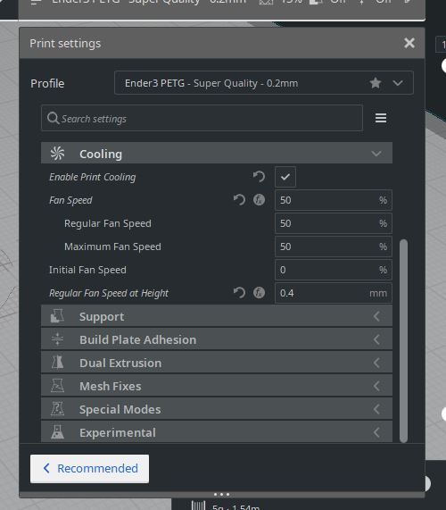
I will be using temperatures between 238°C to 240°C for the nozzle, 60°C for the platform. A printing speed of 50mm/s, 25mm/s outer inner walls and a 100mm/s of travel speed. I start the prints slow at 15mm/s to help make a good adhesion for the first layer. The retraction is on and for this material I am using 6.5mm distance at a speed of 25mm/s, cooling is on at 50%, off for the first layer, no supports and a skirt to prime the nozzle.
These settings are subjective to many factors, they greatly vary depending on the machine state, the quality results needed and the function of the print.I am a big fan of printing on glass, but for these tasks I will be printing on the back of the platform material that comes with the machine, again I like to print on shiny surfaces, this is also one of the reasons I use low printing speeds.
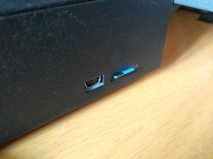
Once the models are sliced I can check the preview and save the g-code onto a mini sd card and back into the machine.
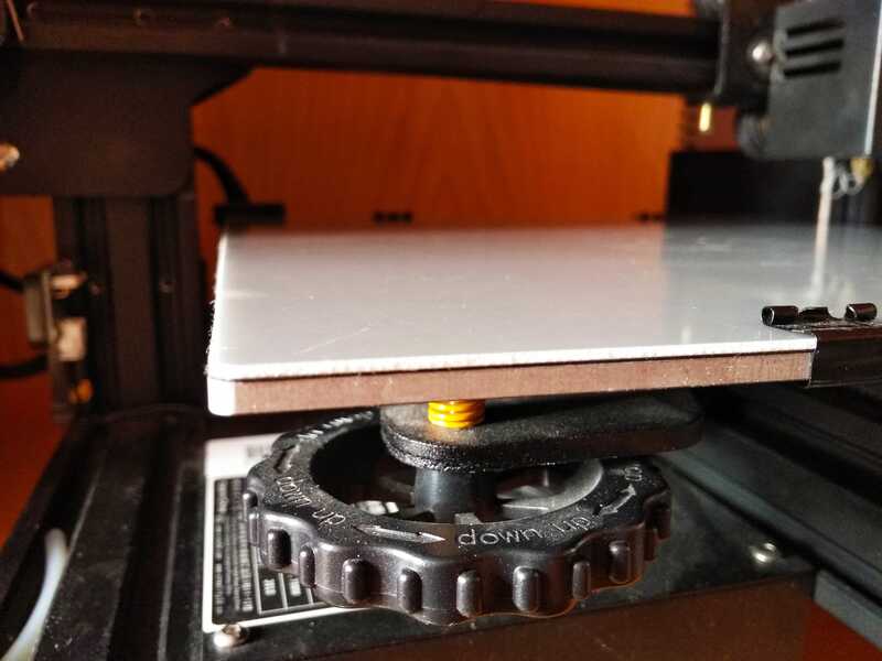
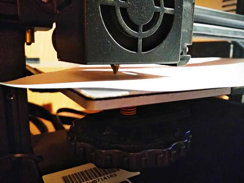
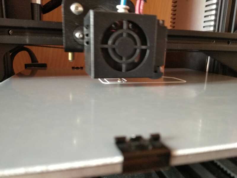
The printing platform needs to be leveled and clean. To level, I basicly leave the thickness of a normal sheet of paper between the nozzle and the platform. I do that above each ajustment nobs around the platform. I always preheat the machine to do the leveling. More about bed leveling here .
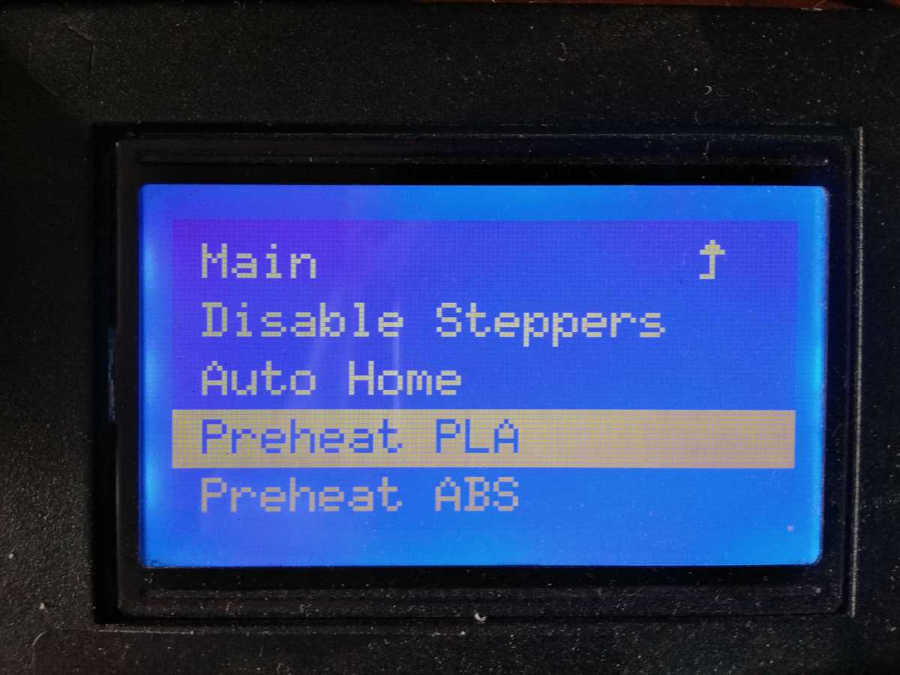
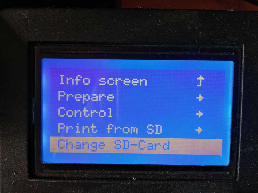
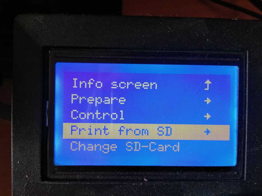
Then, reload (or Init.SD-Card/Change SD-Card) the sd card to finally "print from sd" and select the job.
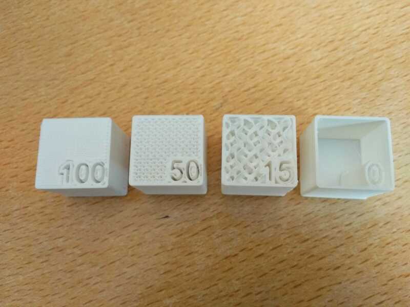
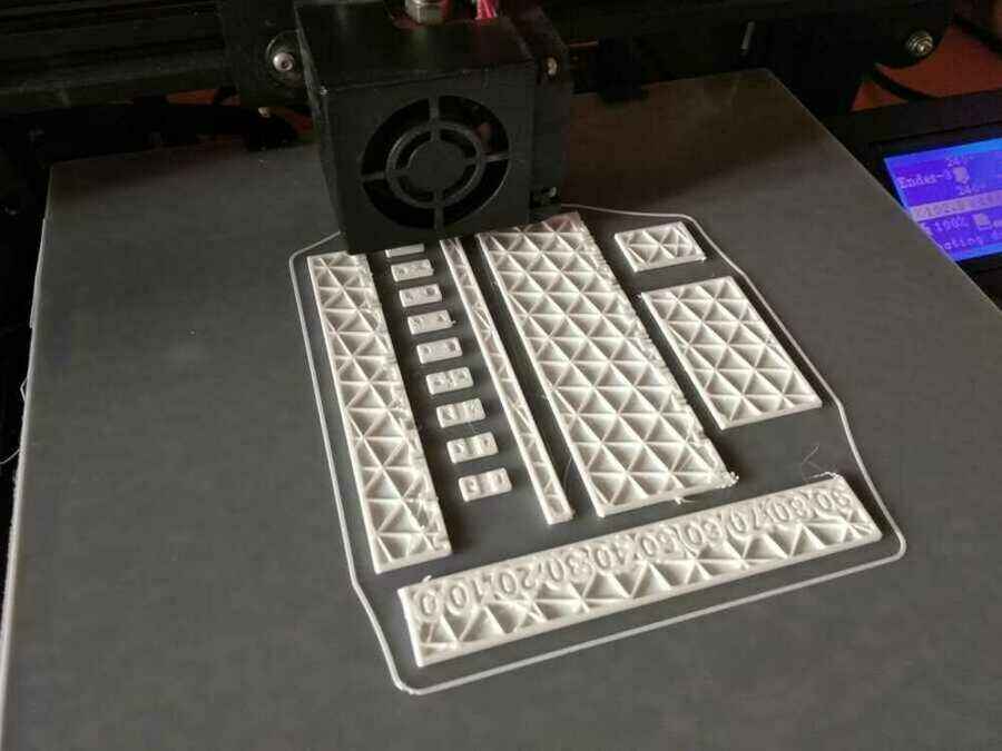
Here is how the prints turned out...
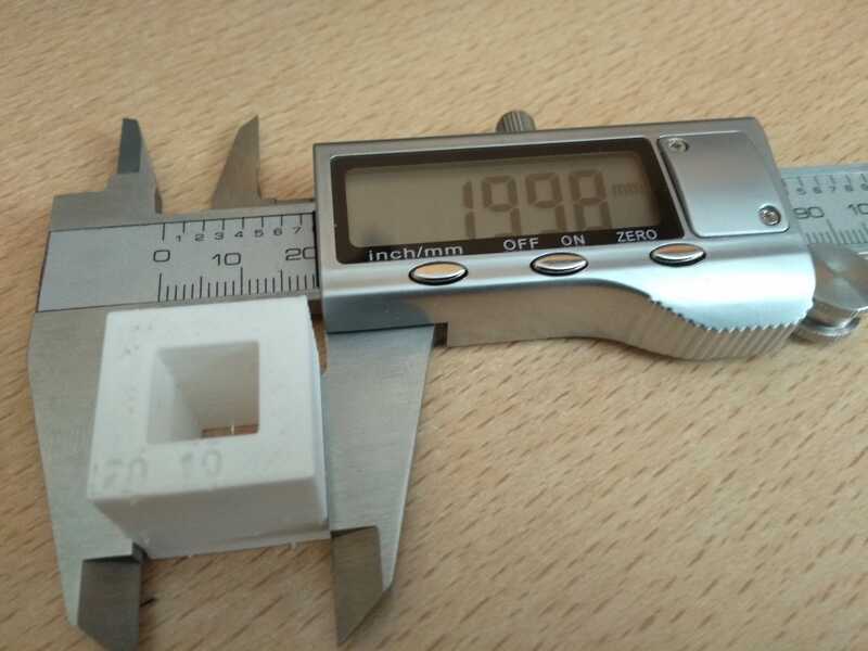
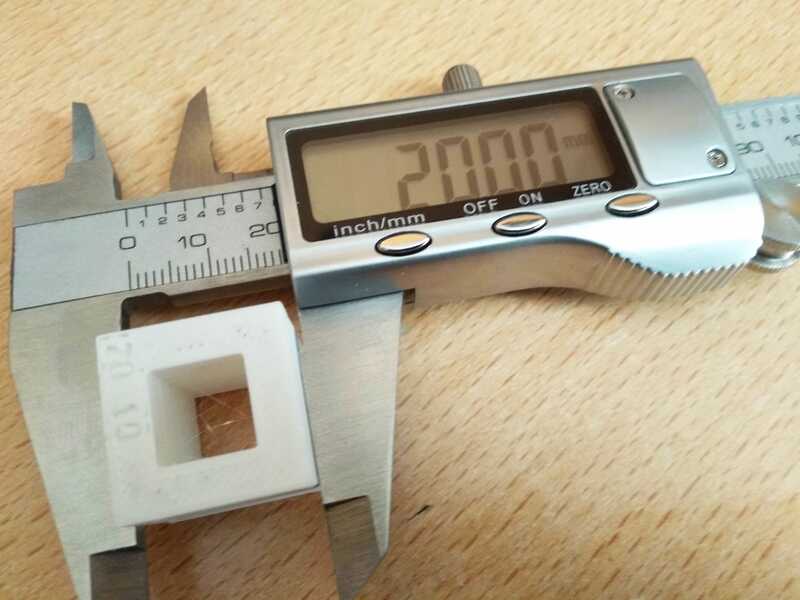
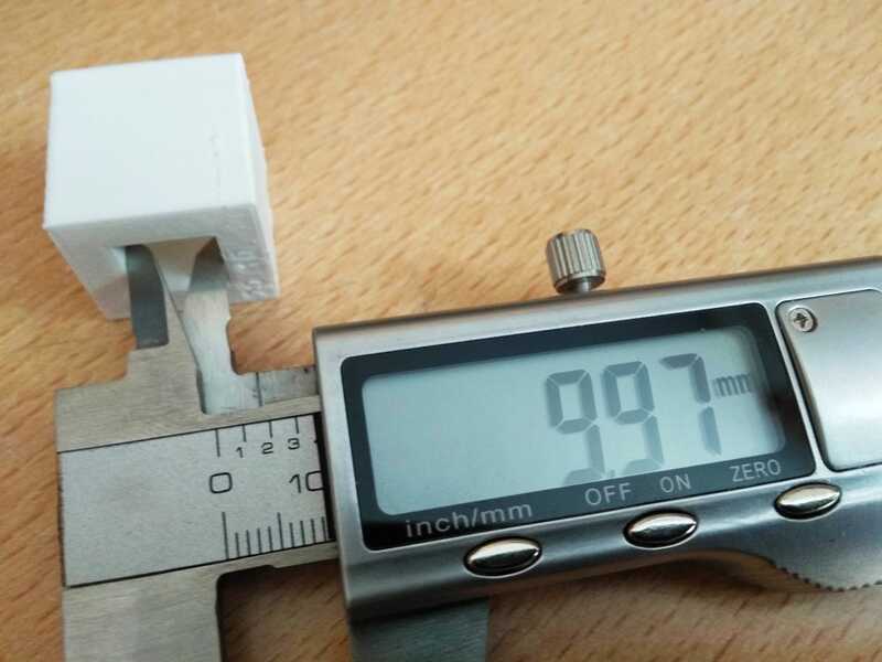
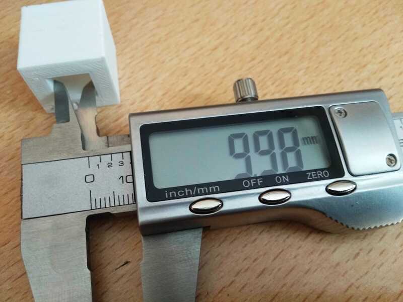
Infill dencity
For the x, y dimension accuracy, on the outer I got a 0.02mm difference on x, nothing on y. For the inner dimensions, I got a 0.03mm on x and 0.02mm on y. considering the material and the size of the model, It's not bad at all.
Now, the rest of the models were printed using the same process.
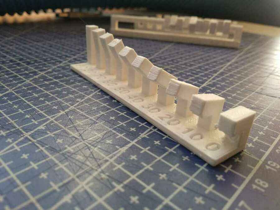
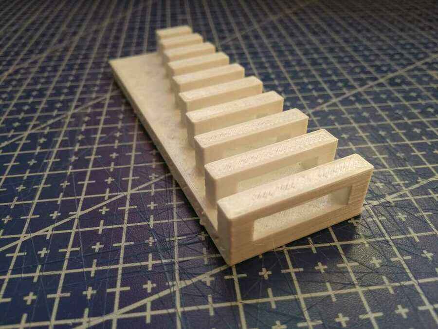
The angle test, seems to be good enough up to 30°
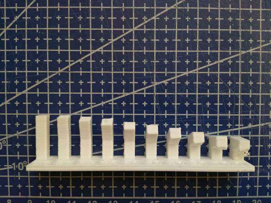
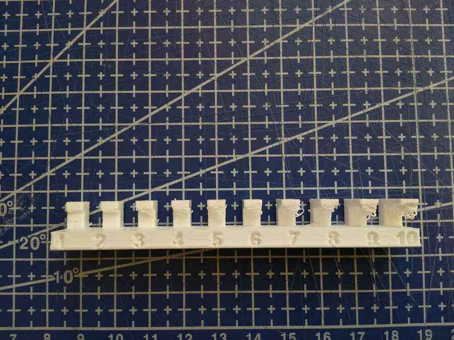
For the overhang, Even a 2mm gap is enough to start deforming the shape and the material falls unsuported.
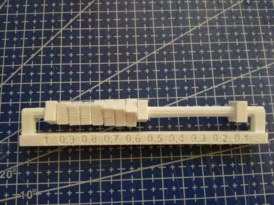
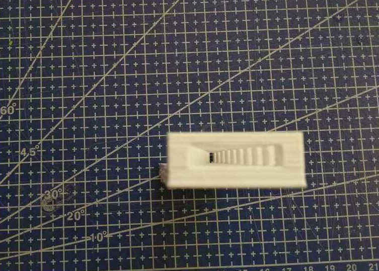
The clearance test, moving but starts to get friction at 0.2mm.
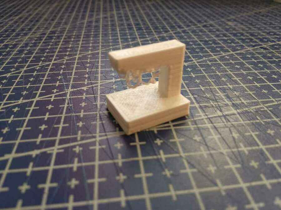
For the Bridging...
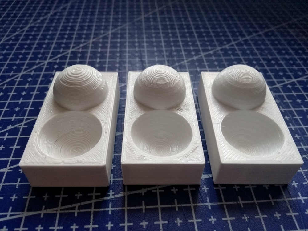
Here are the surface finish tests, from left to right, 0.32mm - 0.2mm - 0.16mm
What are the limits of your printer(s)
I wanted to see how well the printer would perform with PETG and after these tests, I feel that the printer is capable of producing good dimension accuracy. The surface finish could probably be improved but maybe with a smaller nozzle size. For the clearance, I think from 0.28mm on up according to the necessity is fine but depending on the shape and material, I would be comfortable using 0.3mm or maybe even 0.4mm as the clearance in my design.Comparing the angle and the overhang tests, It seem like a good practice to incorporate angles in the design when possible and avoid the need for supports.
Go to:Group assignment Individual assignment
Individual assignment
Design and 3D print an object (small, few cm3, limited by printer time) that could not be easily made subtractively
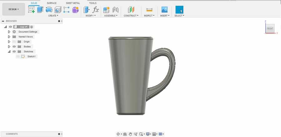
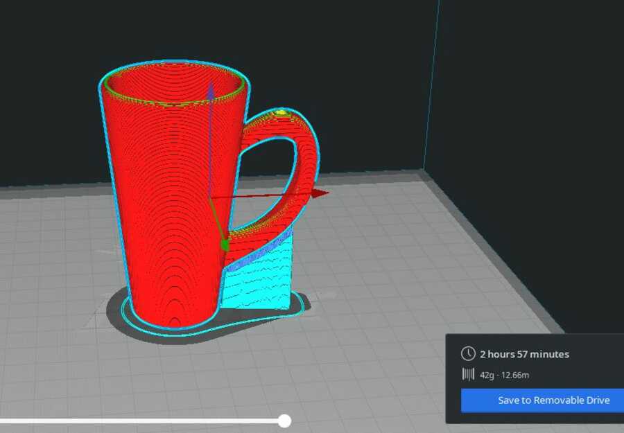
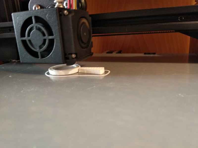
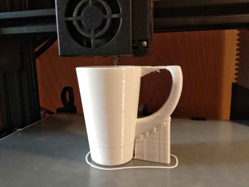
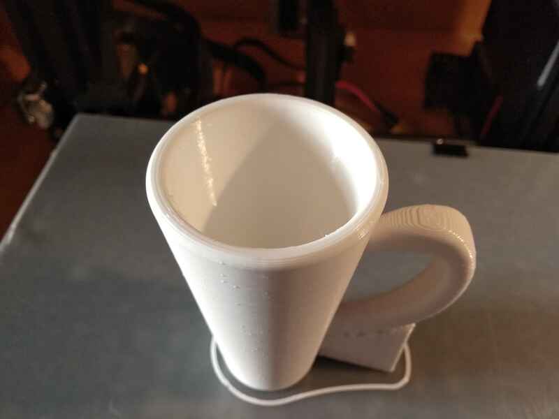
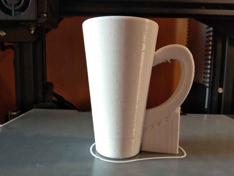
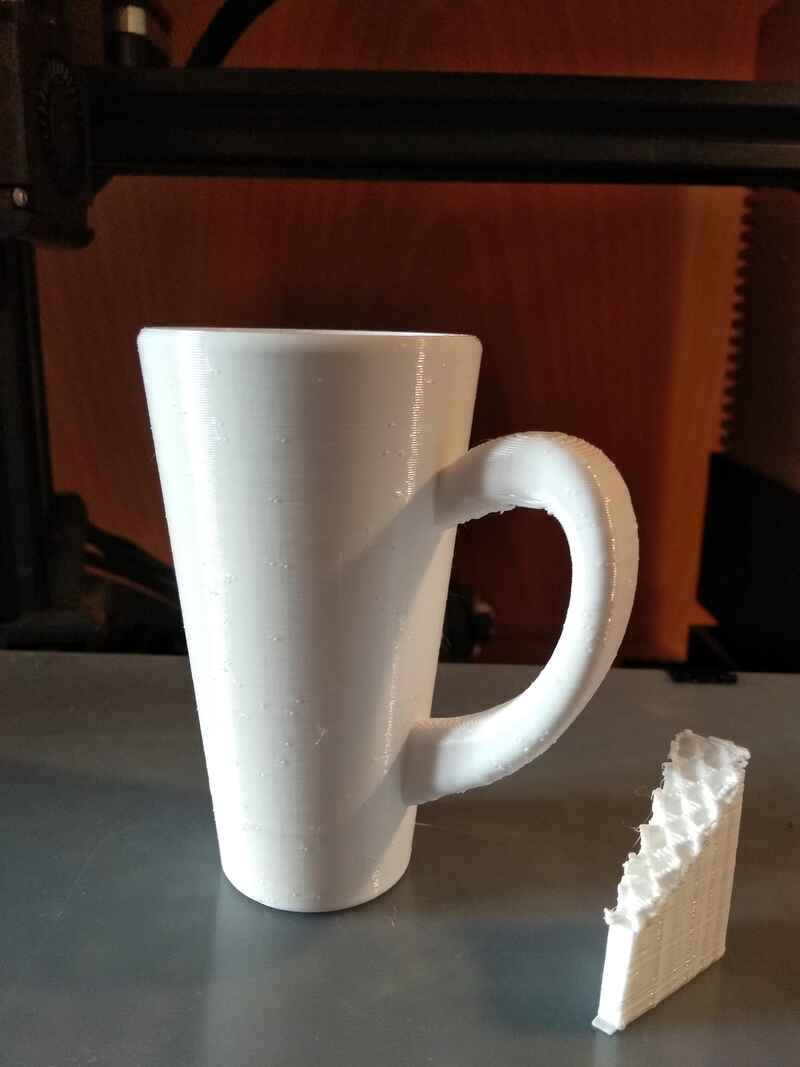
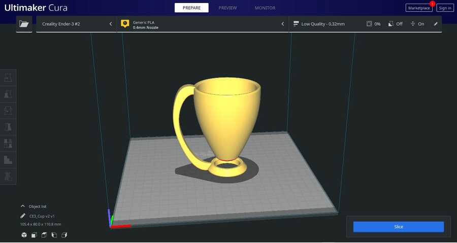
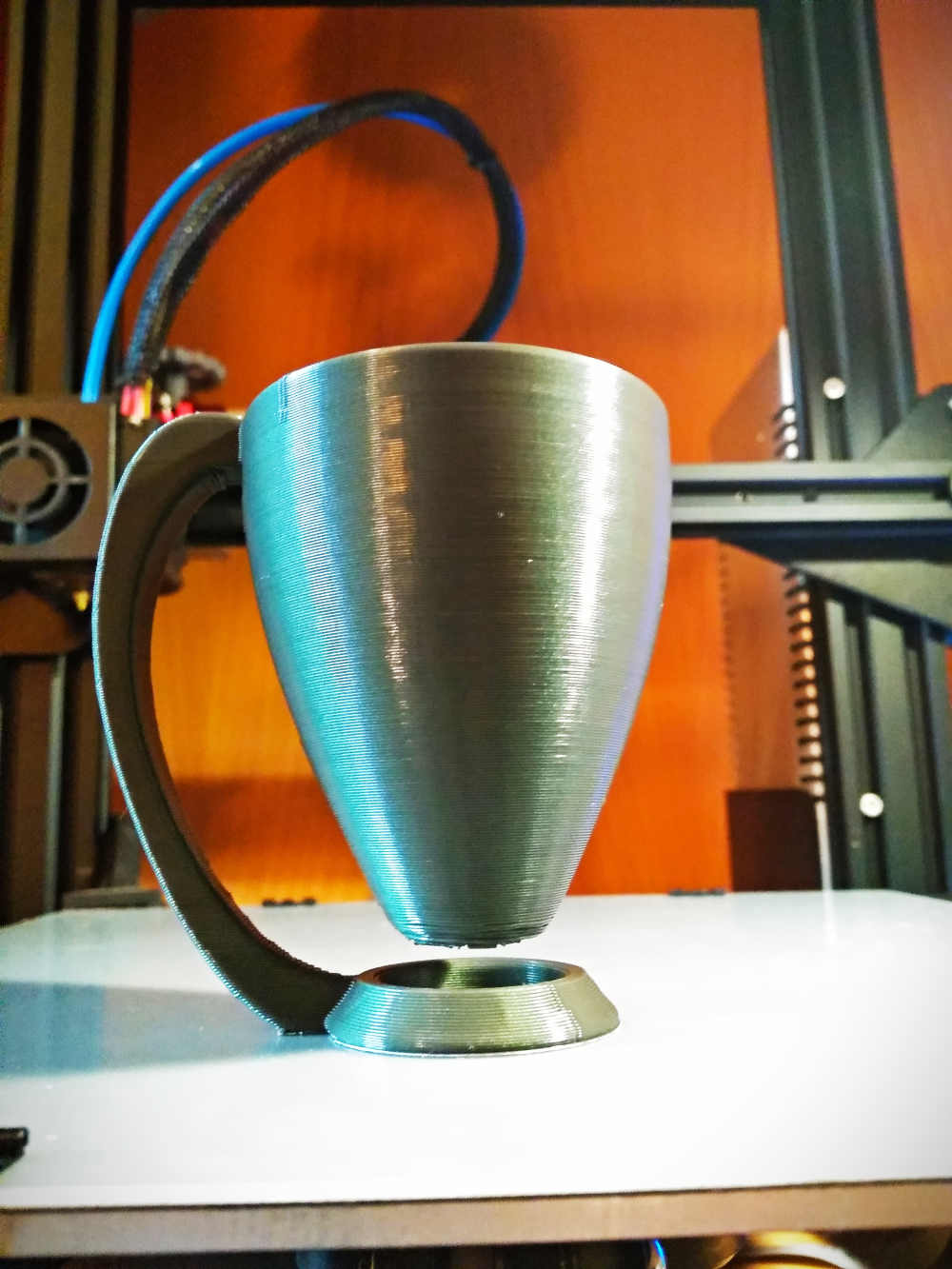
For the design and print, I design a simple cup in Fusion 360 (.f3d), which I am pretty sure would be hard to make with a subtractive machining process (without talking about the function ofcourse). I choose this design because of the overhangs and curves that makes it difficult to mill. I added supports only to the areas that cover the building platform. I also reduced the scale (70%) to help keep the printing time to a minimum.
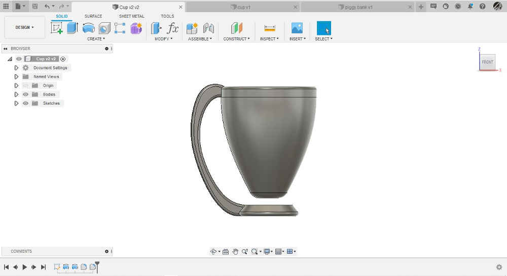
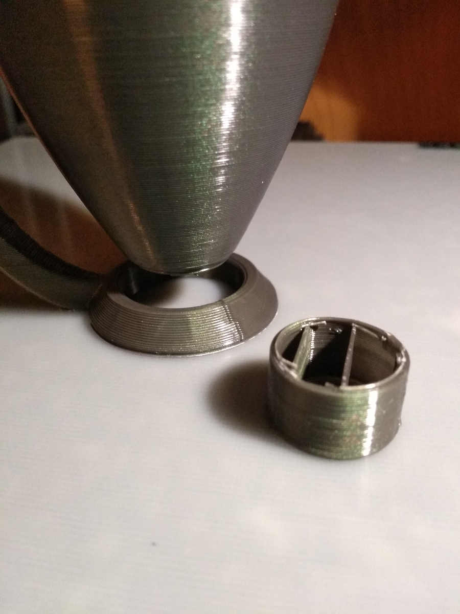
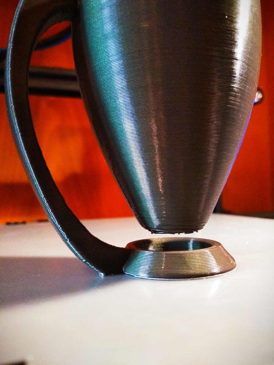
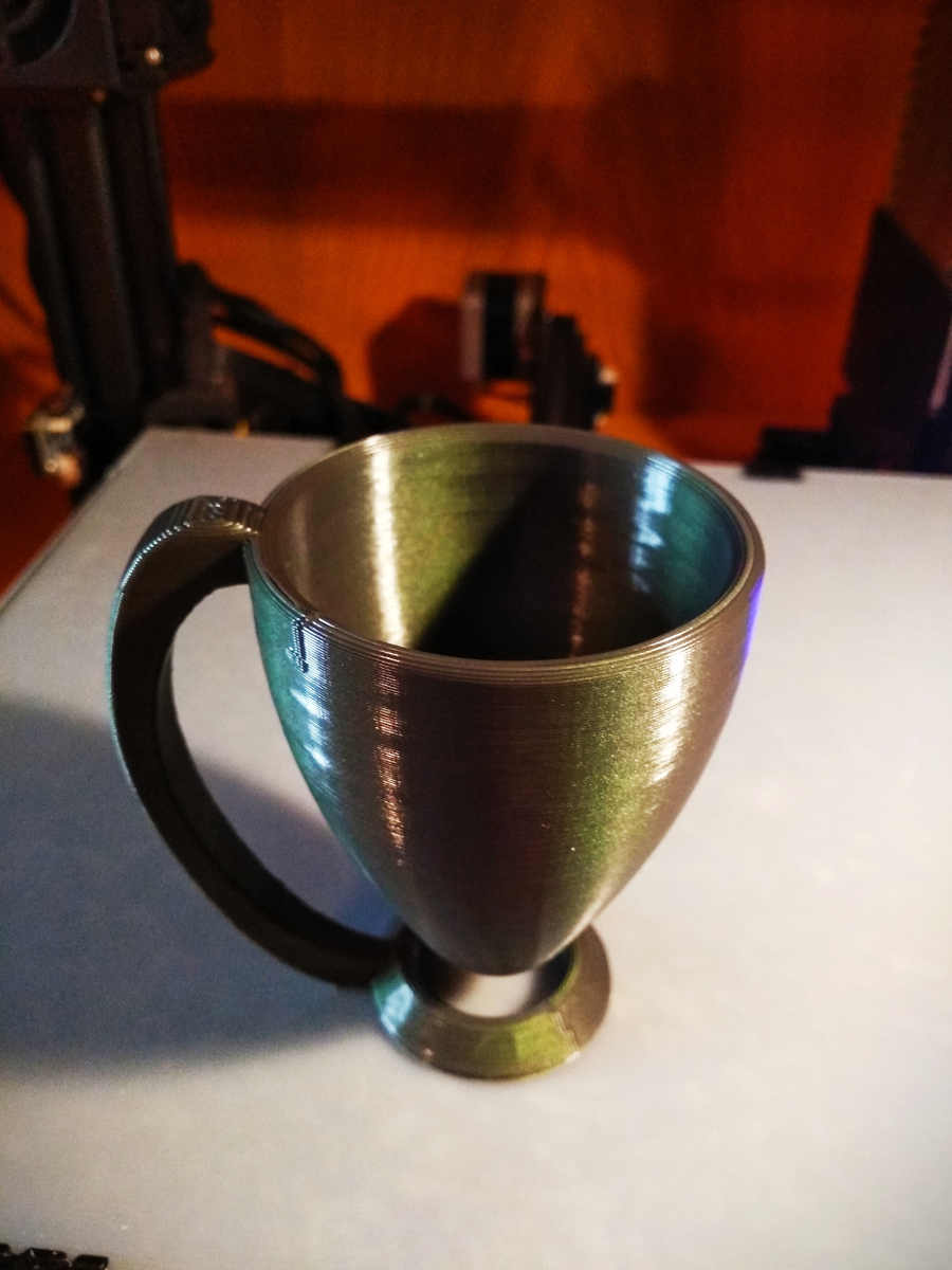
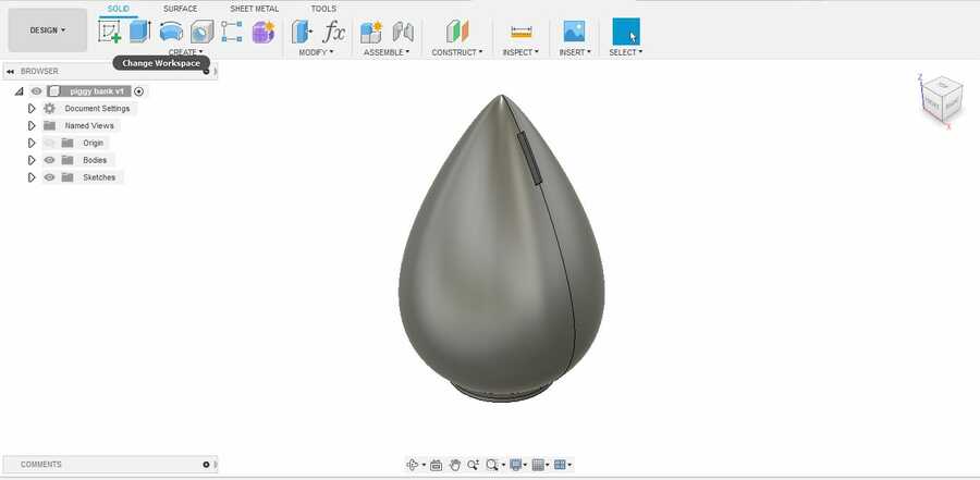
And here is version 2 (.f3d), which I think is even harder to reprodused with substractive processes...
Here are the .STL files.
Another one in which a coin is trapped in the print (cube). I kept an eye for the mid print, and inserted the coin during the print...
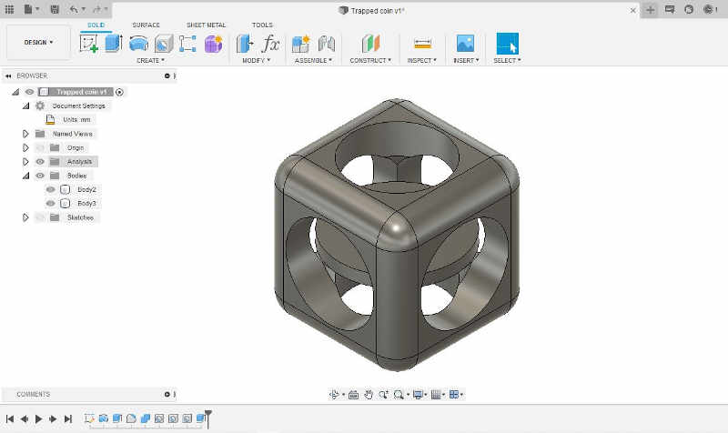
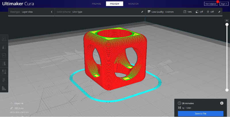
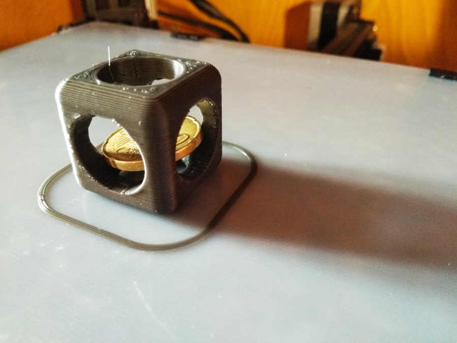
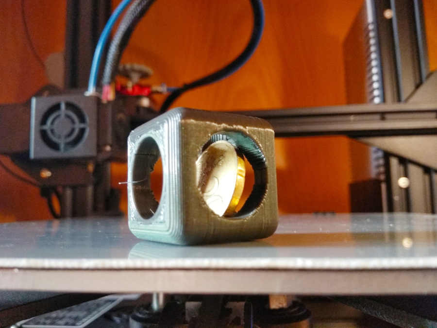
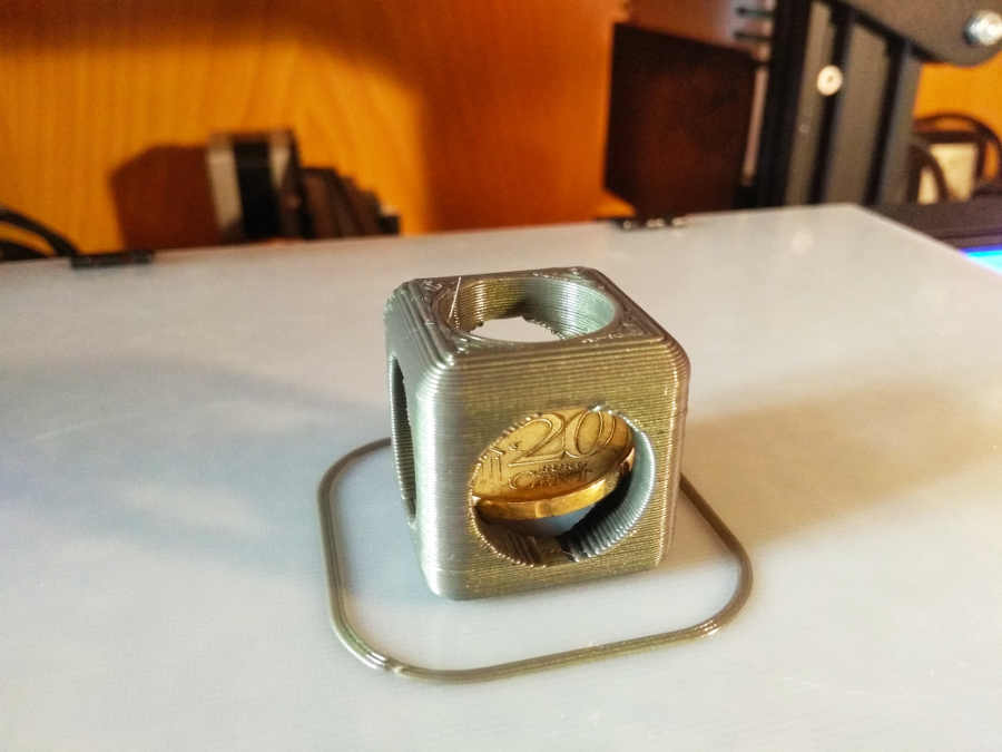
Here are the .STL files and a clip to see the process from start to finish.
I also wanted to try and make a comparison between a representation and a scan...This is the representation of the object scanned for this week's assignment.
3D scan an object, try to prepare it for printing (and optionally print it)
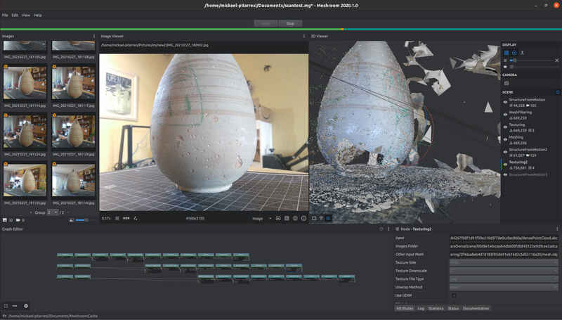
To produce the scan, I used photogrammetry and meshroom to recompose the model from the series of images. I am looking to avoid shiny surfaces and for something with a texture to see how well it is represented in the reconstitution…
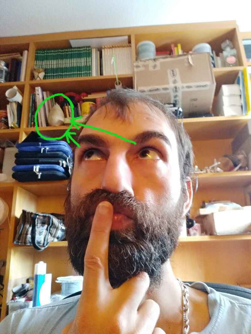
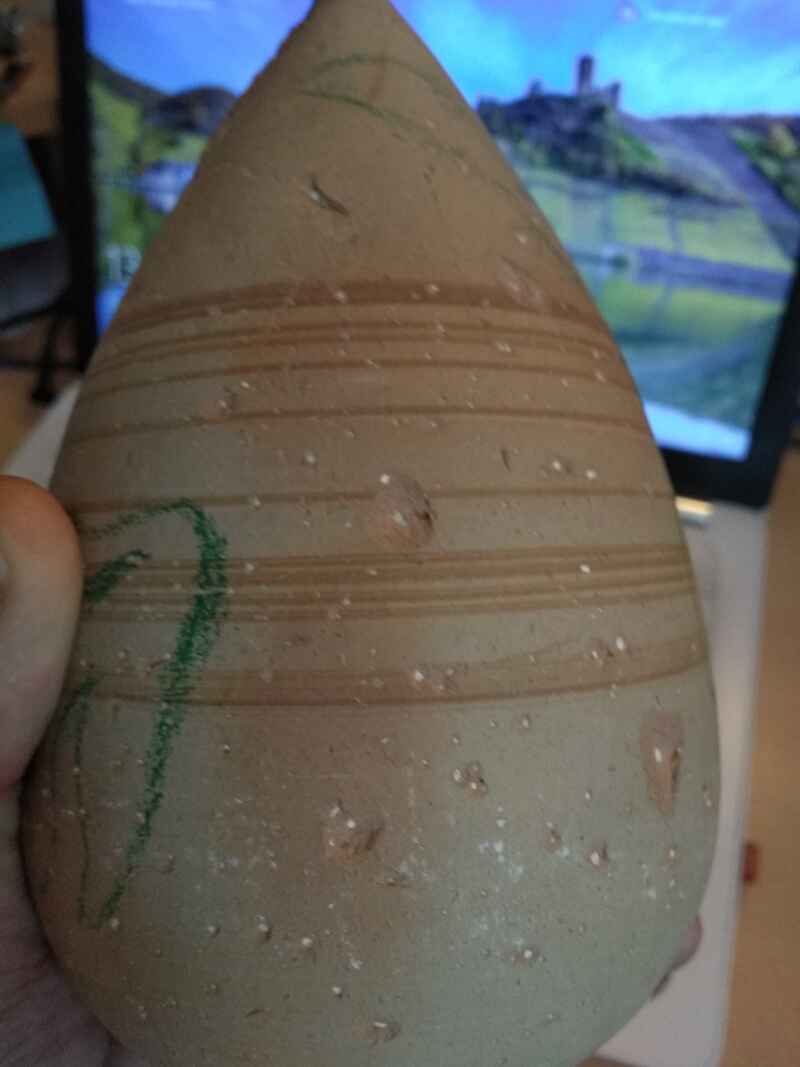
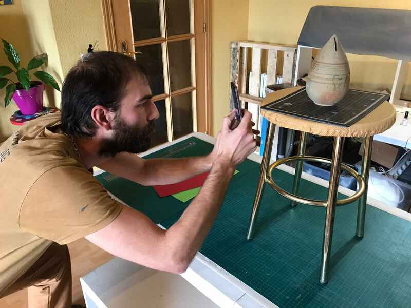
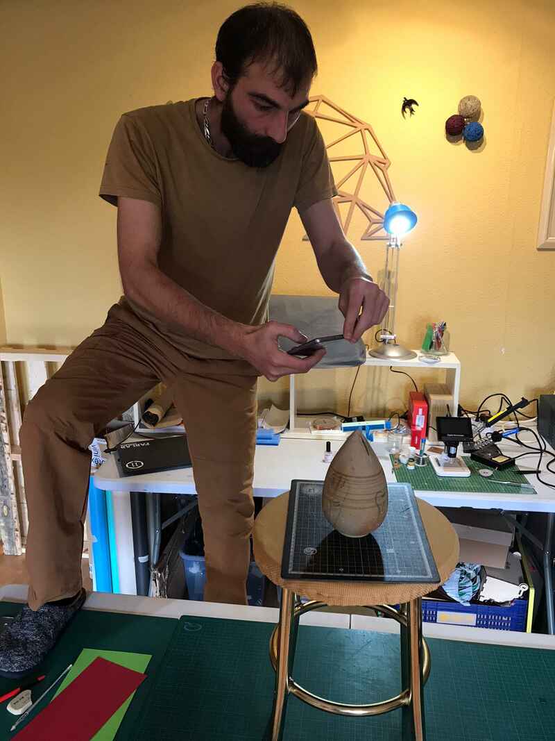
I found this coin jar (it's full, I think none ever got the courage to break it open), it is many years old. For what I was told, it is handmade out of what looks like some kind of clay/pottery, which I think will be the perfect subject for the case. It looks to be about 17 cm tall.
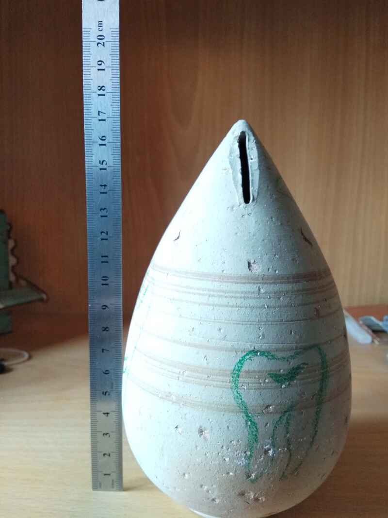
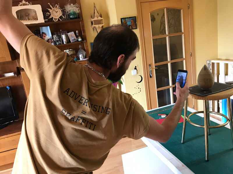
I set it up on a stool on a table, adjusting the lighting in order to avoid harsh shadows (as much as possible). To create contrast between the stool and the object, I set it on a black cutting mat.I followed the suggestions and steps in these tutorials: 1 - 2.
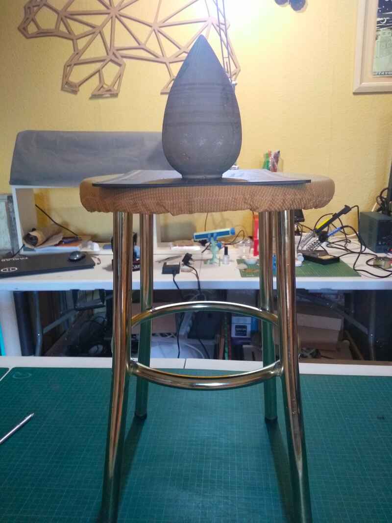
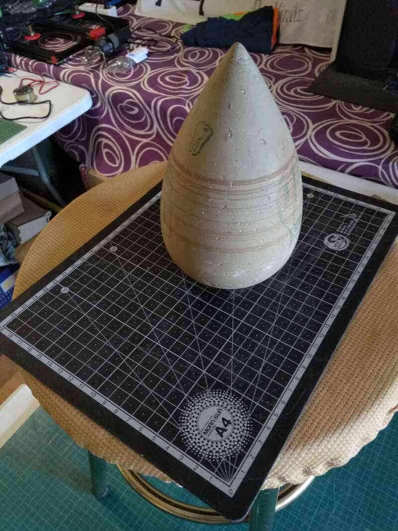
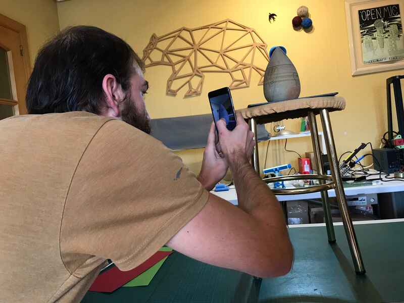
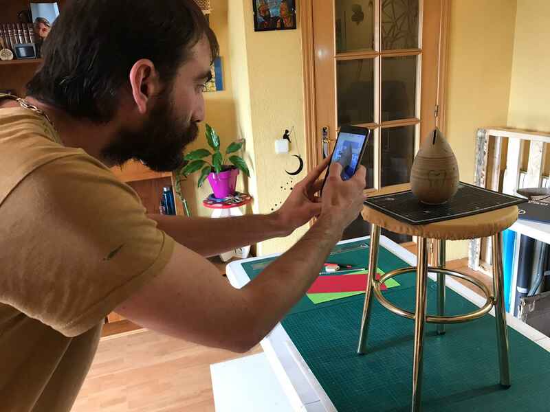
I then took the pictures going in circle around the object...
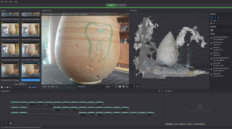
Once the picture taken, they were loaded into Meshroom and the reconstruction started…
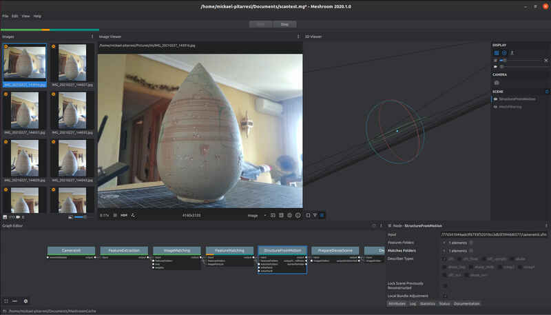
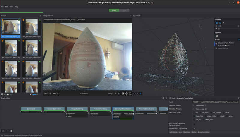
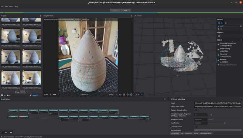
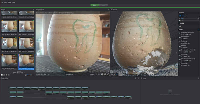
Some very apparent defaults and missing areas, so I went back and took more pictures, added them to the project files and continued the reconstruction process. I took about 100 photos in the first series and added about 40 to 60 every additional time.
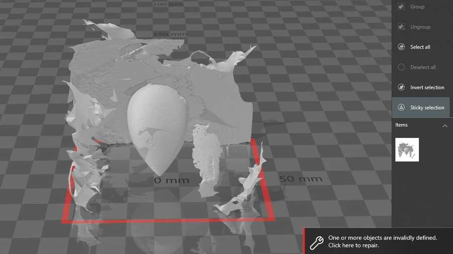
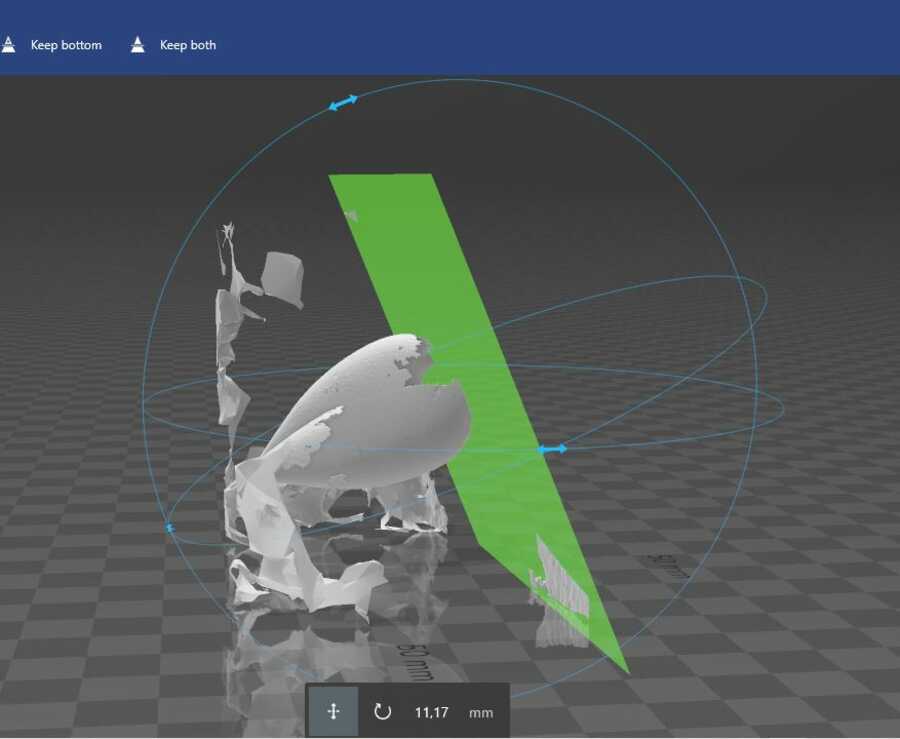
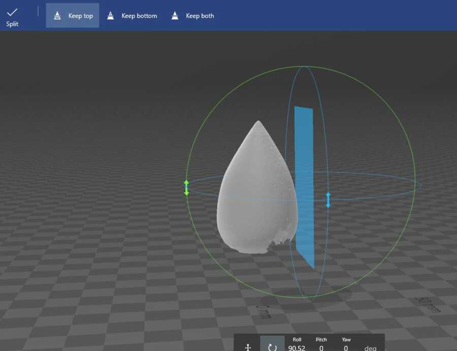
I got the OBJ by opening the folder directly from one of the processes (right click) and opened it in 3d builder for clean up. I used the split tool to remove the unwanted parts.
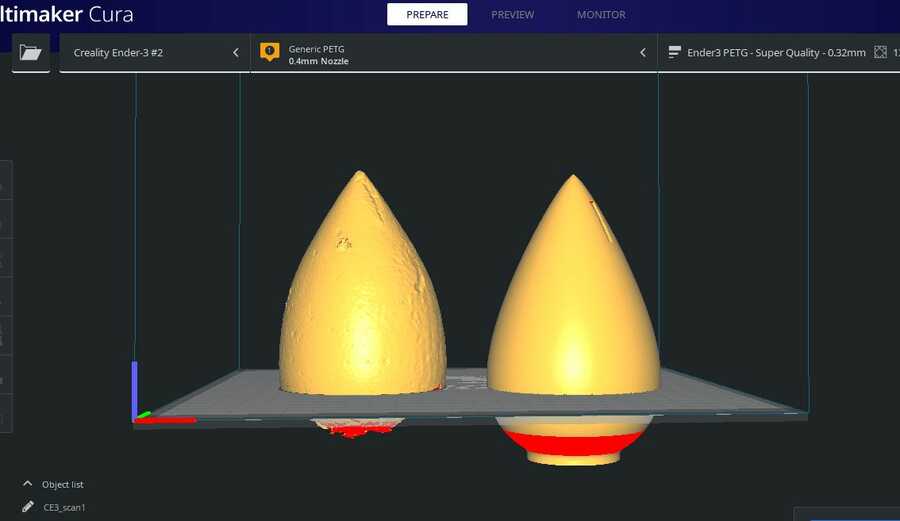
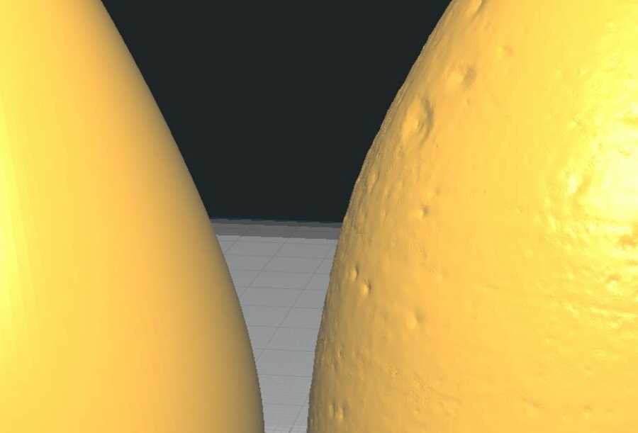
Saved it as an STL and into Cura, the first apparent difference is the size compared to my representation. I could probably have done that in the previous step but I am just going to match the scale now.
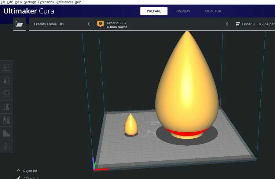
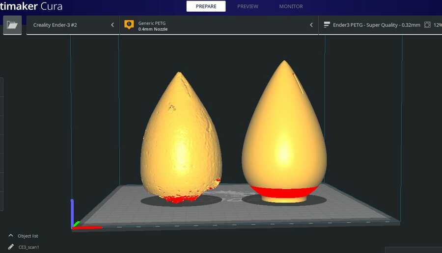
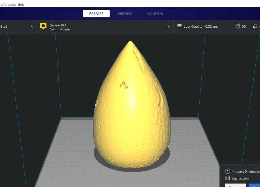
I will be printing the part as it is but I will start the print a little lower to avoid the worst part of the scan and give us a chance of success. A 0.32mm layer height, no infills…I can already tell that the gap where the coins would usually be inserted is closed on the scan but the depths were very well picked up and the texture very similar to the object itself.
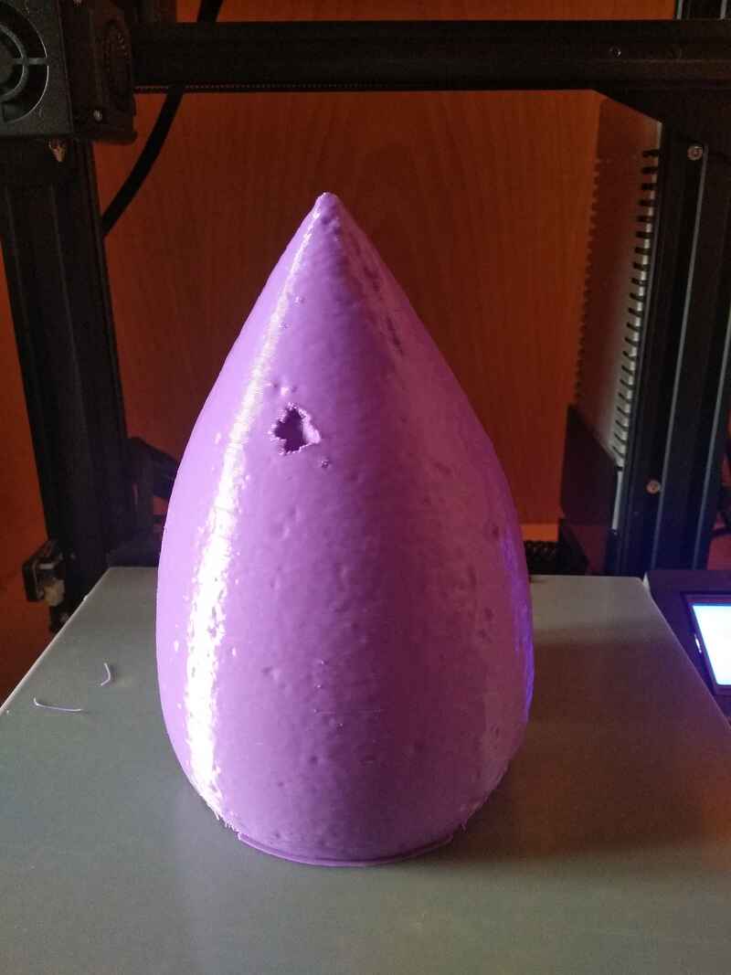
And here is the full size printed version compared to the original.
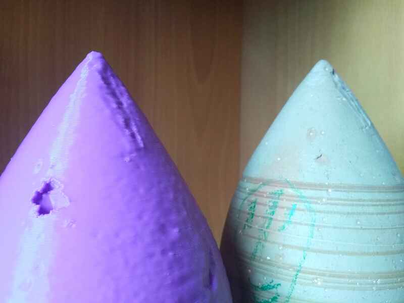
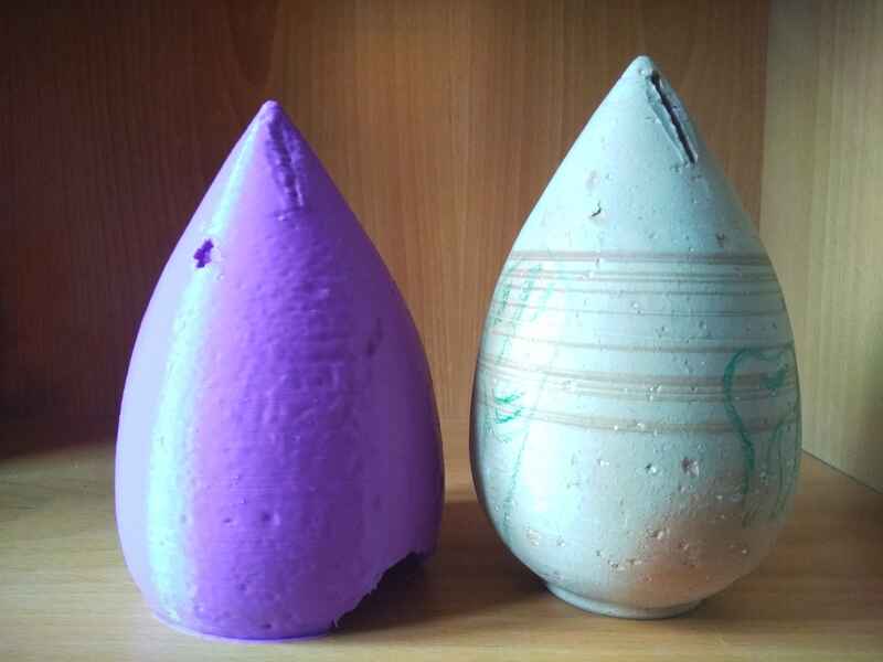
Here you can find the .STL files of the scan and the representation the I designed.
Photogrammetry feels like a very tedious process and the reconstruction work needed on the computer (+cleaning/fixing) can take quite a while... but I feel that with the right lighting, a good camera(DSLR) and stability. As long as the model is not too small, it can be really successful at picking up the details and texture of the object scanned.
Go to:Group assignment Individual assignment
Learning outcomes
Identify the advantages and limitations of 3D printingApply design methods and production processes to show your understanding of 3D printing.Demonstrate how scanning technology can be used to digitize object(s)
Have you?
Linked to the group assignment pageExplained what you learned from testing the 3D printersDocumented how you designed and made your object and explained why it could not be easily made subtractivelyDocumented how you scanned and prepared an object (for 3D printing)Included your original design files for 3D printing (both CAD and common format for 3D printing)Included your hero shots