4. Computer controlled cutting⚓︎
For this third week, we will start with tangible work. We are going to use two computer controlled cutting machines: the vinyl cutter and laser cutter, which are the ones we have here at the Lab, although there are plenty of other cutting techniques like plasma, water or hot wire, each with its utility. The vinyl and laser-cutter are very versatile machines and allow us to create, for example, origami, stickers, flexible copper circuits for electronics, 3d parametric assemblys, bendable 3d shapes (living hinges), mechanisms and many other crazy things that my fablab instructors had shown me examples off, but the are dangerous too. As this is the first bath in terms of using machines in the Lab, I will be especially careful with safety this week. Here are the Assesment Criteria related to this fourth assignment, Computer Controlled Cutting:
-
- Characterize your lasercutter’s focus, power, speed, rate, kerf, and joint clearance.
- Document your work (individually or in group).
-
Individual assignment
- Design, lasercut, and document a parametric press-fit construction kit, which can be assembled in multiple ways. Account for the lasercutter kerf.
- Cut something on the vinylcutter.
-
Learning outcomes
- Demonstrate and describe parametric 2D modelling processes.
- Identify and explain processes involved in using the laser cutter.
- Develop, evaluate and construct the parametric construction kit
- Identify and explain processes involved in using the vinyl cutter.
-
Have you?
- Linked to the group assignment page
- Explained how you parametrically designed your files
- Documented how you made your press-fit kit
- Documented how you made your vinyl cutting
- Included your original design files
- Included your hero shots
Laser cutter⚓︎
The first machine we are going to work with is the laser cutter. In the past I have worked with other laser cutting machines but my interaction with them has been more like a means than an end in itself. I used them to build models during some architecture courses, and the use was guided by a person, although with time, experience and knowing the few values that the cutter handled, I used them on my own.
Although I have already handled similar machines before, the first thing we should do is find out about the model that we are going to use and check the security measures it has, both the machine and the space in which we are going to work.
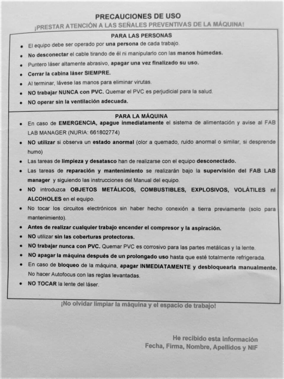
Safety⚓︎
The first thing that my instructor Nuria has taught me in the use of this machine has been the precautions for use. Also Neil was also quite insistent in this aspect during the global class, due to some accidents that his students had in the pastAfter she explained them to me thoroughly, I have signed the paper as confirmation of having done so and being prepared for its use. (I have included a translation for those non spanish readers)

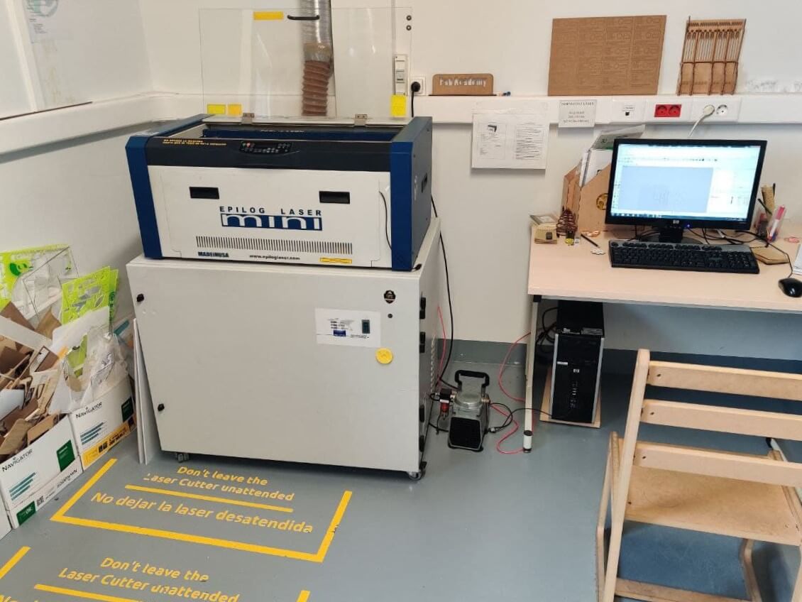
The space⚓︎
Fab Lab Leon has a dedicated room for the laser cutter. You can make a virtual visit to the space to know it personally. The machine has a dedicated computer to work with it, and there are the relevant safety signs posted around the room.

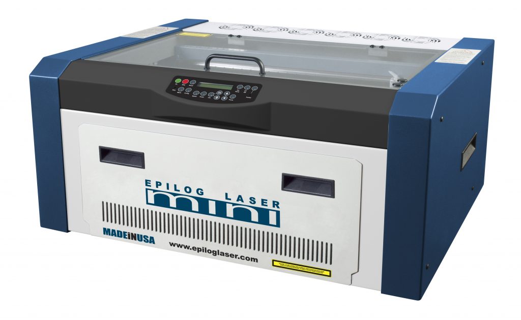
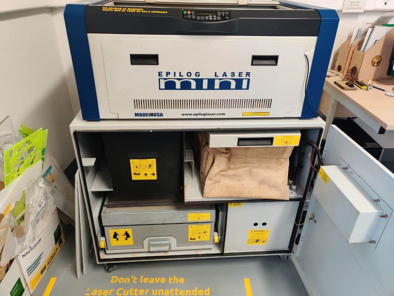
The machine⚓︎
This are the specs of the machine we are rocking here:
- Model: CO2 Epilog Mini 24
- Power: 40W
- Working area: 610 x 305 mm
- Maximum working height: 139.7 mm, 203 mm without plate and grid
- Temporary memory: 64 MB
- Maximum working temperature: 32 degrees
- Software: Rhinoceros + Driver of Epilog
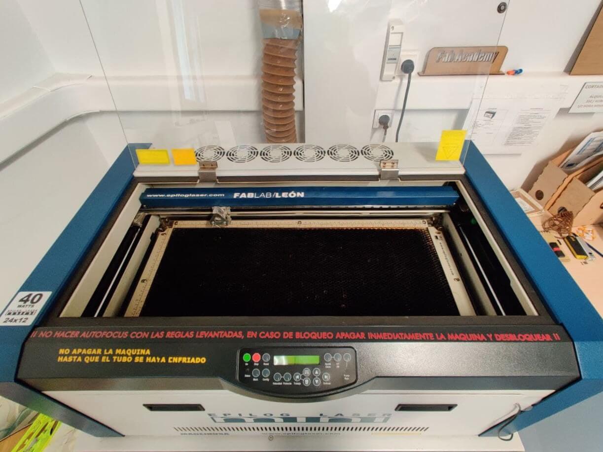
Ventilation⚓︎
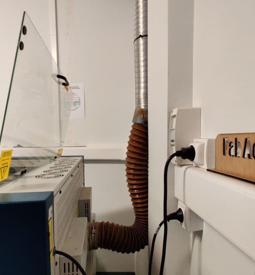
A key aspect of a laser cutter is the extraction system it has. At the end of the day, laser cutting consists of burning a material very precisely, so it is important to extract the smoke and substances that are released when cutting with the machine, because they can be harmful to our health and shorten the lifespan of the cutter if not managed correctly.
In this case the laser cutter has two extraction systems. Currently it uses a pump that collects and expels the air to the outside through a ventilation pipe, as can be seen in the first photo below. Previously it used a filter system, since the machine was not near an access to the outside. This system is still used when the machine is moved to expose it in the main space of the fablab, but it is very noisy.
Software⚓︎
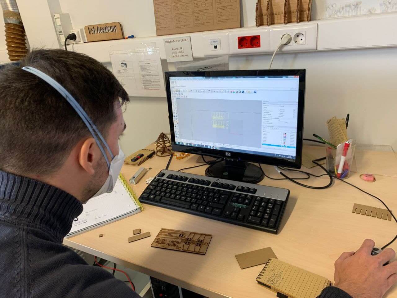
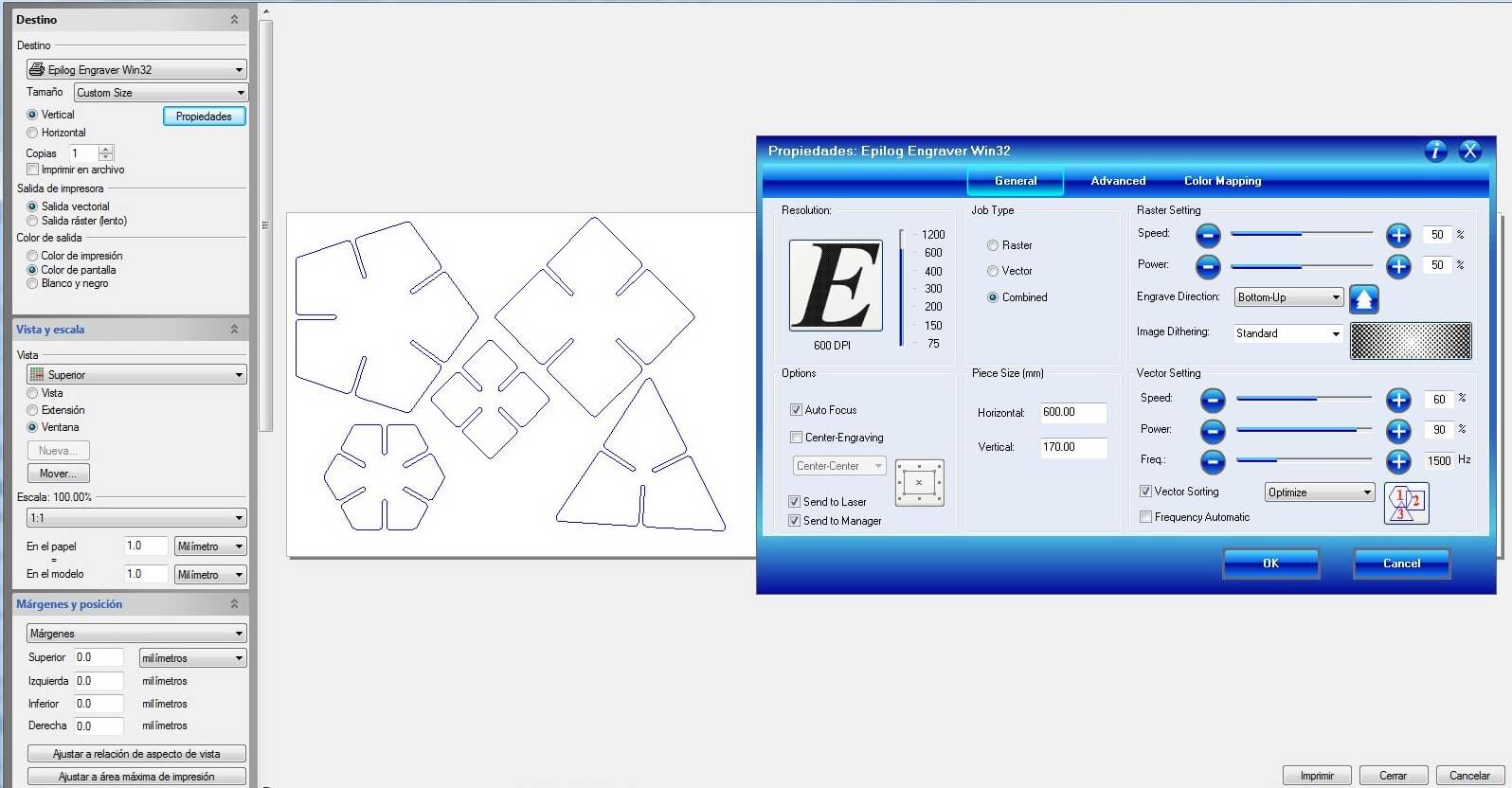
Now that we know the machine, we must learn to use the software to be able to operate it. The laser cutters that I had previously handled used specific laser cutting software in which you only entered your “.dxf” file, configured the cutting parameters and sent the work to the machine.
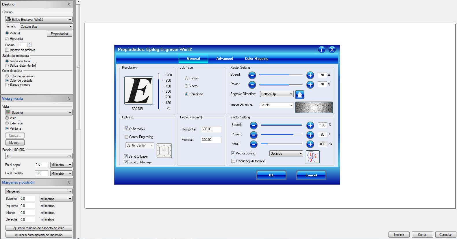
In this case, the computer connected to the machine uses Rhino 4 to be able to read the cut file (preferably Rhino 4 “.3dm” althought most vectorial files are compatible). Once in the program, through the print option, we must select the laser cutter. Once selected, by clicking on the properties button located below the selection, the Epilog driver opens revealing all the configurations and parameter settings that can be configured.
I want to detail this proccess very precisely for when I have to use the machine again during FabAcademy and don’t remeber some settings, so I don’t bother my instructors with something they already taught me.
The first important parameter that we must indicate to the machine is the total size of the pieces that we are going to cut. By default, the maximum size of the machine’s tray is predetermined, but it is advisable to follow this step to check whether or not our model fits within the material space that we have. After having determined these data and having configured the rest of the parameters, epilog generates a window in the rhino model space, so in “View and Scale” we must select “Move”, zoom out of the model because normally it generates it very far away, select the peak of the epilog window and move it to the rectangle of our model that defines the dimensions of our material.
This option allows us to specify to the machine if we are going to perform cutting, engraving or both. In Rhino’s printing options it also offers us this option, but in this case the raster option will only be used for photographs. For everything else we will use “Vector” in Rhino printing settings and “Combined” in Epilog software.
Tip
A trick that Nuria gave me, is to modify the engraving direction, from “Top-Down” to “Bottom-up”, because the extractor sucks the air through the upper part and when recording the material , the smoke that gives off is extracted without passing through the already recorded area, dirtying the result.
This is a utility in the epilog software that allows you to set different parameters for each color assigned in the design. FabLab collegues use this tool alongside Rhino’s “layer color” to stablish a code for the machine to operate. This also allows file compatibility between colleagues, and in case it’s someone else who performs the cutting task, will know what type of cut corresponds to each part of the model.
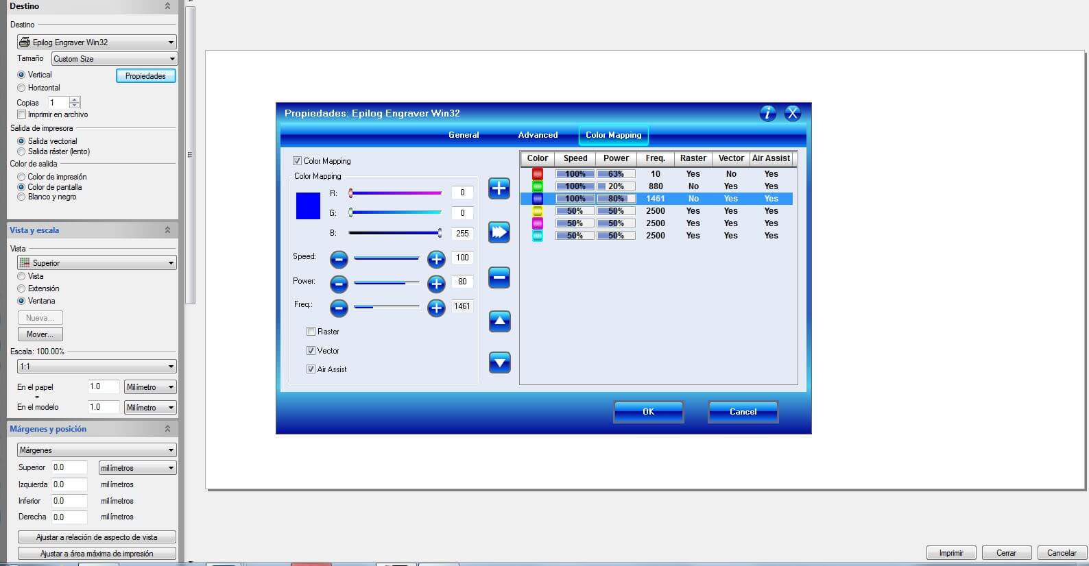
It is also necessary to specify the print width of each layer of the rhino model. The laser cutter is configured in such a way that a line with a thickness less than 0.01mm, which is specified as a “fine line” in Rhino, is only interpreted as a vector and one greater than 0.25mm as a raster. This is the resume of the code used in the FabLab cutting files:
| Layers | Color | Printing width |
|---|---|---|
| Material | Black | No print |
| Cut | Blue | Fine line(<0.01mm) |
| Mark | Green | Fine line(<0.01mm) |
| Engrave | Red | 0.25mm |
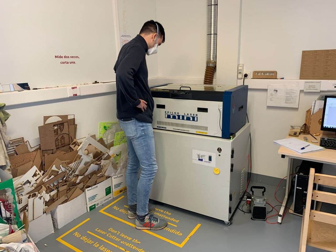
Machine operation⚓︎
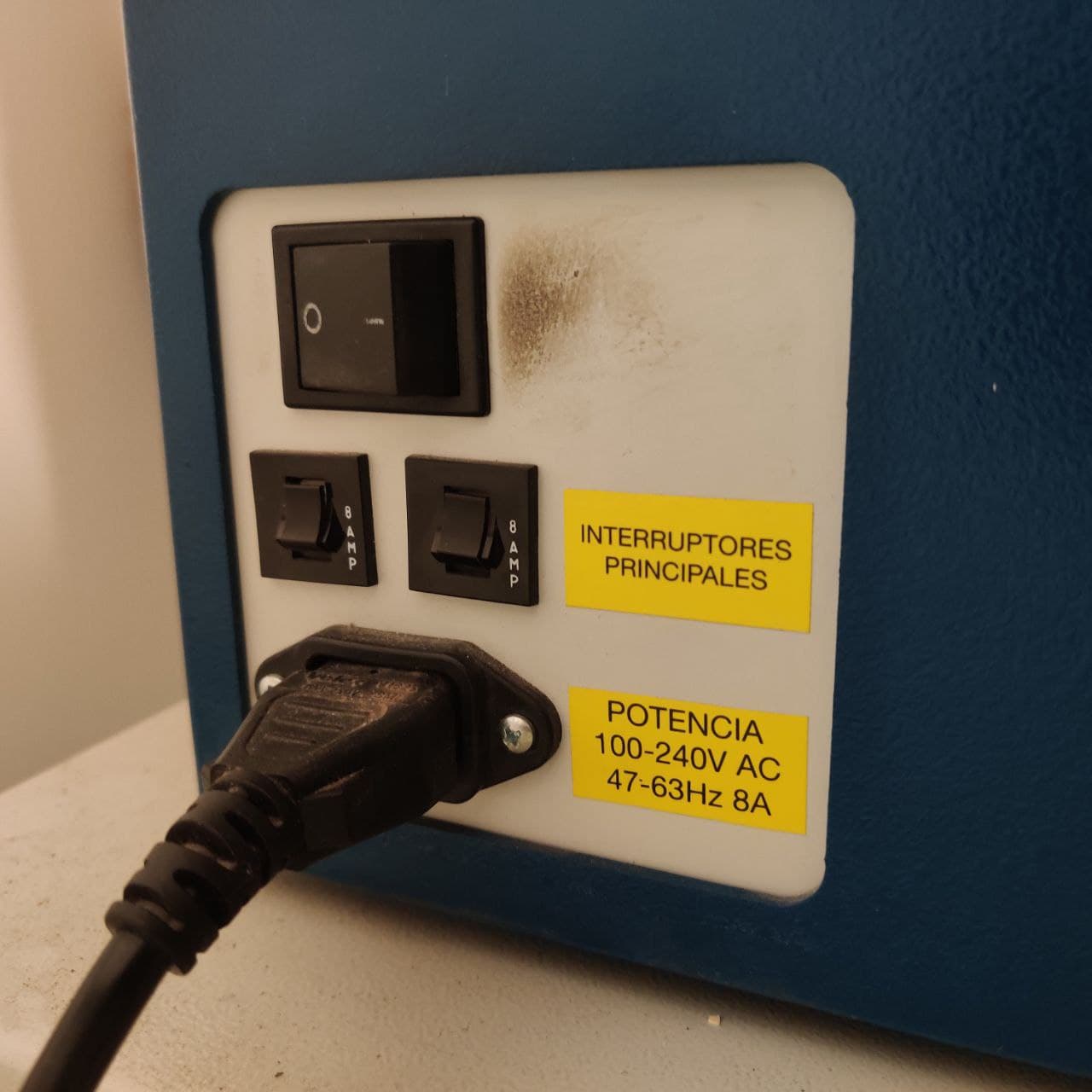
To turn on the machine we must press a I/O switch located at the bottom left of the left panel. We must verify that when turning it on, so do the laser cooling fans. They are pretty loud so we would should notice quicky if they haven’t turned on, but it’s pretty important because if not, the laser CO2 tube will overheat an break.
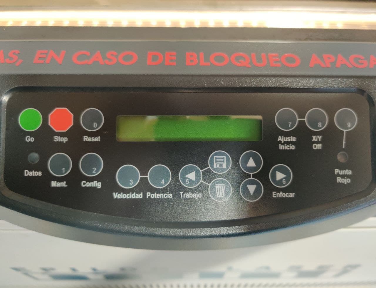

With the machine already turned on and our file ready, we send the file through “print”. This step sometimes get’s a bit buggy so if we don’t see the file name in the screen of the laser cutter, we just have to unplug and replug the usb data cable. Then for managing the cut and the menus, here are some options:
-
Cutting a file: press Reset as a first step mantra to make sure the head returns to the origin. Then we should check the red dot pointer. If it isn’t in the starting position that we want the laser cutter to cut from, then go for the “Setting 0 offset” step. If it’s correct, we have to turn on the extraction system with the switch located in the wall, and press Go. It should start cutting. Watch closely.
-
Setting 0 offset: if the red dot isn’t in the desired place, we can move it with the following button sequence. X/Y off > Go > Move the axes to place the red dot where desired > Ajuste inicio.
Group assignment⚓︎
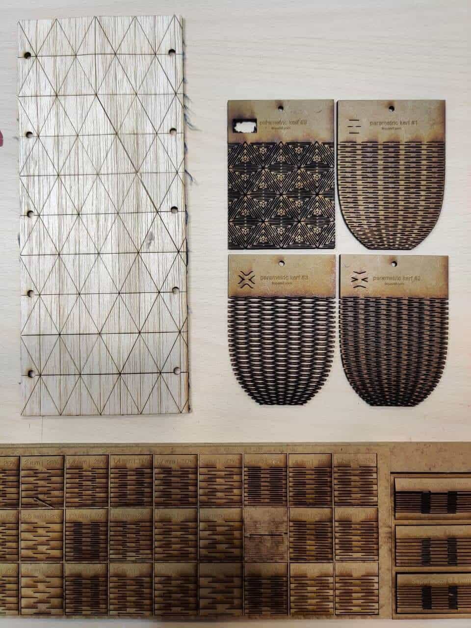
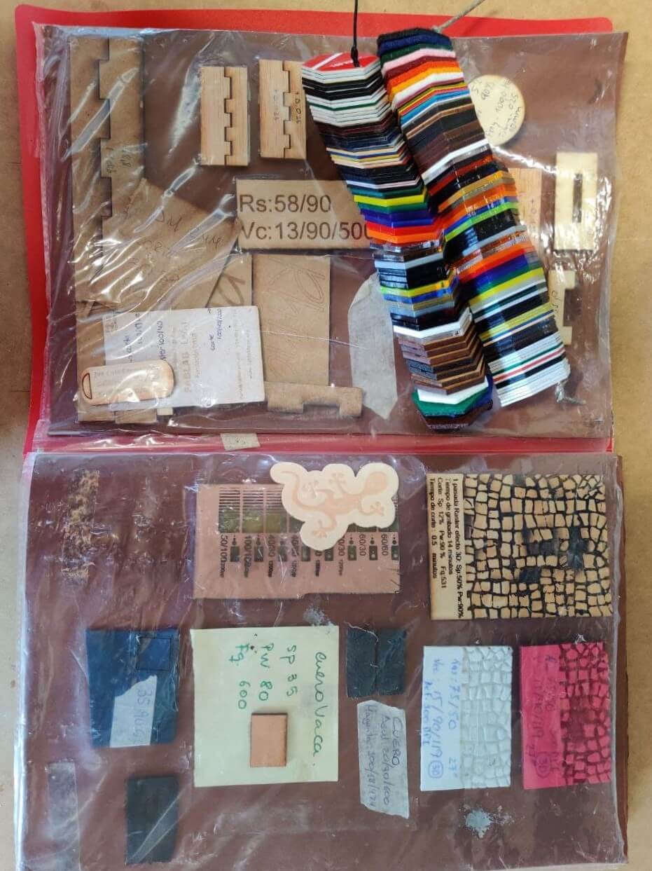
Since FabLab Leon is a site with lots of experience, the laser cutter has been characterized for many types of materials, having a sample of all of them and the values used for each one. Therefore I have to find one that has not been previously characterized and also works for the pressfit kit.
The material⚓︎
For the laser cutter characterization, Nuria recommended me to use cardboard, because it is a lightweight material but resistant enough for the pressfit kit. Although you may haven’t thought about it, cardboard is an essential material in our day to day. It allows us to pack and send packages all over the world (yes, also the one from Amazon to your home), the use of great inventions such as the tetrabrick and even shapes the much sought after product of this pandemic, the toilet paper roll. The question is, what would we do without cardboard?

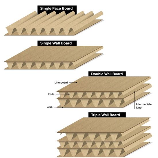
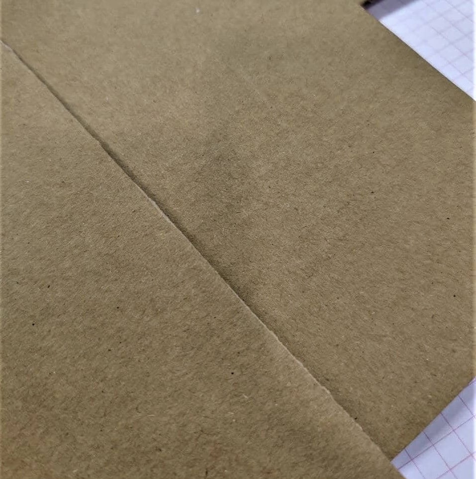
Jokes aside, although it’s a pretty common material, there are many different types of cardboard and it can be a somewhat complex material.
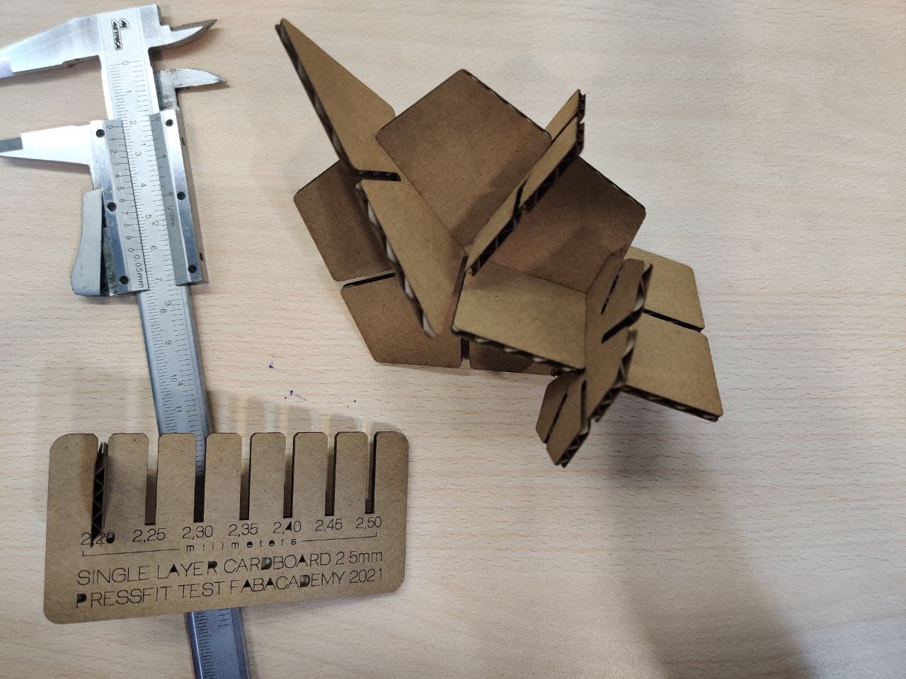
Also, aparently there is “good” and “bad” cardboard, and the difference lays in it’s stiffness, that can be visually apreciated by the corrugations on the surface. As you can see in the photo, here at the lab we have good quality explicitly bought cardboard and the one from an Amazon box. I have to I decided to go for 2.5mm single layer cardboard as I think is the most versatile option.
Characterization⚓︎
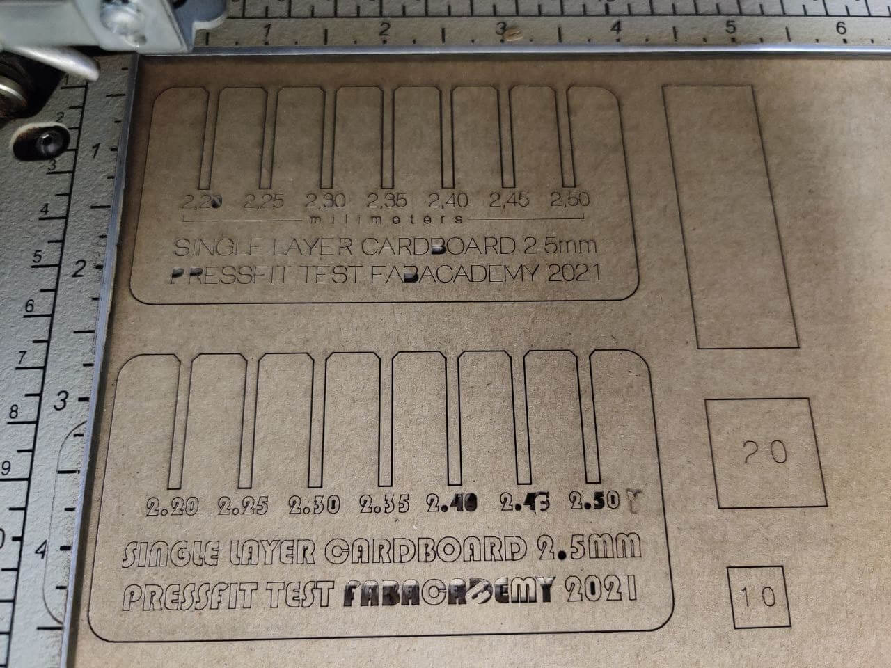
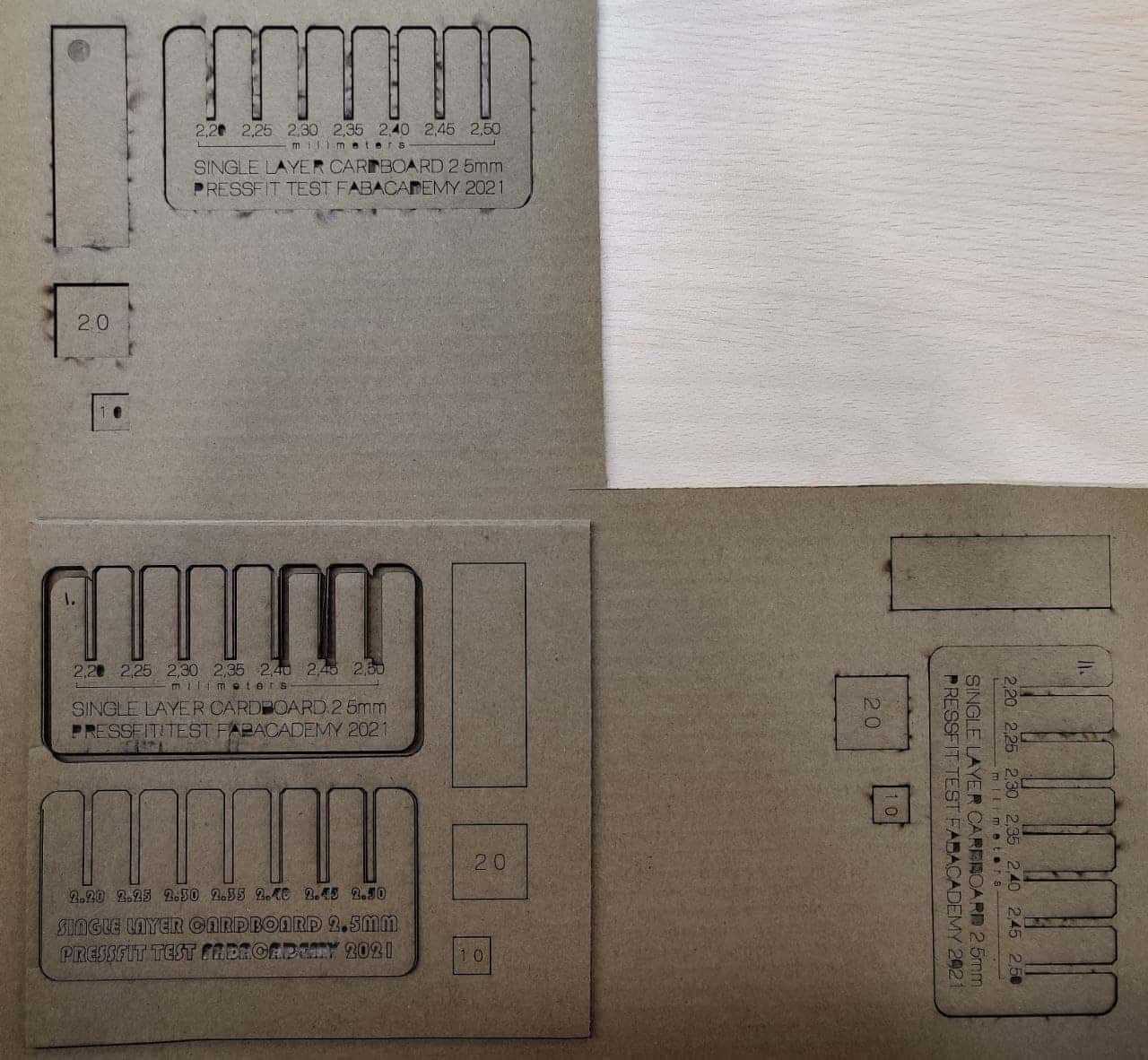
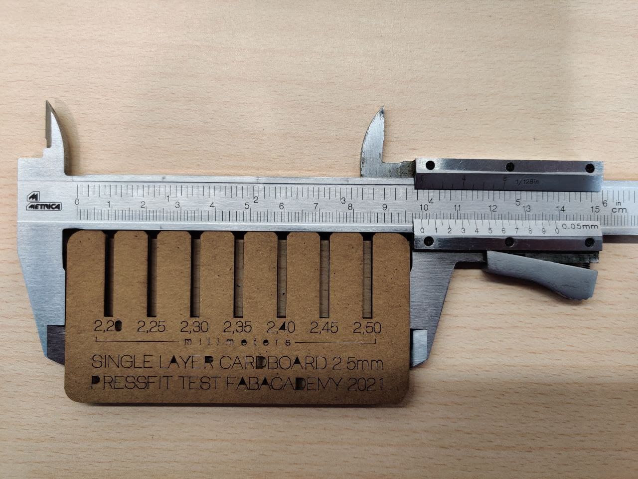
To characterize the material, first we are going to design a comb-shaped element. We are also going to take advantage of the design to calculate the kerf with the meassured 10 and 20 mm squares and check what level of adjustment we want for our pressfit, that’s why we have made this cuts with diferent widths.
Tip
An important tip for working with text on the laser cutter is to try to use a format known as single stroke text. In a first attempt I wanted to use complex text and convert it to vector with the Text Object command, but the result in cardboard and with this font size is quite bad. The single-stroke font used in this case is MecSoft_Font-1. It is important to have it written down, because it has taken me a long time to find one with this characteristic.*
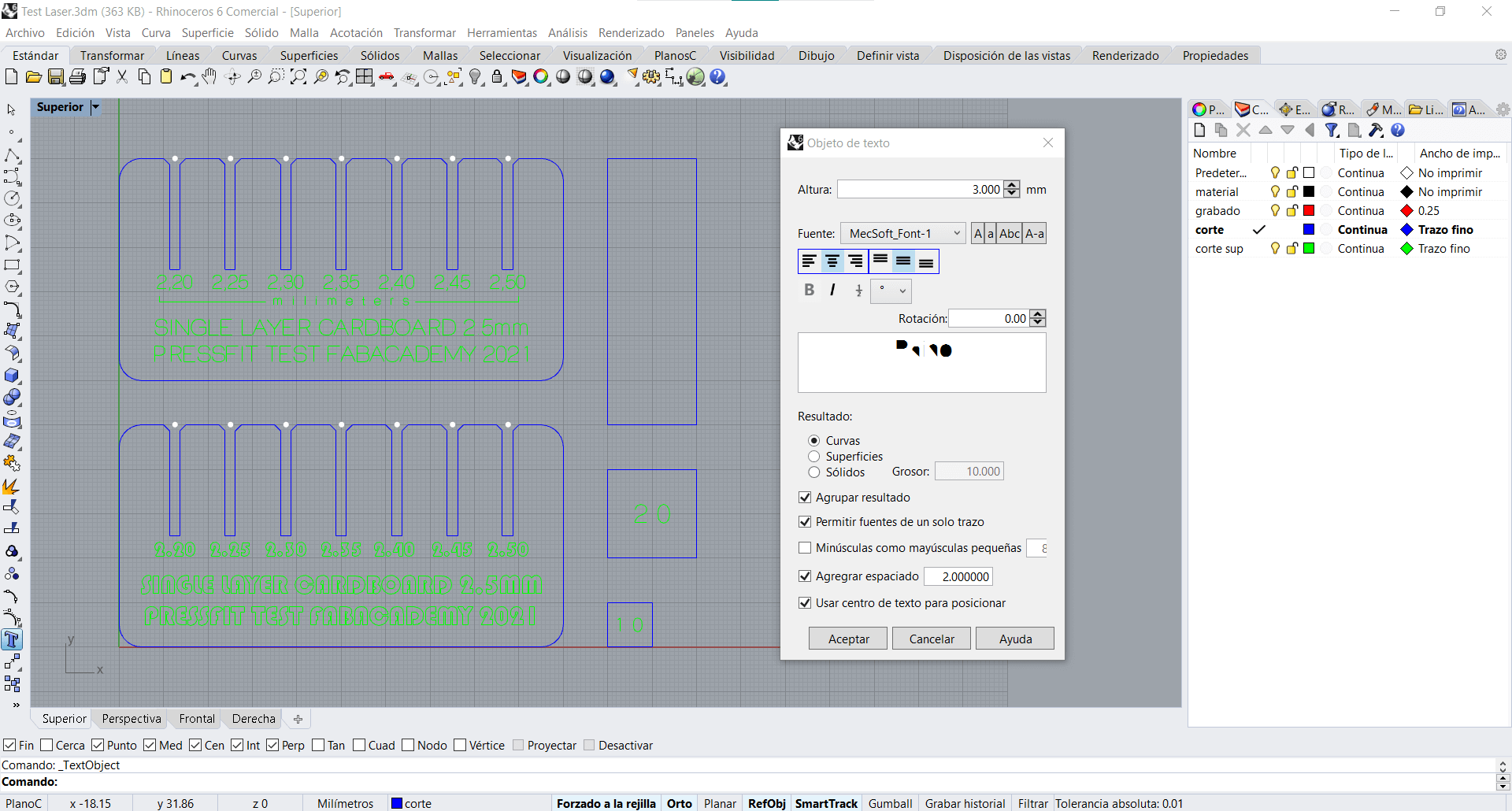
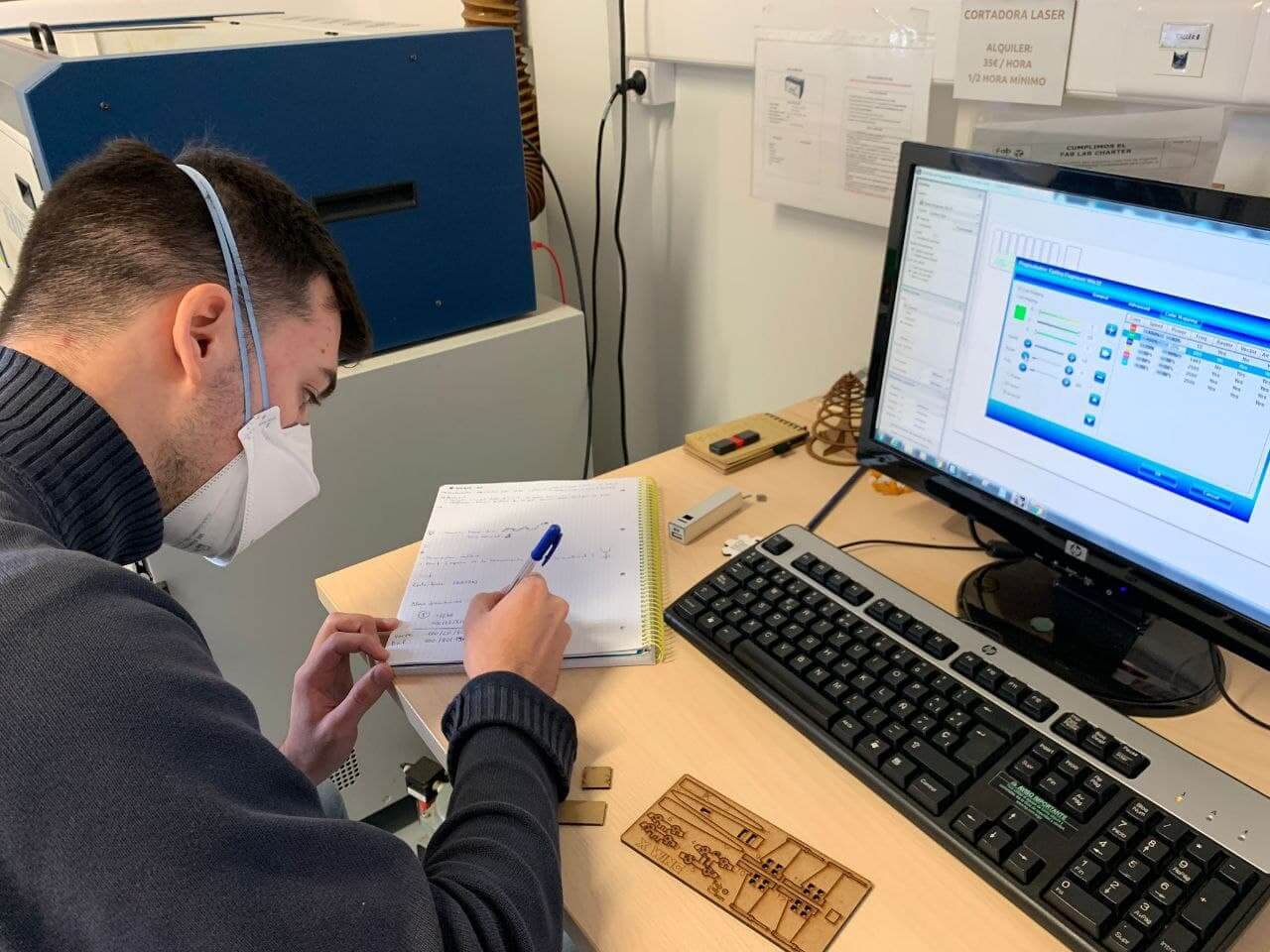
Once we have the design, we use the pc connected to the laser cutter to open the design and follow the process that I have detailed in the software section. Here I am opening and making some adjustments:
For the first cut I have established some approximate values based on some previous work references of my instructor Adrian that he made in his FabAcademy journey. I have decided to set these values lower, because I prefer not cutting the material than burning it. Feels safer.
| FIRST TRY | Speed(%) | Power(%) | Frequency(Hz) |
|---|---|---|---|
| Mark | 100 | 20 | 800 |
| Cut | 100 | 80 | 1500 |
| Engrave | x | x | x |
Placing and adjusting the material for a fresh run with the built in laser cutter rulers, so if we also neither cut trough this time we can repeat the cut without touching the material. I kept watching the machine work closely, as the safety guide says. Also the cutting proccess is kind of hypnotic with it’s precise movements and “drawing” skills.

As I was expecting, the laser didn’t cut trough on the first attempt so I’m going to try to repeat the cut again over the same piece. Trying the re-do option didn’t go as expected, because i missaligned the cardboard checking how deep got the first cut.

It’s time to recalculate and adjust the parameters for a second attempt. I’m keeping written down all the past and new values for the characterization.
I have made a second cut with the new values, but it also didn’t cut all the parts through, just some of them. Even so, the text got finished better. Now, without touching the cardboard, I am going to make a second cut through the same line. These are the parameters I have used for this try:
| SECOND TRY | Speed(%) | Power(%) | Frequency(Hz) |
|---|---|---|---|
| Mark | 100 | 20 | 800 |
| Cut | 70 | 90 | 1500 |
| Engrave | x | x | x |
In this last attempt the cut has worked perfectly. Even a small point that I have decided to engrave on the rectangle has turned out well. It has cut the first time and in a very clean way so these will be my definitive parameters for the cut of my pressfit kit:
| THIRD TRY | Speed(%) | Power(%) | Frequency(Hz) |
|---|---|---|---|
| Mark | 100 | 15 | 800 |
| Cut | 60 | 90 | 1500 |
| Engrave | 100 | 60 | x |
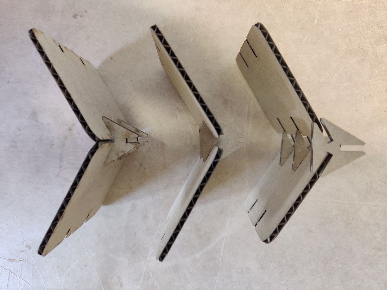
This is a comparison between the three cuts that I have made. At first glance, there is not much difference between the second and third, but the amount of material that the laser has burned is really appreciable when making the second pass in the second cut.
Failure
 While cutting the pressfit kit y decided to tweak the frequency, because Adrian and Mickael told me in the local lab review, it was too high for cardboard, as they cut on this material with frequencies between 400 and 800 Hz.
I lowered it to 1000Hz and the result has been quite messy, as shown, so I decide to go bock to 1500Hz.
Even so, Adrian tried a cut with a frequency of 400Hz and other parameters and obtained a good result, so we have decided that we will investigate more in depth about it these weeks.
Kerf⚓︎
The kerf is defined as the width of material that is removed by a cutting process. Each cutting process removes a different amount of material, or kerf. I have found this article that defines pretty well what Kerf is and all it’s implications when using a computer controlled cutting machine.
In resume, not only does kerf width vary from one process to the next, but there are lots of things that affect the kerf width for each process. Of course, as the thickness of material increases, it takes more power to cut through it. Laser increases power. Regardless of the process, as the plate gets thicker, the kerf gets wider.
It can be calculted making a cut (not to tiny to get less measurement error) and measuring the space left by the material cutted and then meassuring the cutted material itself. This is the formula:
Kerf = (outter cut measurement - inner cut meassurement) / 2
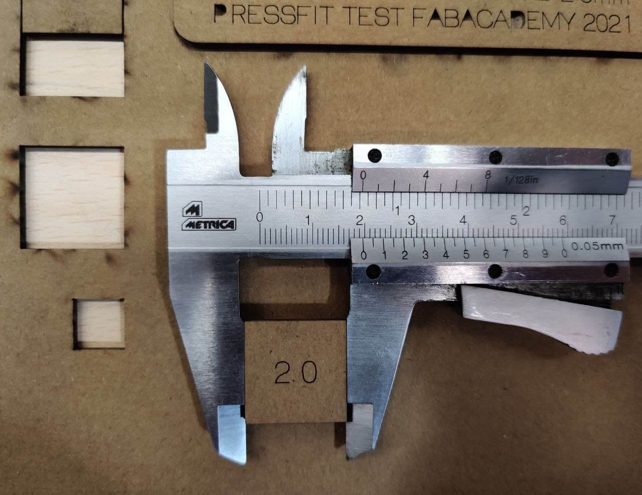
Kerf = (20‘2 - 19‘6) / 2 = 0‘3mm
The kerf value obtained is higher than usual. This may be due to having used a manual caliper to take the measurements, because the results obtained in measurements with such a small range may vary slightly by the observer’s eyes. It can also be due to an incorrect approach by the machine, or excessively aggressive parameters in the cut, but after some checks, that is not our case.
Pressfit kit⚓︎
One of the main points of this week assignment is to design a modular, parametric, pressfit kit using the laser cutter. Pressfit stands for: “The fit of a shaft driven into a hole slightly smaller than itself and held tight and motionless”. As we described in the characterization of the laser cutter for cardboard, our comb-shaped design is going to let us choose how the different widths perform as pressfit and which is the more suitable for the final design.
The pressfit⚓︎
Although the thickness of our material is 2.5mm, the width of the pressfit we have chosen is 2.2mm. This is due in part to the kerf of the machine, so they are not really 2.2mm and the adjustment that allows the corrugated inside layer of the cardboard, which acts as a spring.
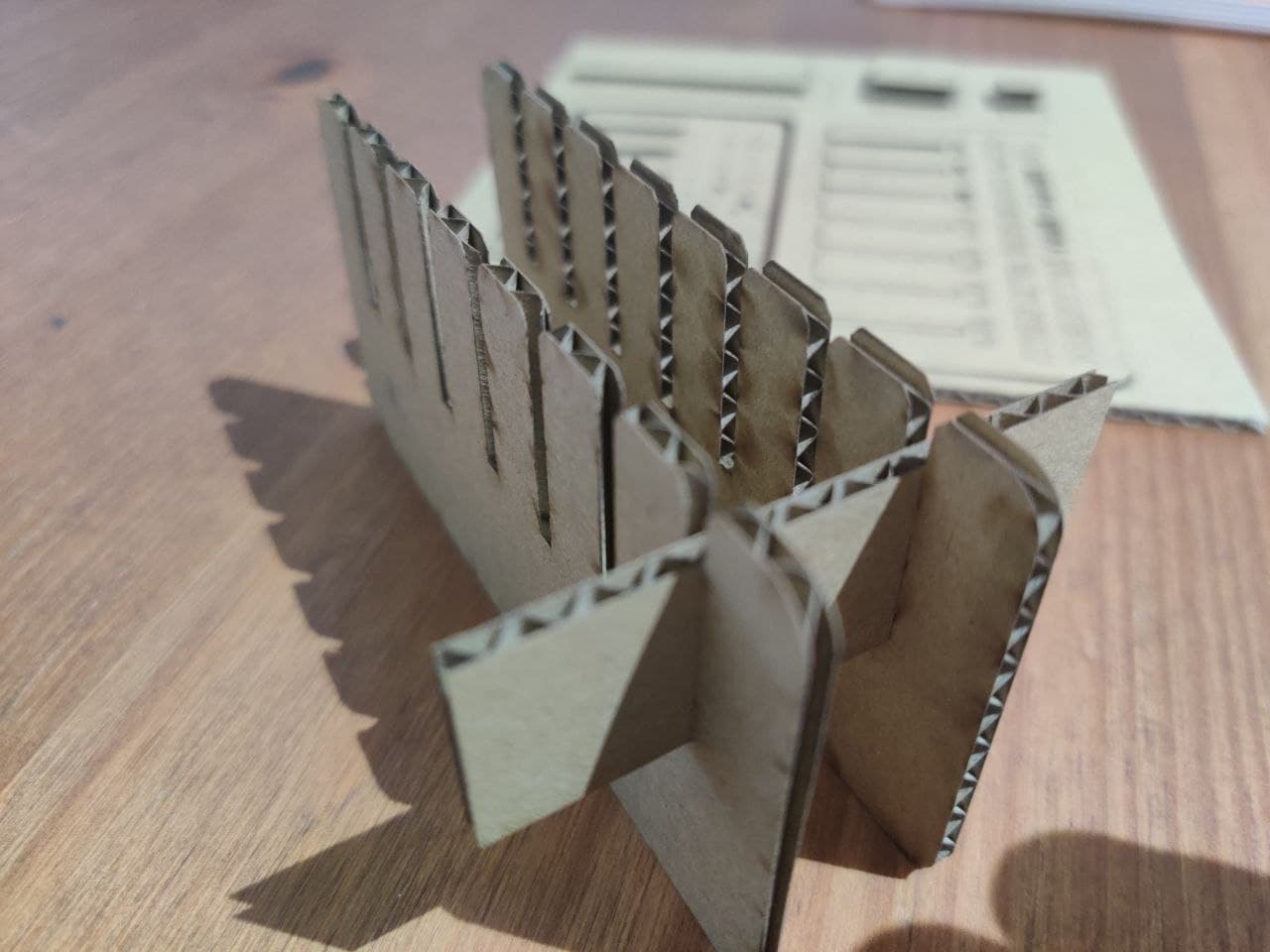
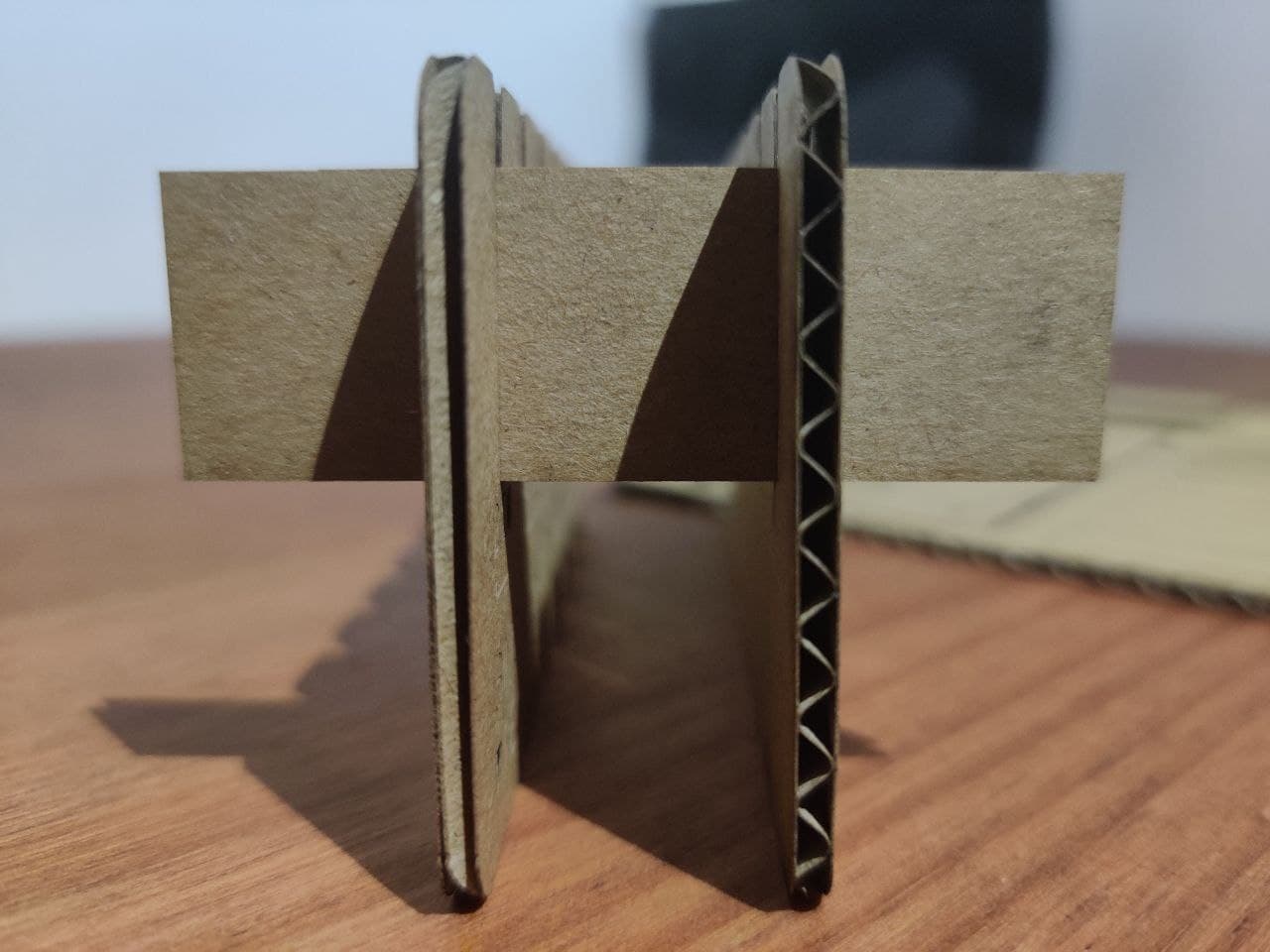
Another key aspect of our pressfit are the mechanical properties of our material. Since cardboard is an anisotropic material, it will behave mechanically differently depending on the direction of the internal corrugation, so it is necessary to find which one is the one that favors the pressfit the most. The ideal position is where we “go through” the undulations of the cardboard with the piece that we insert, so that they exert reverse pressure. In the other direction, the anchor would stay in the existing channels between each corrugation and would be looser.
The idea⚓︎
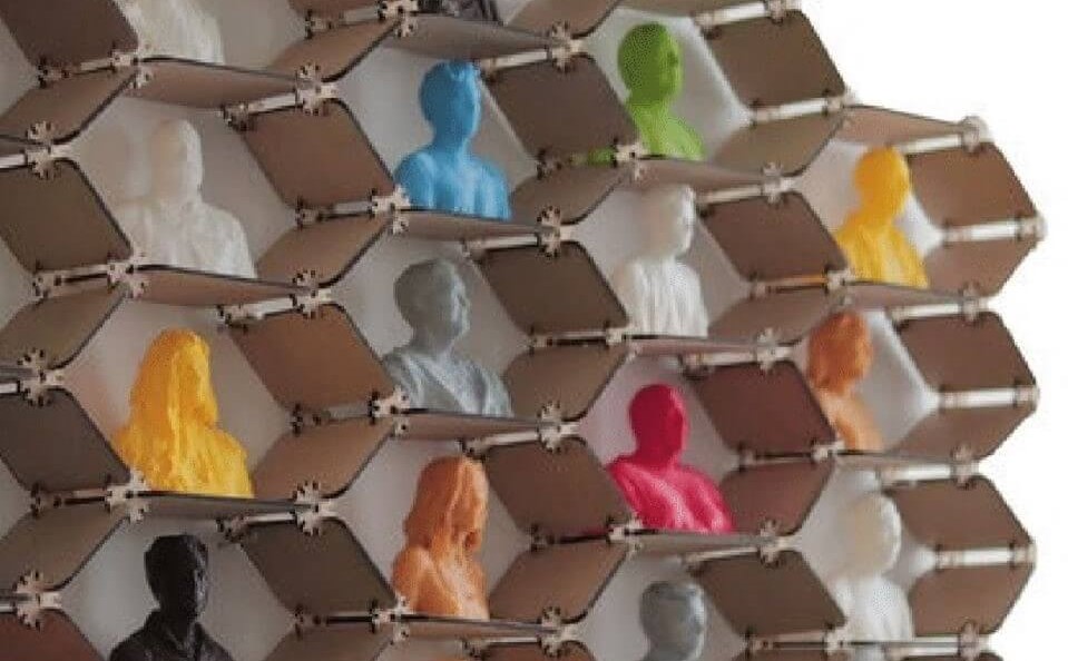
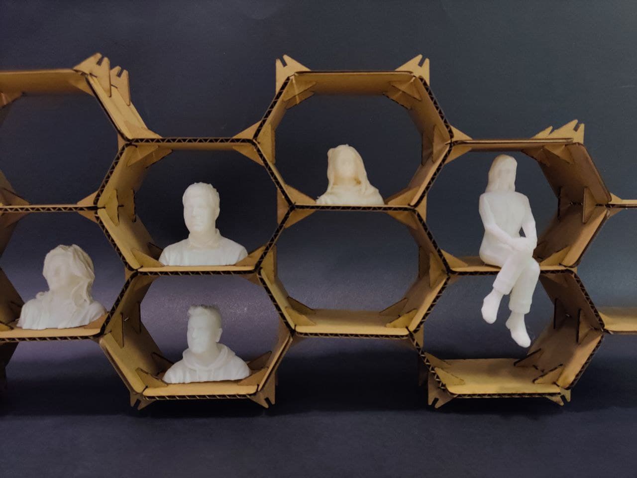
The idea of the design of this parametric kit had been written down from the first week of fabacademy, in which my instructor Nuria commented that they could use a small shelf to place the 3d printed portraits that they had in the fablab. Talking about it, he showed me some designs that he had seen on the internet, so I decided to write down the references for this week. I also decided to experiment with different shapes for the layout in Rhino.
Parametric design⚓︎
My first aproach in the parametric design of the kit has been with the Grasshopper file from Jesus from FabAcademy 2019. I’ve been very curious about Grasshopper for a few years now but I have never used it. Using his already complex configuration is awesome, shapes change with the movement of a slicer.
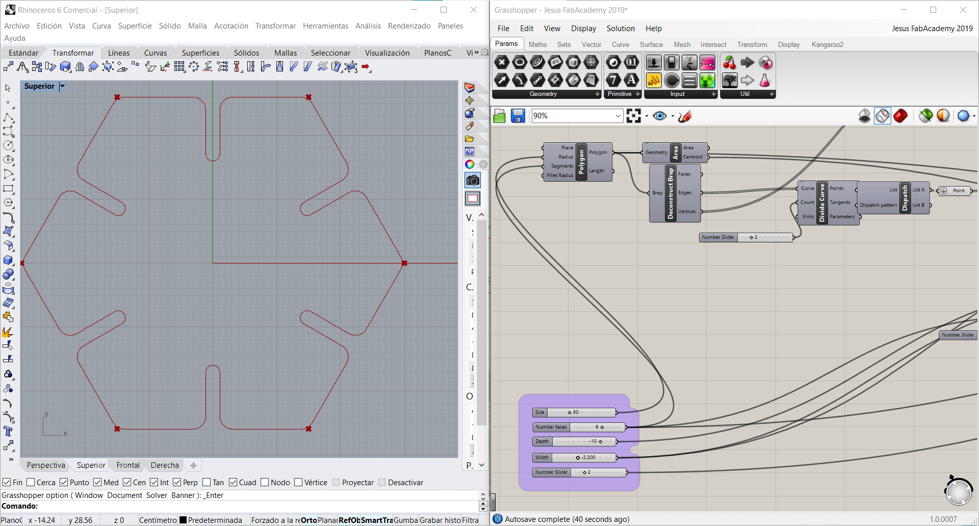
Although it seems an incredible and very powerful tool, it’s too complex for me to be useful in the design of the kit. Anyway I have tried to handle some of the parameters and even change the data type that the slider accepts, from integers to floating (with decimals) to fit my material with the 2.2mm pressfit. Finding out how to take the changing polygon to a normal line in Rhino was also a “fun” experience. You have to “Bake” it! (That’s the actual command)

Now onto Fusion360. Parametric design was incredibly easy with this software. It’s all about making a sketch and making a measure of a specified length, then creating a parameter and determining the length of the measure with the parameter, so that every time we modify the parameter from the parameters tab in fusion, the whole sketch design is redrawed automatically. The problem with this technique is that making a measure is also creating a restriction for the design, so sometimes it collapses because there are too many restrictions that collide. That’s why it took me some time to get used to this tipe of design, but my collegue Mickael pushed me to learn some more skills about this program and he also pushed some design ideas that I thought couldn’t be made in Fusion parametrically and finally did this parametric design.
The problem of working with fusion is that I need to export the design to Rhino every time I want to cut, and it is in this second software where I duplicate and orientate the pieces to cut in the laser, so it only saves me the work of changing the dimensions of the original piece, so it does not rigorously comply with the purpose of the parametric design. Even so, I have been surprised by the versatility of this software and I will try to include it more in my usual workflow. I have prepared a pack of pieces to cut and check how the final shape and fit would be.
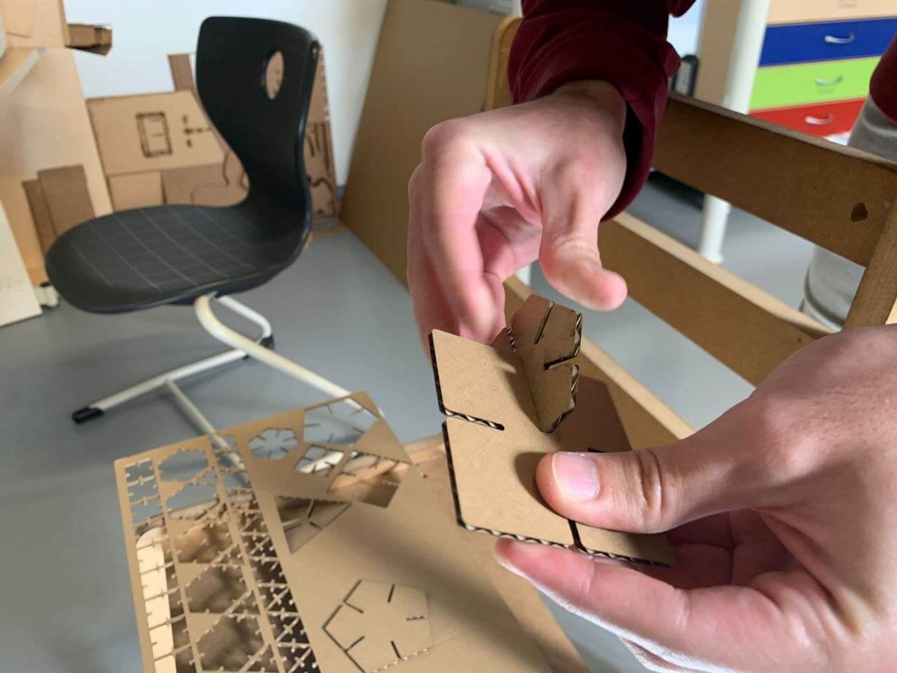
First iterations⚓︎
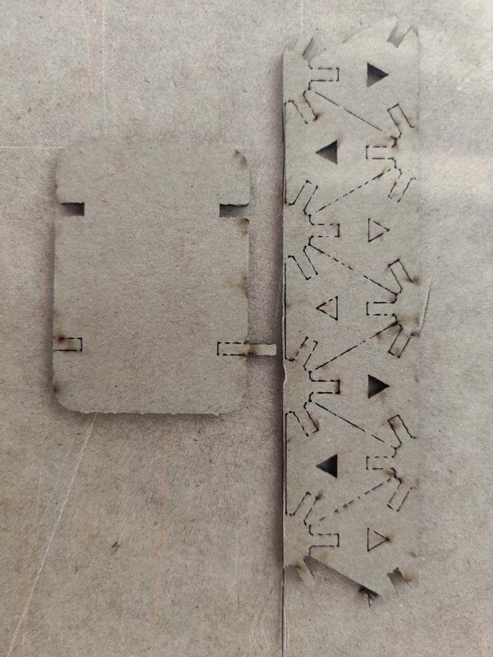
After having made the first design and having cut a module to check the assembly, I have realised that I have not taken into account the overlapping of the fitting pieces in the nodes, so each arm goes inwards not only the depth of the cut, but double the depth because the fitting piece also has the same depth for its anchorage. This means that when trying to fit two pieces into the same node, they both collide.

As can be seen in these photographs, the pieces fit much more inside the anchor than they should because the sum of the cuts has not been taken into account. Even so, as a first iteration to detect errors it has been satisfactory, because assembling the kit without using the anchor holes has also allowed me to see that perhaps the size of the design for the figures for which it is designed is excessively large. Here comes into play the parametric design, having only to modify a couple of parameters to get the same design but with a smaller size, without losing the pressfit adjustments in the piece fits.
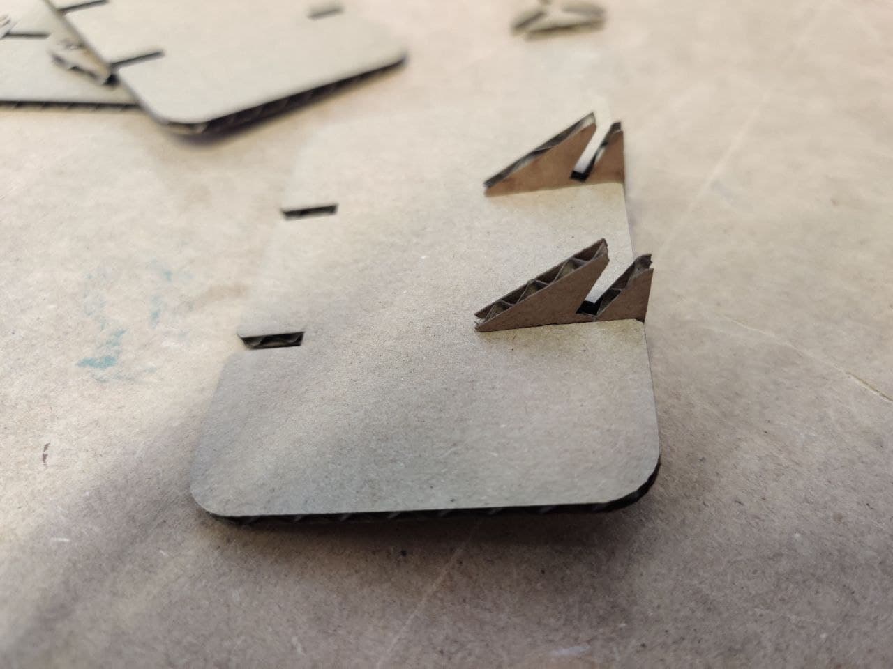
Final design⚓︎
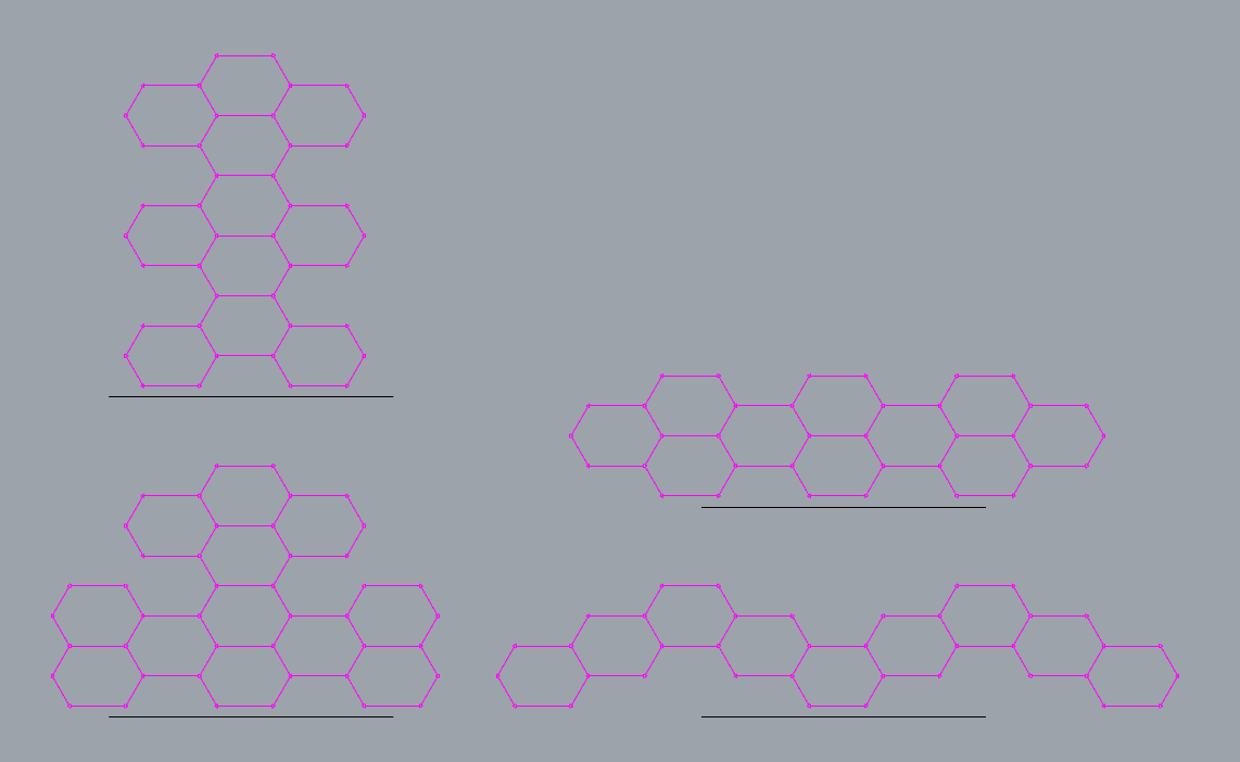
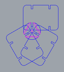
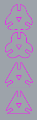
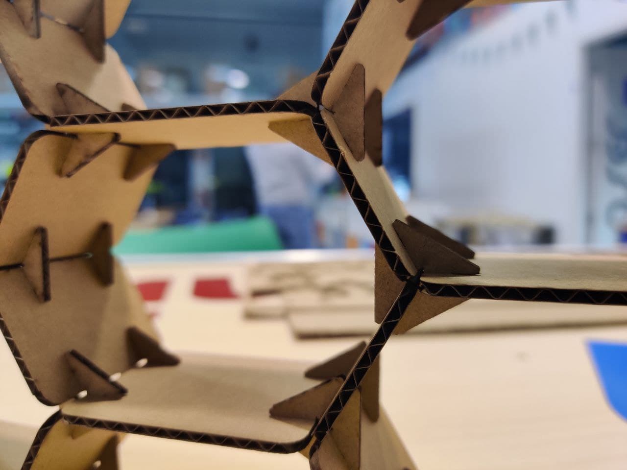
After fixing the problem of the socket depth I spent some time thinking about how I could optimise the nodes, so that with the minimum size they could offer the same strength. Finally the design is going to be straight, but leaving a small edge at the tip so that it doesn’t start from the cutting edge and thus provide that bit of stiffness. Also my colleague Pablo has advised me that to test the depth to which the pieces reach when inserted in the nodes, I could generate the same design in 2D and adjust it to the point that there is only a central triangle between the three pieces that are inserted in the node. I really liked the idea and that’s how I finally designed the last iteration of the nodes.
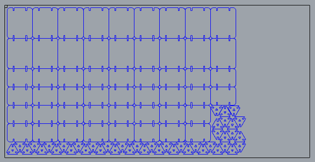
As you can see in the picture on the left, the black line indicates the total size of the laser cutter bed, so one cut should be enough to make all the pieces, although I might make more later to enlarge the structure.
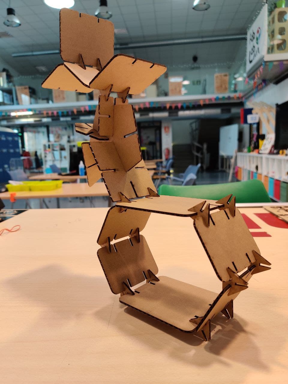
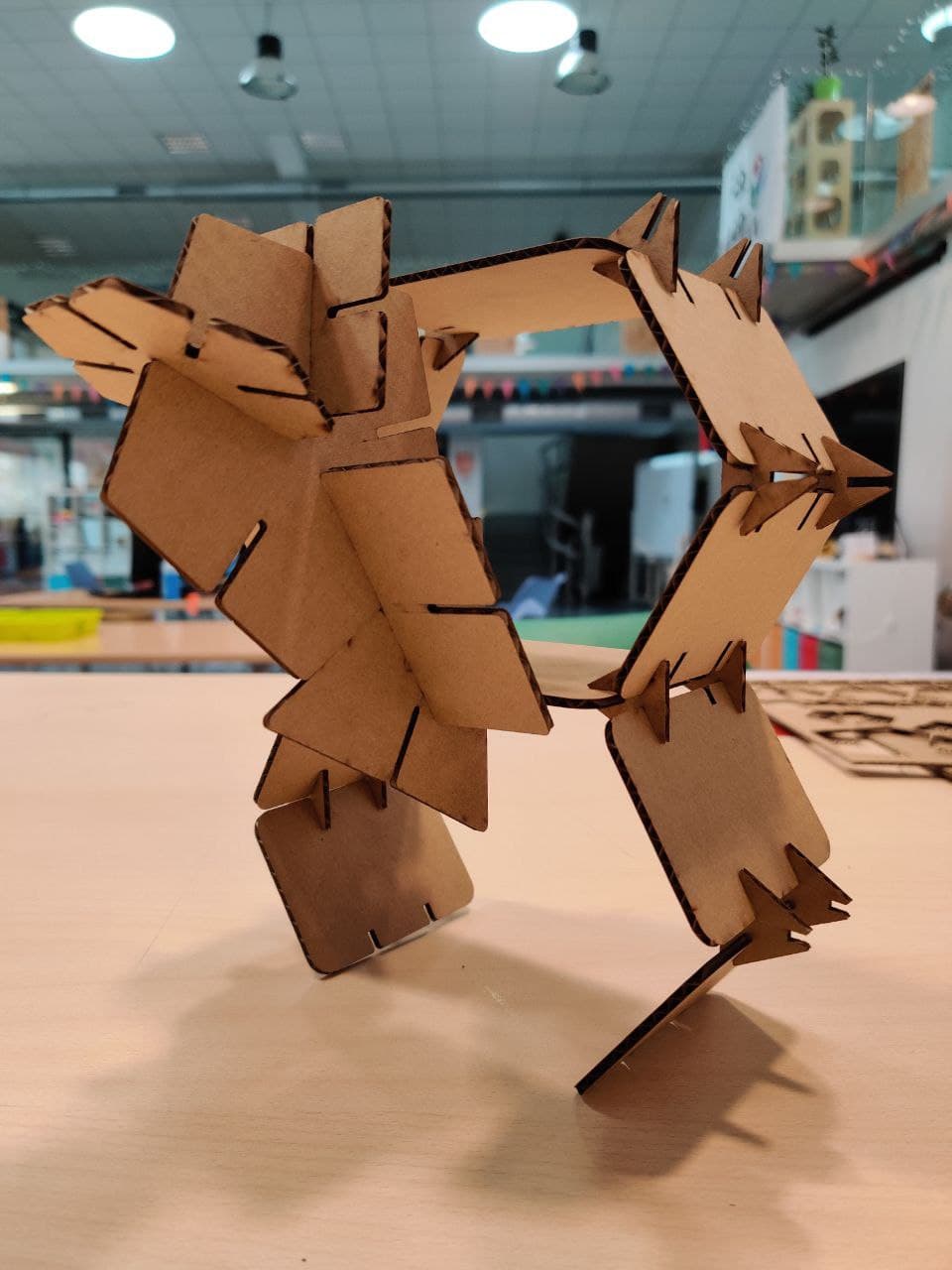
Assembly⚓︎
Before assembling the shelving itself, I have been playing and trying different combinations looking for shapes with the rest of the pieces that I have been cutting during the week as part of the pressfit definition and learning with the laser. These two shapes in particular have been fun for me. The left one reminds me of a fat cat with a furry tail and the right one me recuerda a un cangrejo con un aguijón. Supongo que tendré que buscar el significado de estas asociaciones oniricas. 

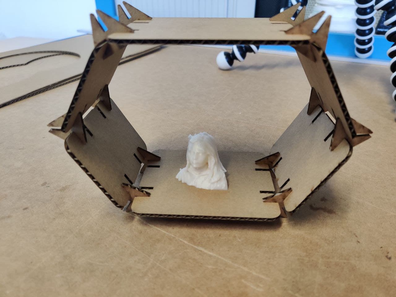
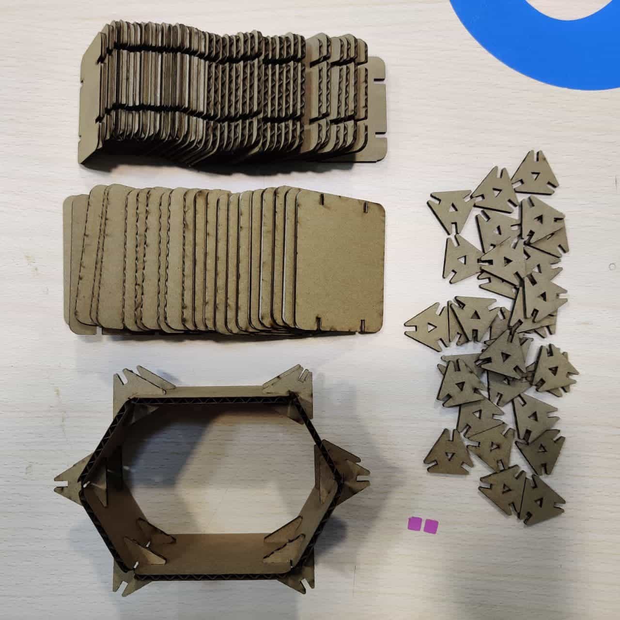
In the picture below is the final pressfit kit to build the shelving. This is for the basic form, as it has not many pieces. I couldn´t cut more at the moment due to a hardware problem with the laser, but later in the morning I would make more pieces to build a bigger version of the kit. I’ll add a video of the assembly process and some final photos later!
This video is a build montage of some parts of the making process and a timelapse of the assembly of the first iteration. At the end of the video you can see another clip where I cutted a lot more pieces and made a bigger version of the shelving.
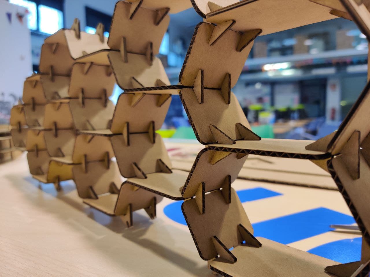
Final shape⚓︎
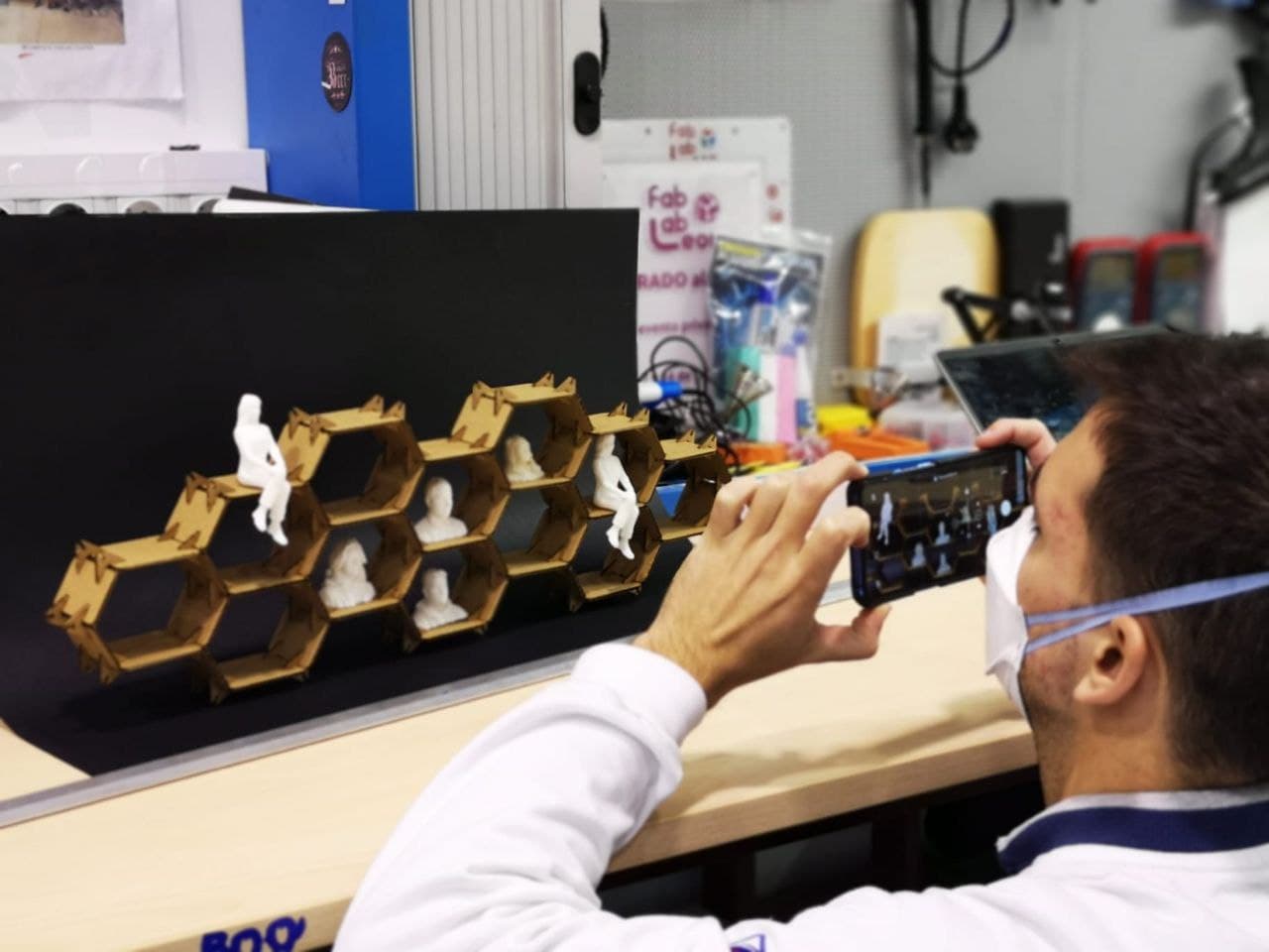
I think the result has been quite nice. The shelving is strong thanks to the pressfit adjustment and the modularity allows to expand it later if you want to add more pieces. Also the design is quite simple and elegant. I’m quite happy with the result and my fablab instructors also liked the way it turned out. 


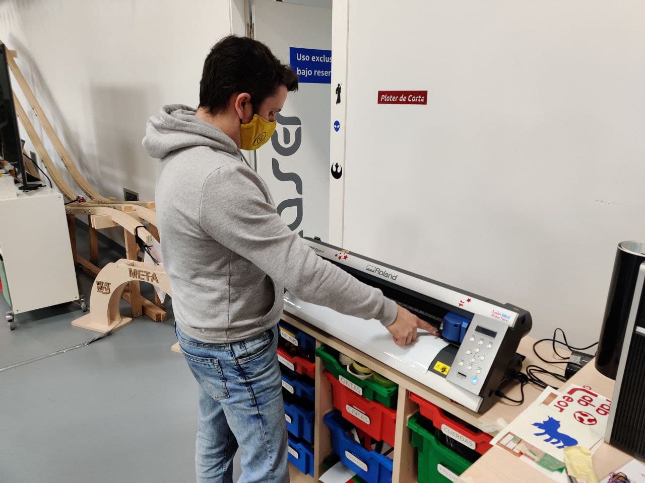
Vinyl cutter⚓︎
A vinyl cutter is a type of computer-controlled machine. Small vinyl cutters look like a desktop printer. Like a printer controls a nozzle, the computer controls the movement of a sharp blade over the surface of the material. This blade is used to cut out shapes and letters from sheets of thin self-adhesive plastic (vinyl). The vinyl can then be stuck to a variety of surfaces depending on the adhesive and type of material. To cut out a design, a vector-based image must be created.
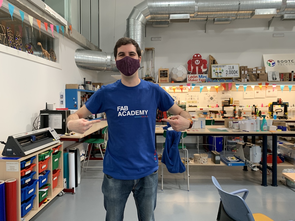
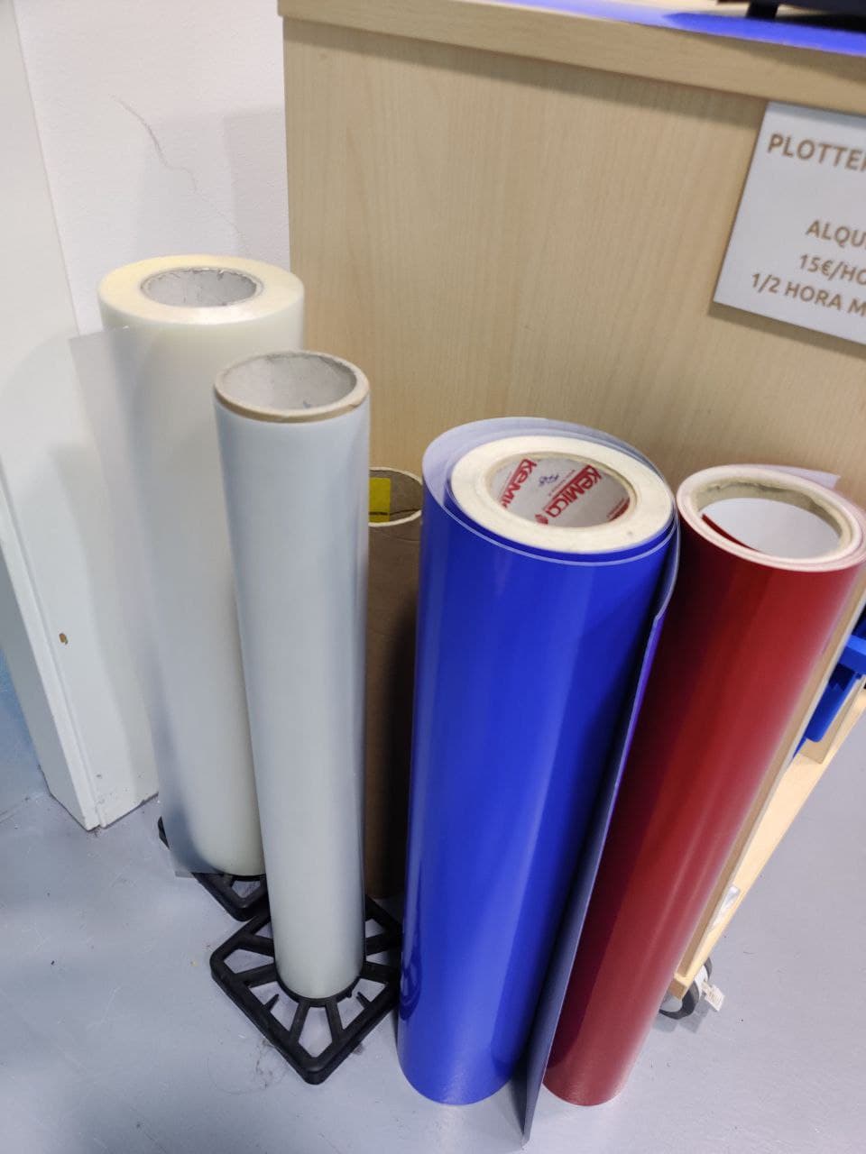
As I am journaling my FabAcademy adventure in a A5 notebook, I decided to vinyl it. Using Inkscape, the FabLab logo design made last week, some text and a minimal drawing I came up with this sticker. Here at FabLab Leon the have a lot of material to choose from, but since I am a beginner I just used a normal white Vinyl. Maybe in the future I will made a t-shirt with textile vinyl as Adrian showed me. His FabAcademy t-shirt looks pretty cool!

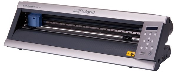
The machine⚓︎
Our warrior for the vinyl cutting thing is the Roland CAMM-1 GX-24 24” Vinyl Cutter. This machine has a group of advanced functions that make it powerful and easy to use at the same time. In fact, it is suitable for people without experience. You can check the user manual for a more in depth walkthrough. Here are the specs:
- Control method: Servo Motor Digital control
- Cutting method: By displacement of the material
- Width of the material to be loaded: From 50 to 700 mm
- Maximum cutting area: Width 584 mm, Length 24998 mm
- Compatible tools: Special blade for CAMM-1 series
- Maximum cutting speed: 500 mm / s (in all directions)
- Cutting speed: 10 to 500 mm / s (in all directions)
- Blade pressure: 30 to 250 gf
- Mechanical resolution: 0.0125mm / step
- Software resolution: 0.025mm / step
Machine operation⚓︎
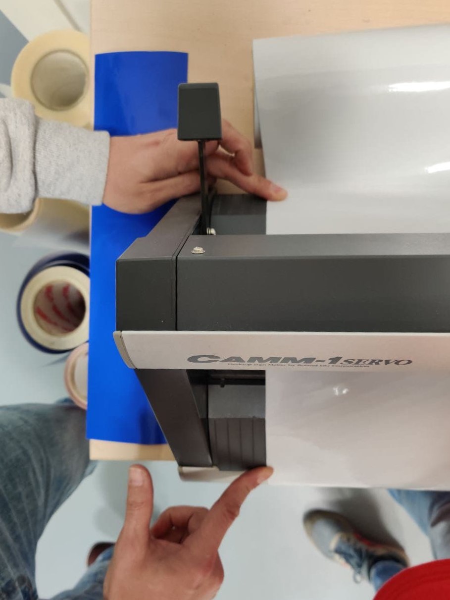
- Turn on the machine
- Open clamp with the handle
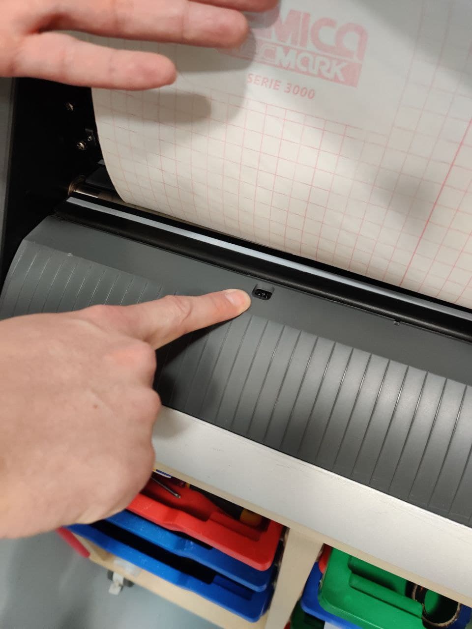
- Put the roll/piece through the rollers
- Aligne with the front and back stripes and close the clamp
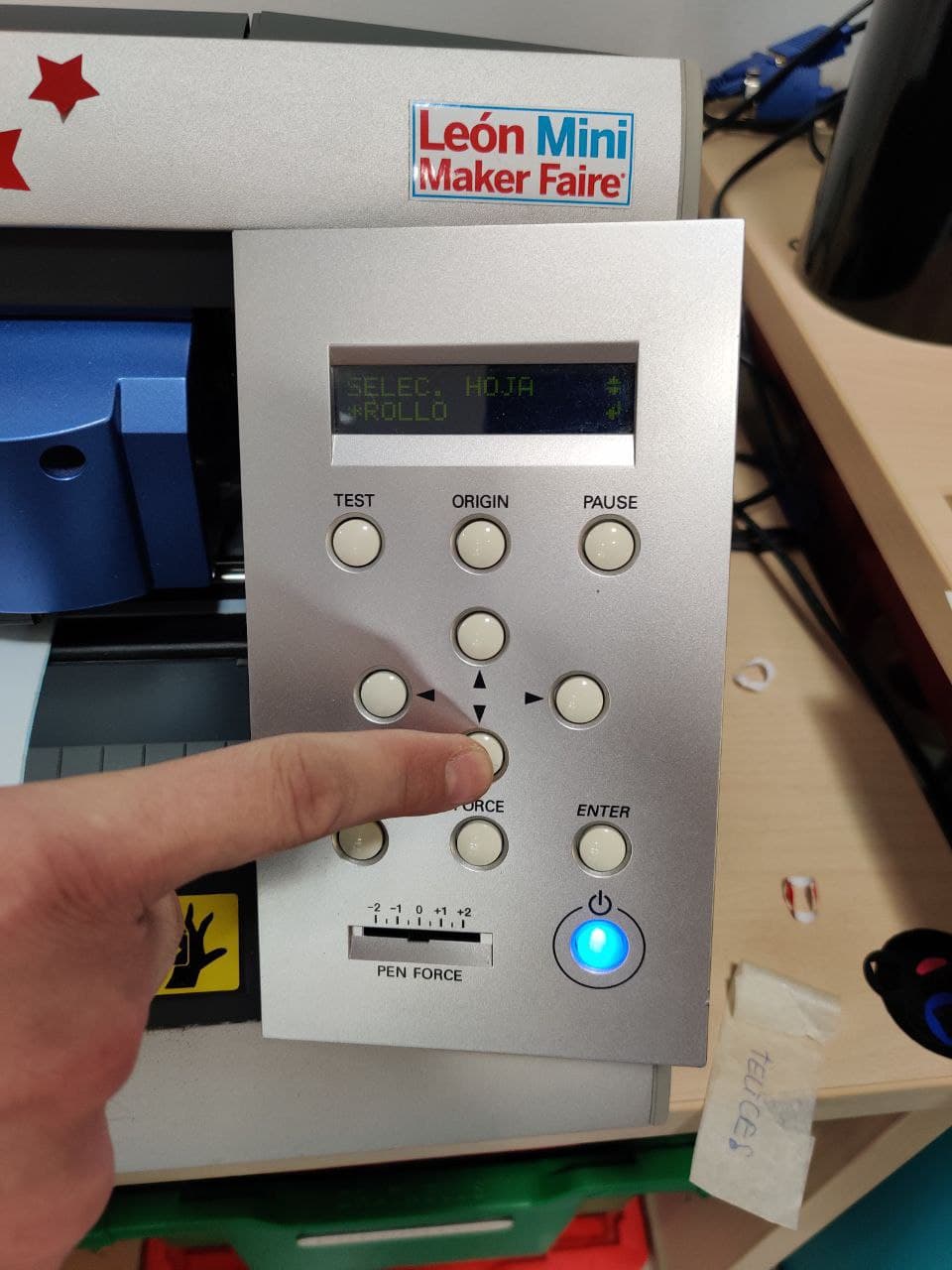
- Select if roll(only width, infinite length)/piece(width and length detected by sensors)
- Press enter, move the roll with the arrows to place it in the edge
- Hold down the button origin
- Displays cutting parameters: speed=18cm/s; blade force=90gf
- Hold down the button test for a quick sample. if the different shapes can be peeled off separately and corner are not torn = correct settings
Software⚓︎
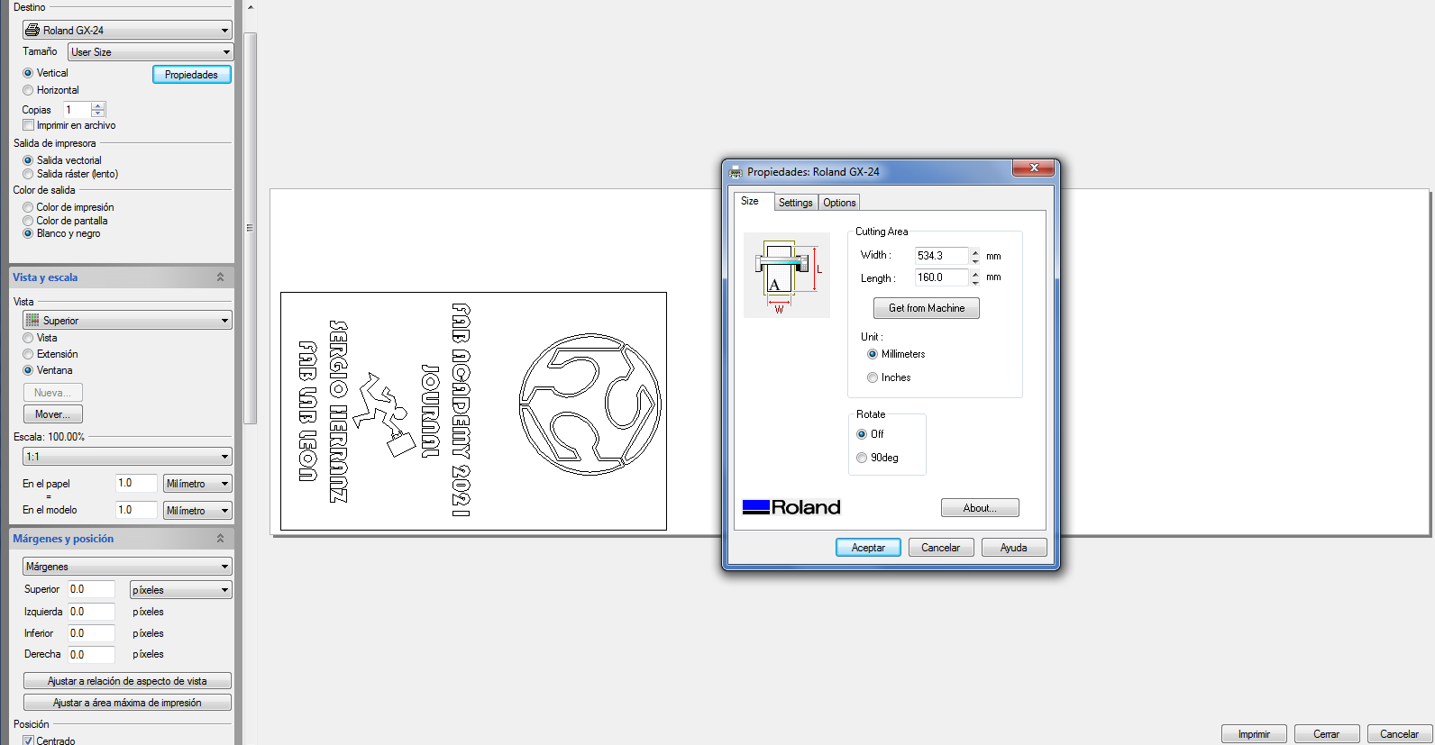
The software is managed through Rhino printing screen, as with the laser cutter, and the embebed Roland driver, so the process of adjusting the design and printing almost identical. The key differences are in the Roland proprietary driver which is pretty easy to use. These are the steps to follow:
- Open the printing screen, select the Roland as the printer and click Properties
- Use the “get from the machine” option for the dimensions of the vinyl we are working with
- Write down those numbers and make a rectangle with matching dimensions
- Put your design inside it and try to adjust it to the bottom, as it’s the start of the roll (try to use a layout that makes the best use of the material)
- Now follow the same process done with the laser cutter to move the rectangle to the one matching your design.
- Clicking printing makes the machine start working straight forward, so make sure to make a last check for the settings.
Peeling off⚓︎
Once is cutted we can cut the material and start peeling off the extra vinyl. We can use the remaining piece for new cuts. When we have already eliminated the vinyl that does not belong to our design, we have two options: If it is a single piece, we can take it off and use it freely, but if there are many small ones like this case, peeling off and sticking one by one would be quite a tedious process.

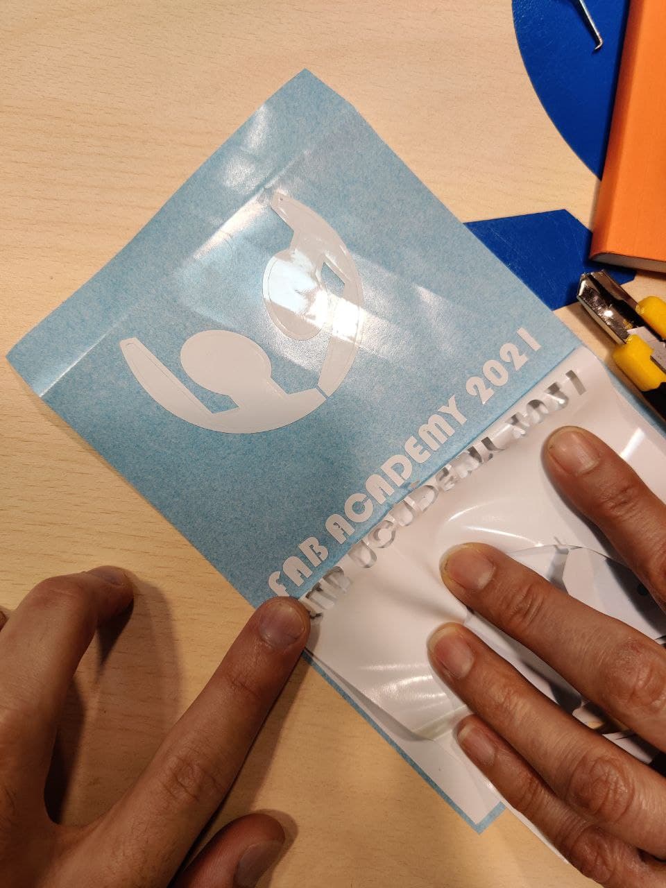
This is where Nuria appeared to save me an hour of work and a bad result. We can use a transparent adhesive paper, like the one used to cover books, to use it as a transfer element. If we place it on the unpeeled vinyl and we make sure that all the elements are well adhered, then we can stick it directly on our notebook!
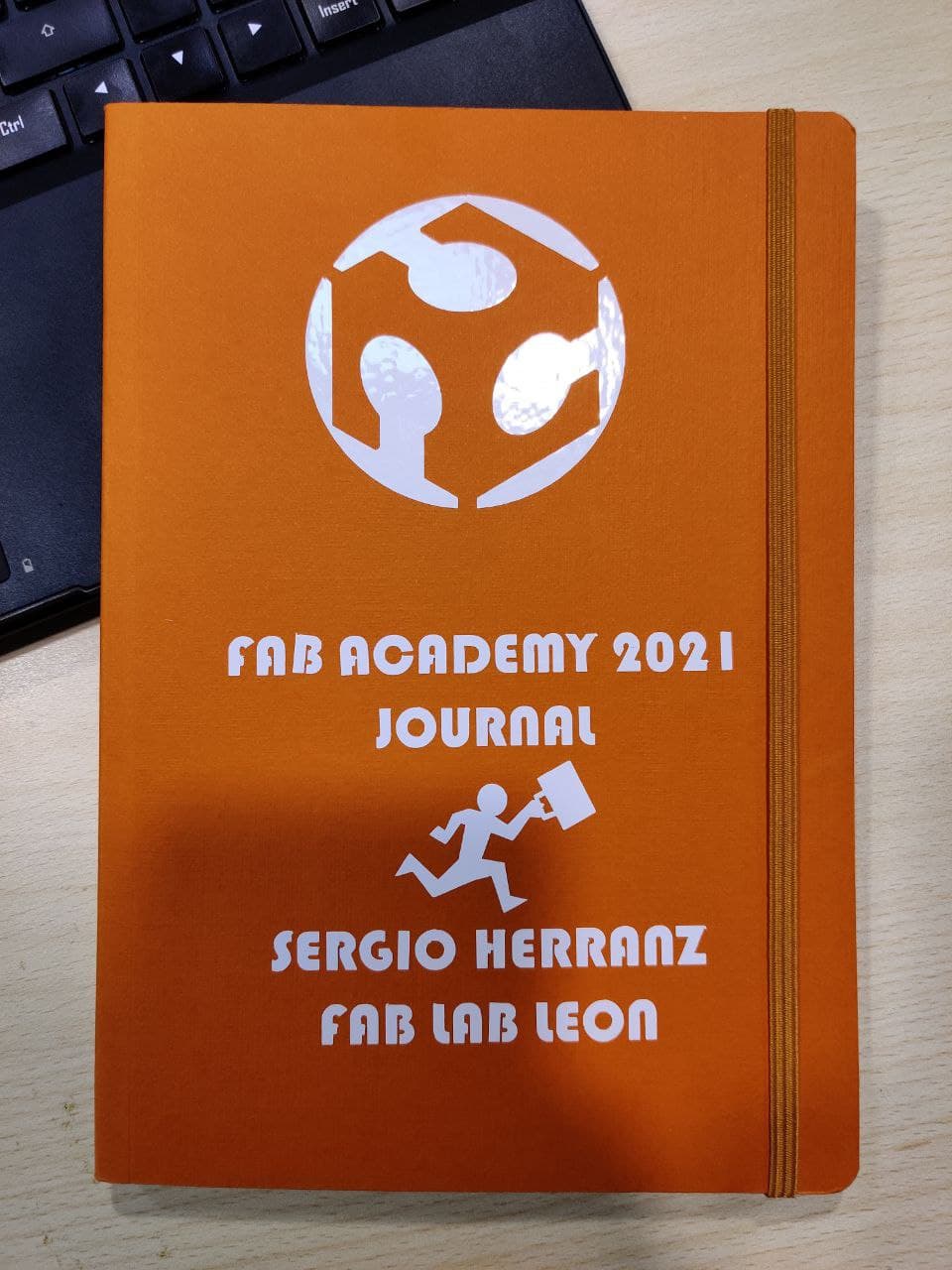
Final result⚓︎
The truth is that it turned out quite cool, although I am afraid that by not having protection the letters will come off. I could start a company of custom notebooks… maybe i can name it… moleskine? 
Extra⚓︎
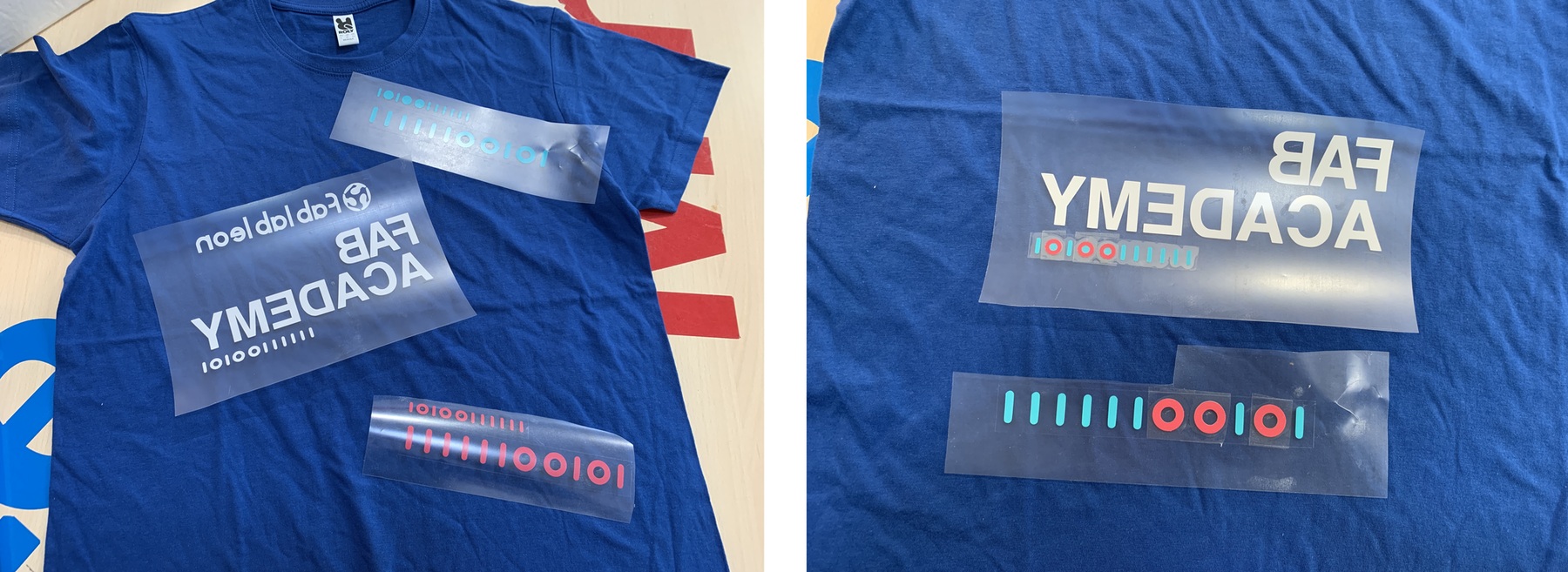
This is an update from two month after. It was my brother’s birthday so I decided to give him a custom sweatshirt with a logo I made for him some time ago, of a life project he has. It’s called Two Towns Further, you can check his instagram if you want @twotownsfurther.
For the case I used special vinyl for textiles and then used the heat iron to stick de design to the back. My instructor Pablo helped me with the sticking process, but the workflow cutting vinyl with the machines has been quite easy thanks to this documentation, so I guess it made the job! Here are some photos of the process.
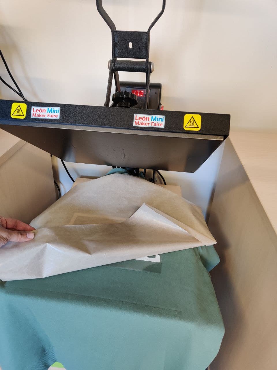

He liked it a lot! I’ll try to submit a photo of him wearing the clothes and the matching with the the project.
Files⚓︎
- Jesus original grasshopper files from FabAcademy 2019(
.gh): file - Jesus files modified for Rhino and lasser cutting(
.3dm): file - Pressfit test designed by me for laser cutting(
.3dm): file - Final wall shelf iteration parametric design(
.f3d): file - Final wall shelf iteration pressfit kit(
.3dm): file - Vinyl design for notebook front page(
.svg): file