10/11. Mechanical and machine design⚓︎
-
- Design a machine that includes mechanism + actuation + automation.
- Build the mechanical parts and operate it manually.
- Actuate and automate your machine.
- Document the group project.
-
Individual assignment
- Document your individual contribution.
-
Learning outcomes
- Work and communicate effectively in a team and independently.
- Design, plan and build a system.
- Analyse and solve technical problems.
- Recognise opportunities for improvements in the design.
-
Have you?
- Documented the machine building process to the group page.
- Documented your individual contribution to this project on your own website.
- Linked to the group page from your individual page as well as from group page to your individual pages.
- Shown how your team planned and executed the project (Group page).
- Described problems and how the team solved them (Group page).
- Listed future development opportunities for this project (Group page).
- Included your design files (Group page).
- Optionally included an aprox. 1 min video (1920x1080 HTML5 MP4) + slide (1920x1080 PNG) (Group page).
Group assignment⚓︎
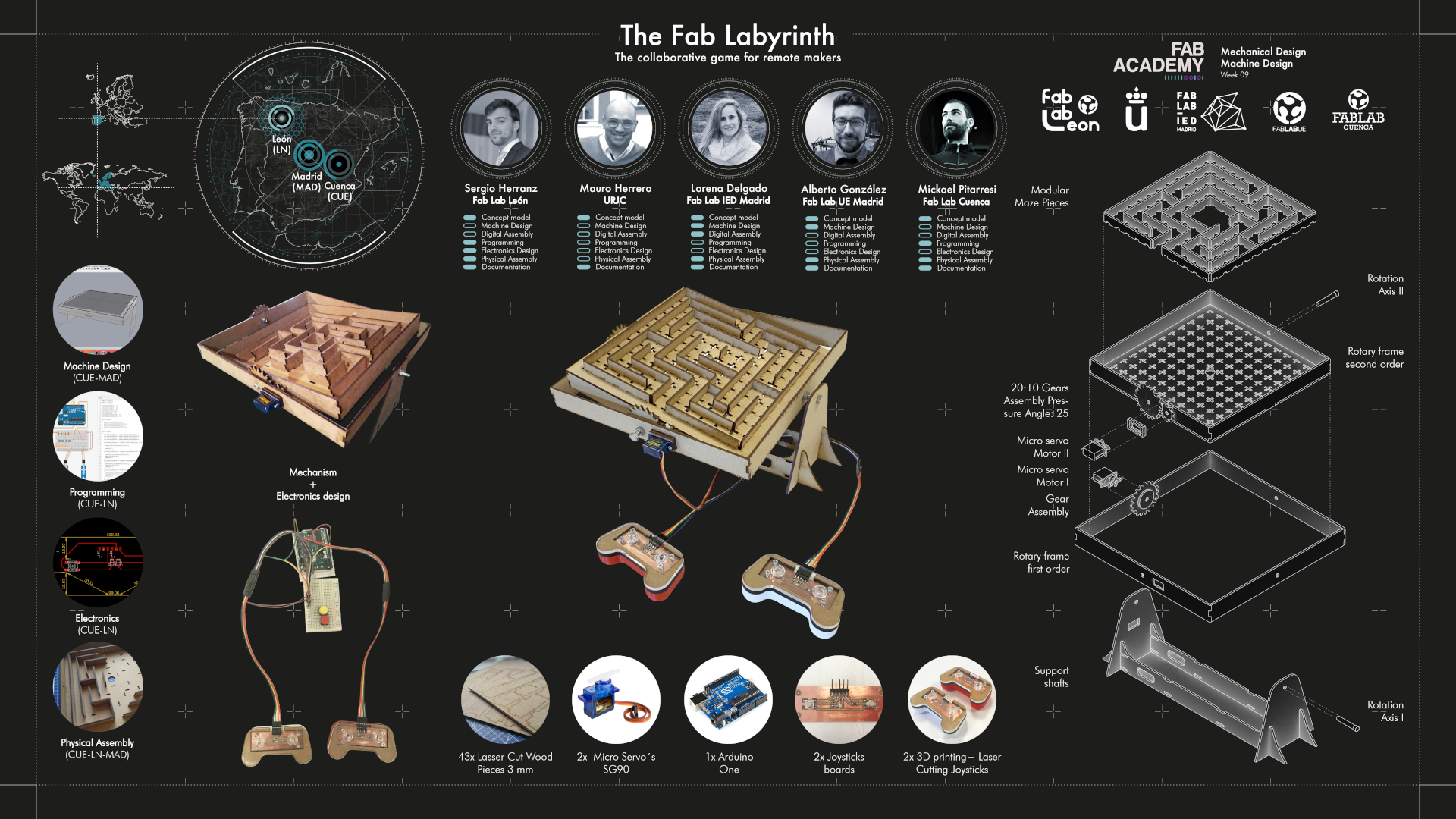
First I encourage you to visit the Group Assignment page of FabLab Leon, where all the work for the machine is documented. There you can see the final machine, our journey through the process and all the team work and individual contribution. Below you can find attached the final slide of the machine and the video for the presentation.
Situation⚓︎
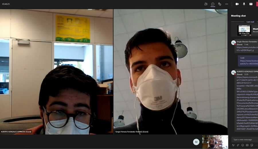
Our situation is not so common so I’ll take a minute to explain it. We are 5 students in Leon’s node this year but I’m the only one of us physically here. Mickael co-runs FabLab Cuenca, so he is in Cuenca. Lorena, Mauro and Alberto are in Madrid. Lorena works in FabLab IED. Alberto is the coordinator of FabLab UE (Universidad Europea of Madrid). Mauro usually works in URJC. However, the virus hit the team hard. Mauro tested positive a couple of weeks ago and has been in the hospital with a respirator for more than a week. Even if he’s evolving nicely and he’s at home now, his participation in the assignment could not be as active.
To get into work, we have divided the tasks as follows. Mickael and I would work on the code. I would be the programmer and Mickael, as he would be the only one with access to his FabLab during Easter week, could build the first machine and de-bug the design and the code. Alberto would engineer the machine, the mechanisms, the position of the servos and the interaction of the parts. Lorena would work on the visual part, creating the slides and the documentation. She was also responsible for the design of the maze itself.
Slide⚓︎
Video⚓︎
Individual assignment⚓︎
As if it were the beginning of a novel, it could be said that all started a long time ago… To be precise, on February 27th, but I don’t want to get dramatic!  Our instructors advised us to meet beforehand with the intention of defining the idea of the machine we wanted to make, so that if it was necessary to buy any material to assemble it, we could have everything available this week. Also, since the rest of my colleagues are attending FabAcademy remotely from Madrid, the intention was to meet all of us here in FabLab Leon the weekend of the assignment to complete the work.
Machine choice⚓︎
Our first meeting was a brainstorming session, where we all came up with various concepts. Mauro discovered the Fabricatable Machines and proposed that we use these modules to design a small milling machine that he had been thinking about making for some time. Mickael also proposed us to make an Acrylic Bending Tool, which reminded me of this project that I had seen some time ago on a youtube channel that I frequently follow: Acrylic Bending Machine. This second idea was the one that excited us the most, and we started to imagine possible prototypes and working spirals.
After consulting the machine idea with our instructors, they have told us that it couldn’t be enough to pass the assignment due to lack of shafts. Even if we automate the rolling bed it wouldn’t meet the assesment guide, so sadly, we have discarded the acrylic bending machine. This has led to a new brainstorming session to make a final choice about the machine we want to make.

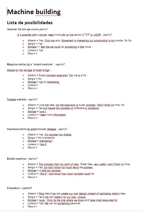
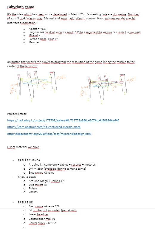
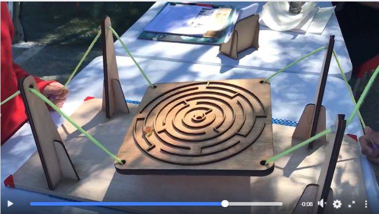
After many meetings, many ideas and many yelling, we decided to create a machine that could be interactive, like a game, that could be collaborative, easy to replicate and easy to set up. We came up with the FabLabyrinth. It is a machine to solve mazes.
It would have a surface on top where we could change the labyrinth, making it modular or interchangeable. It would have servos or step motors that would move that platform in two axis: roll and pitch. And it would have two controllers and some buttons that would do the different actions.
We wanted the machine to have different modes to play. The “self solving” mode would be the full automation of the machine, following a code and moving on its own to solve the maze. The “collaborative” mode would let you control the machine with the two controllers. Each player would control each of the servos or motors, so with the movements of both of them combined the machine would move in the correct direction for the ball to move through the maze. We also wanted the machine to be so easy to replicate that we could have one on each of our FabLabs.
Prototyping⚓︎
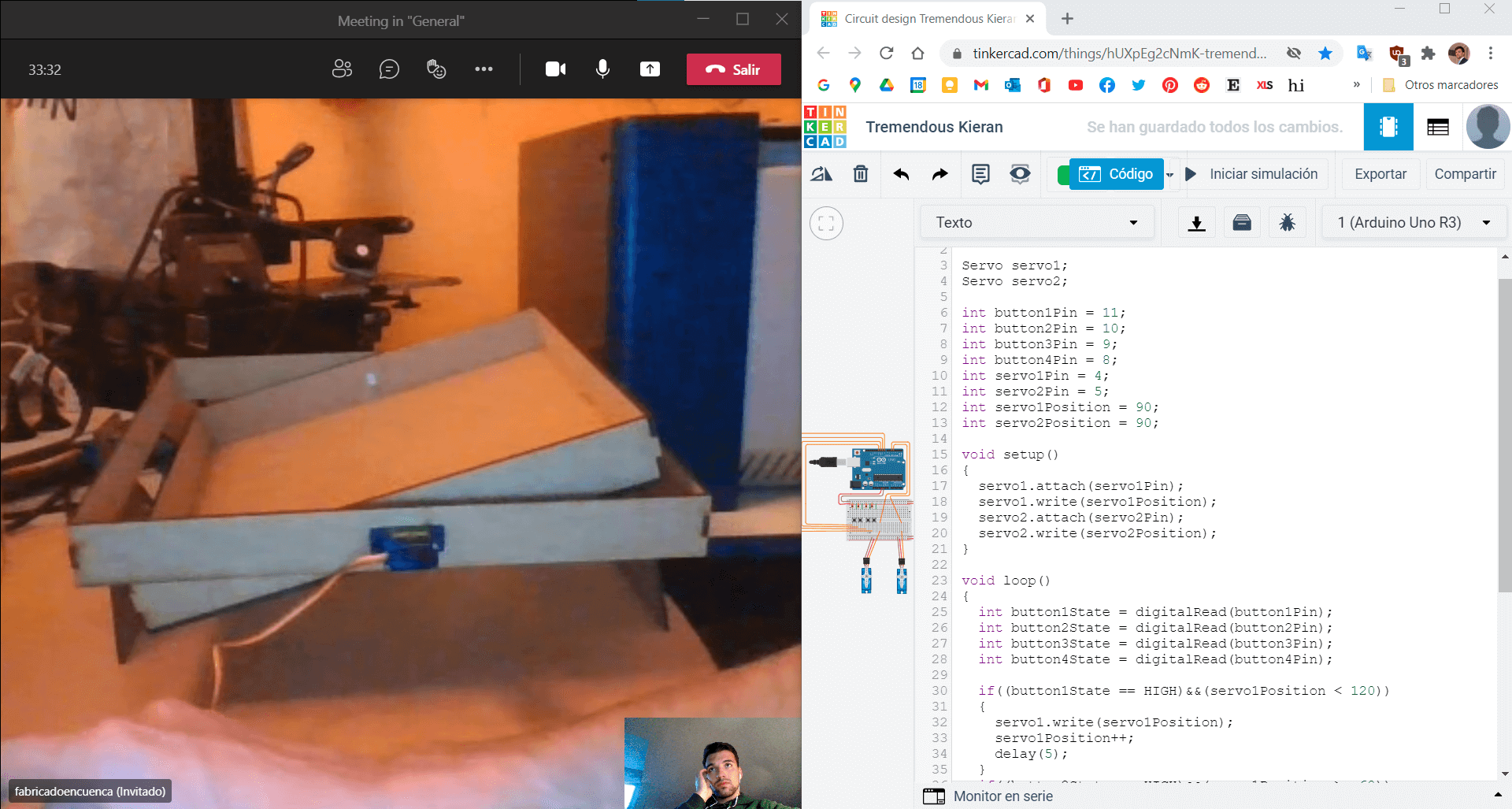
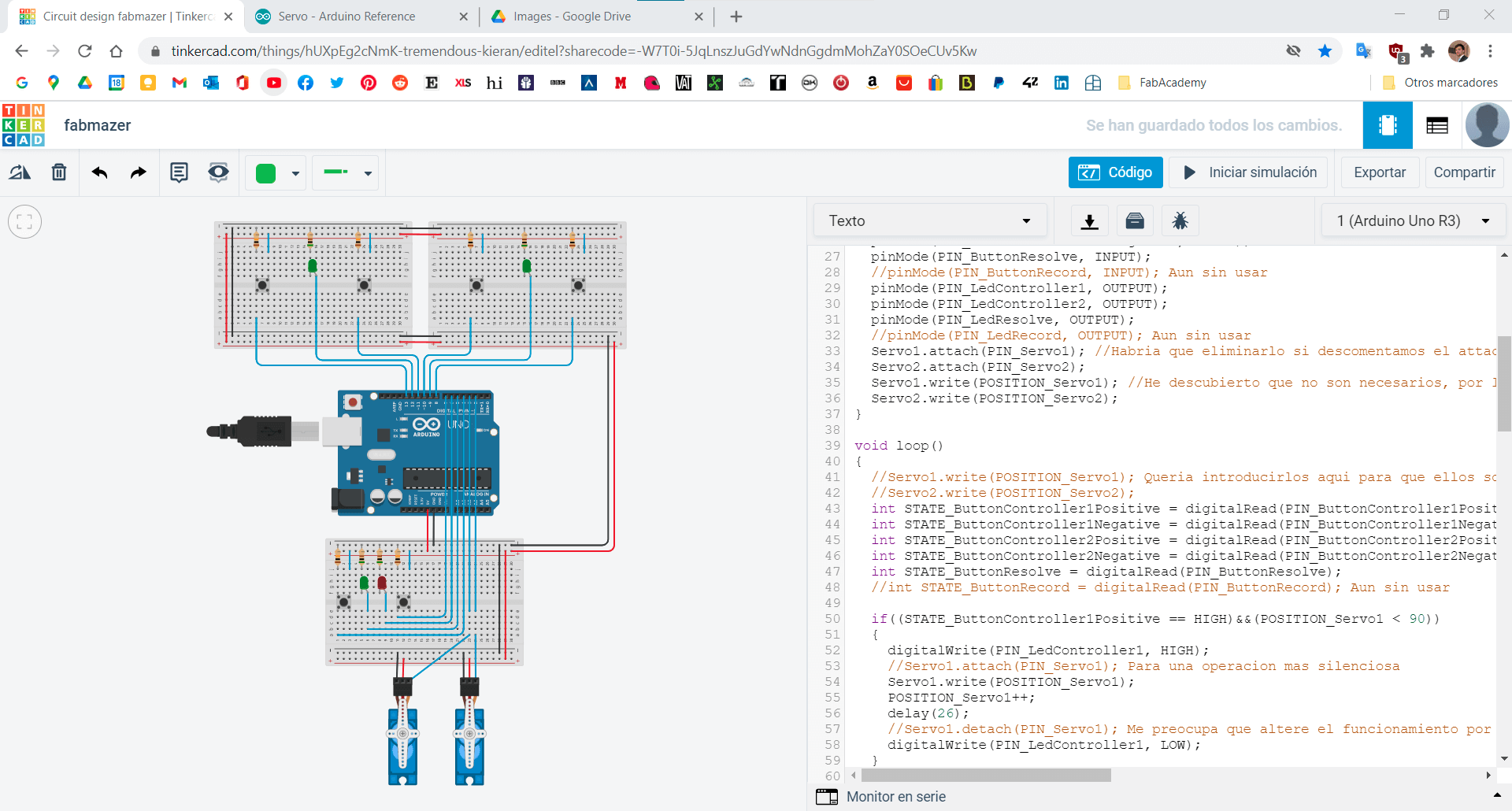
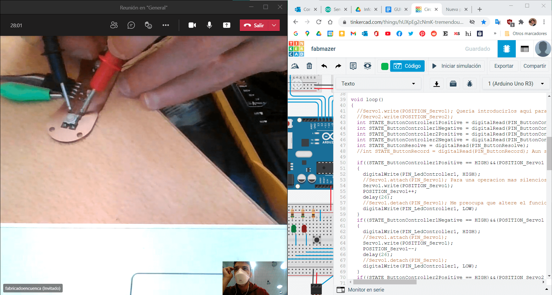
Onto the first hardware iteration. Mickael started by investigating the use of servo motors with an arduino and mounted on a breadboard the first draft of what could be the controls of the game. x4 buttons + resistors connected to their pins along with the 5v and pins for the motors. He went on and tried to implement the code explained in this tutorial but he couldn’t make it work. He also made a project in Tinkercad to make the development and testing easier and more accessible to all.
For the second software iteration. I started working together with Mickael through Tinkercad to fix the non working code. There were some problems with the variable names (bad typing), as the code was written directly from the tutorial, so the Arduino IDE was screaming a bunch of errors when verifying the code. Bad initialization, position or syntax of some variables (despite it was the same from the tutorial) where most of them. Then we took our time to understand the order in which the code had to operate to function and finally got a simple code that was functional. After making it work, Mickael assembled the machine and we started tweaking the movement through software. The journey for the software development continues below


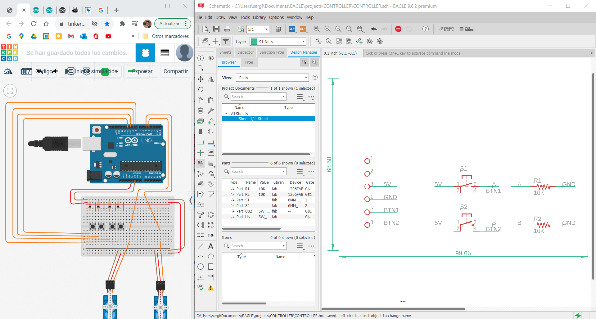
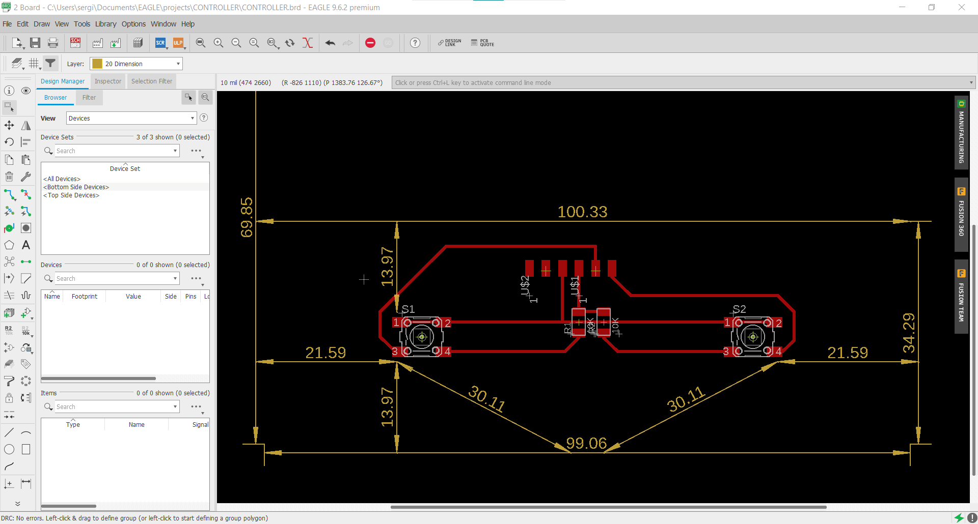
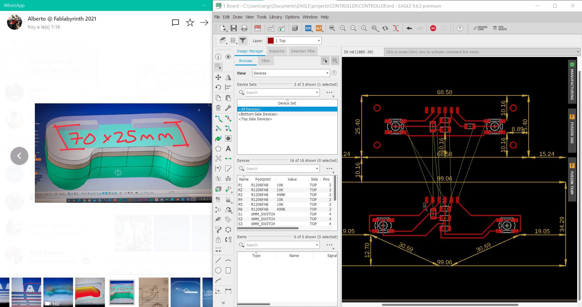
Electronic design⚓︎
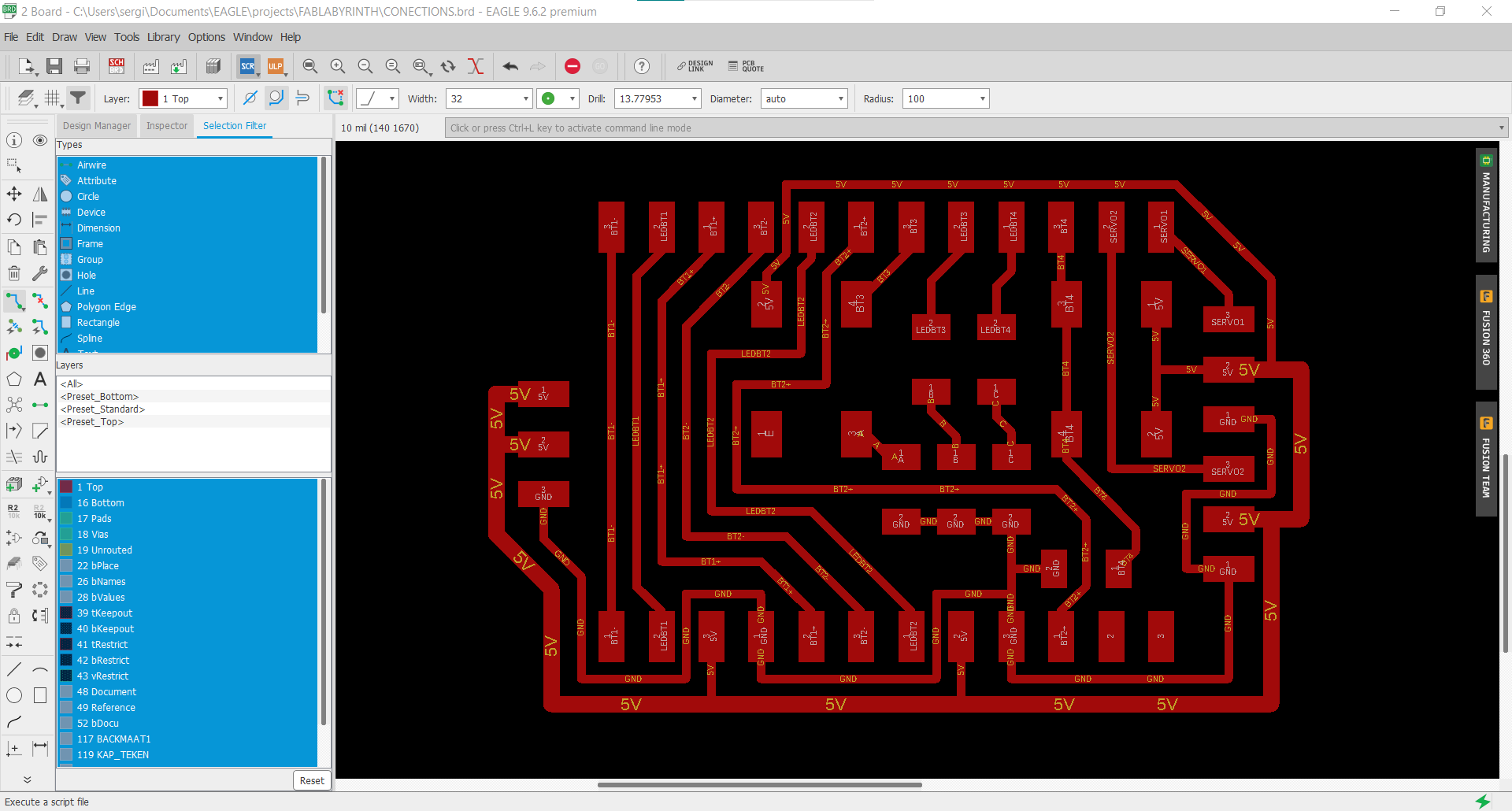
At the same time I started designing the board for the controllers, as we decided to make them independent from the main board. The controller will have two buttons, to turn to one side or another of it’s axis (servo), and a led to know when it’s operating. The buttons and leds for the record and resolve future functions will be in the main board. The main board, or connections board, will be like a passthrough to connect all the wires to it and control the game modes. A great design will be to make it with through hole pins to stack directly on top of the arduino, like an Arduino Mega and Ramps boards.
Custom code⚓︎
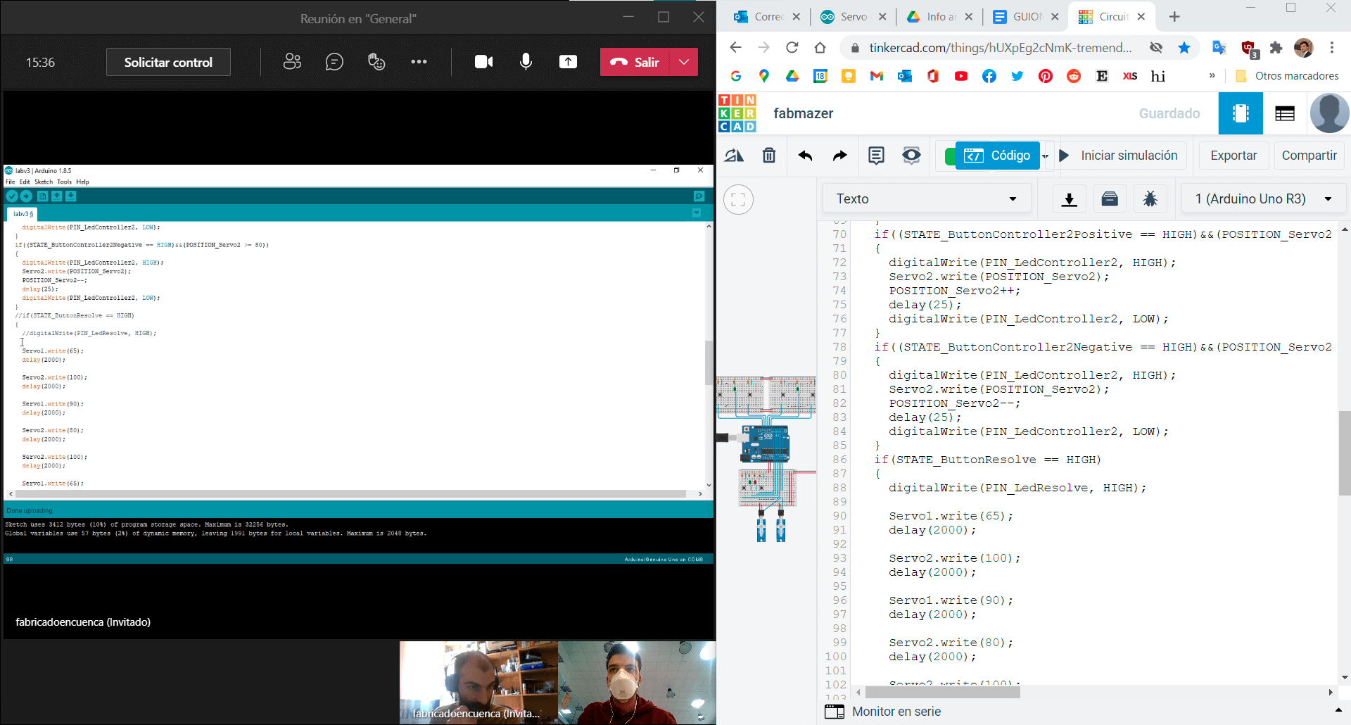
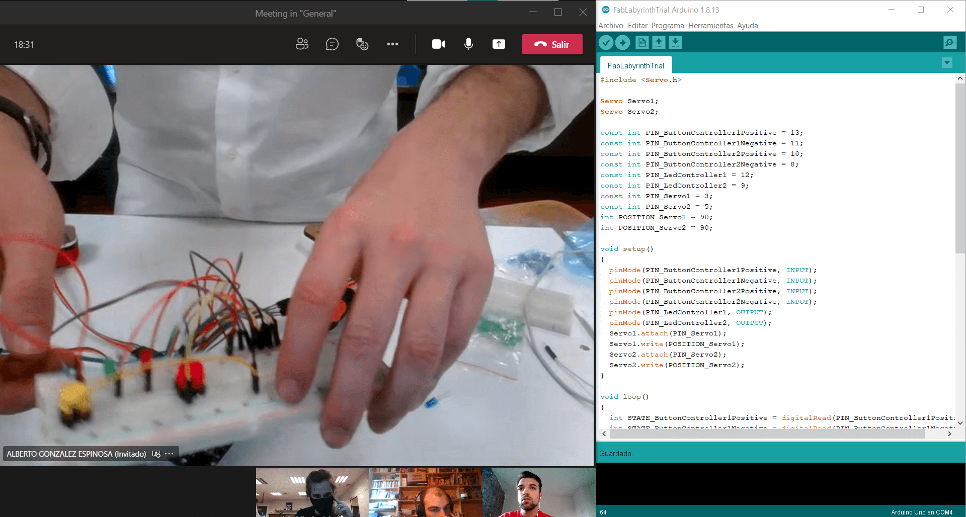
After Mickael assembled the machine, we started tweaking the code for better response and efficiency. We limited the servo’s angle range with some if terms, slowed down it’s speed of them by increasing the delay time, tried removing the noise/humming from the motors, customized the angle range to each motors as the low quality make them imprecise (Mickael was modifying the parameters and seeing how the machine was responding and I was looking for functions to make it more silent and precise). Later Mickael made the code that makes the machine solve the maze alone by simply giving it the instructions step by step. This code will be putted together with the first code we have for the game controls.
For the final software iteration, as code was getting complex and components didn’t fit clearly in one board, I decided to redo the TinkerCad schematic to separate each board and get a clearer view of each component and it’s function in the code. I also implemented new variables for the resolve function and included it as a new function in the main code. Record will be implemented later as it needs to use arrays and it’s far more complex.
#include <Servo.h>

Servo Servo1;
Servo Servo2;

const int PIN_ButtonController1Positive = 11;
const int PIN_ButtonController1Negative = 13;
const int PIN_ButtonController2Positive = 8;
const int PIN_ButtonController2Negative = 10;
const int PIN_LedController1 = 12;
const int PIN_LedController2 = 9;
const int PIN_Servo1 = 3;
const int PIN_Servo2 = 5;
int POSITION_Servo1 = 82;
int POSITION_Servo2 = 90;

void setup() {
    pinMode(PIN_ButtonController1Positive, INPUT);
    pinMode(PIN_ButtonController1Negative, INPUT);
    pinMode(PIN_ButtonController2Positive, INPUT);
    pinMode(PIN_ButtonController2Negative, INPUT);
    pinMode(PIN_LedController1, OUTPUT);
    pinMode(PIN_LedController2, OUTPUT);
    Servo1.attach(PIN_Servo1);
    Servo2.attach(PIN_Servo2);
}

void loop() {
    int STATE_ButtonController1Positive = digitalRead(PIN_ButtonController1Positive);
    int STATE_ButtonController1Negative = digitalRead(PIN_ButtonController1Negative);
    int STATE_ButtonController2Positive = digitalRead(PIN_ButtonController2Positive);
    int STATE_ButtonController2Negative = digitalRead(PIN_ButtonController2Negative);

    if((STATE_ButtonController1Positive == LOW)||(STATE_ButtonController1Negative == LOW)||(STATE_ButtonController2Positive == LOW)||(STATE_ButtonController2Negative == LOW)) {
        Servo1.write(POSITION_Servo1);
        Servo2.write(POSITION_Servo2);
        Servo1.detach();
        Servo2.detach();
    }

    if((STATE_ButtonController1Positive == HIGH)&&(POSITION_Servo1 < 180)) {
        Servo1.attach(PIN_Servo1);
        digitalWrite(PIN_LedController1, HIGH);
        Servo1.write(POSITION_Servo1);
        POSITION_Servo1++;
        delay(20);
        Servo1.detach();
        digitalWrite(PIN_LedController1, LOW);
    }

    if((STATE_ButtonController1Negative == HIGH)&&(POSITION_Servo1 >= 0)) {
        Servo1.attach(PIN_Servo1);
        digitalWrite(PIN_LedController1, HIGH);
        Servo1.write(POSITION_Servo1);
        POSITION_Servo1--;
        delay(20);
        Servo1.detach();
        digitalWrite(PIN_LedController1, LOW);
    }

    if((STATE_ButtonController2Positive == HIGH)&&(POSITION_Servo2 < 180)) {
        Servo2.attach(PIN_Servo2);
        digitalWrite(PIN_LedController2, HIGH);
        Servo2.write(POSITION_Servo2);
        POSITION_Servo2++;
        delay(20);
        Servo2.detach();
        digitalWrite(PIN_LedController2, LOW);
    }

    if((STATE_ButtonController2Negative == HIGH)&&(POSITION_Servo2 >= 0)) {
        Servo2.attach(PIN_Servo2);
        digitalWrite(PIN_LedController2, HIGH);
        Servo2.write(POSITION_Servo2);
        POSITION_Servo2--;
        delay(20);
        Servo2.detach();
        digitalWrite(PIN_LedController2, LOW);
    }
}
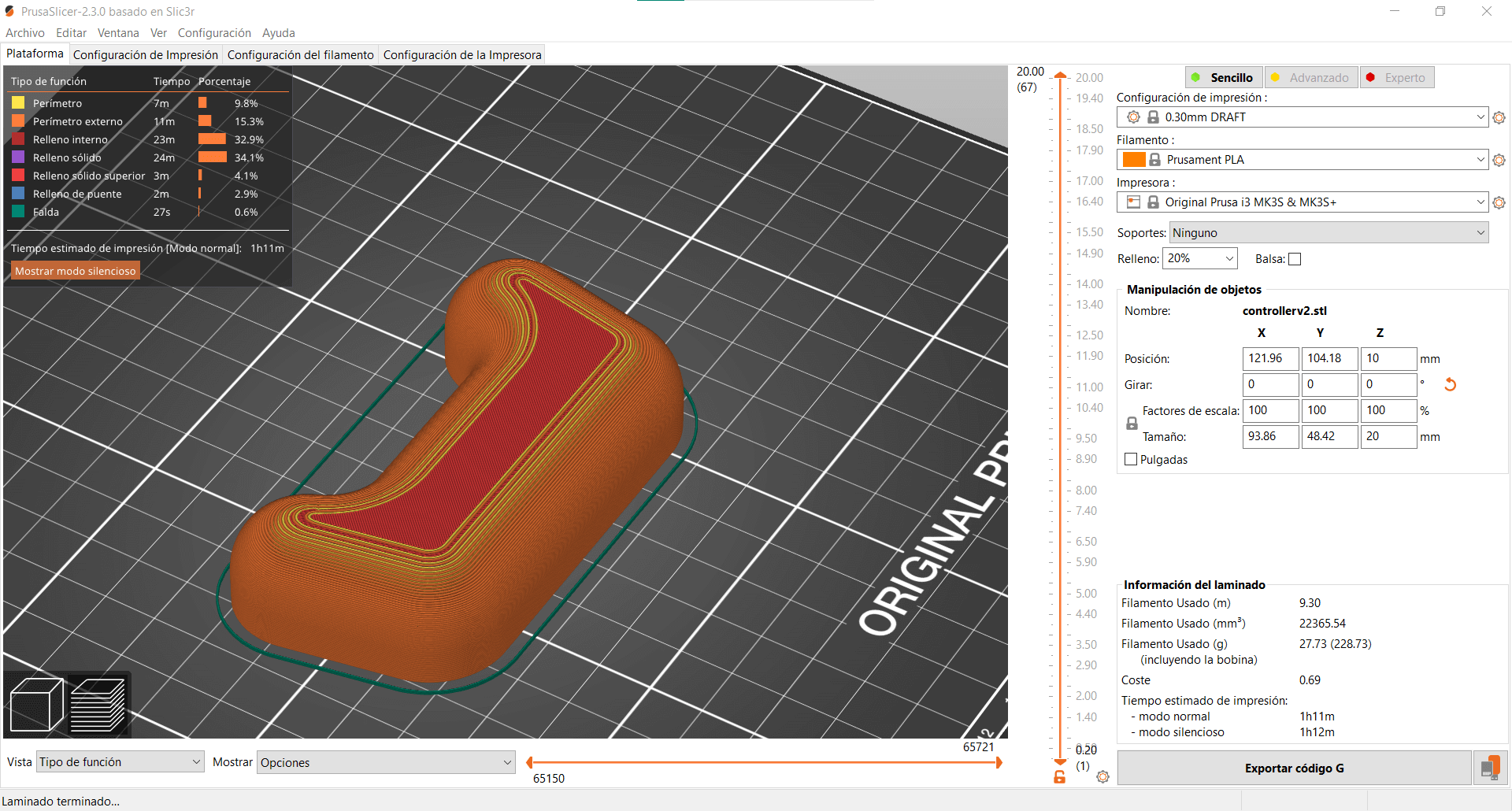
Fabrication⚓︎
My collegues fabricated the controllers board so I have to give them some instructions abour how was the design planned to be. I also printed some 3D parts to give feedback to Madrid, were the main machine was being made. Finally Mickael and I guided Alberto and Lorena through the schematic for the final electronics assembly. At the end Alberto was testing everything and giving me feedback to tweak the code, so it was like an on demand debugging sesion. They were asking, I was modifing the code live and sending it to them, again and again.
Files⚓︎
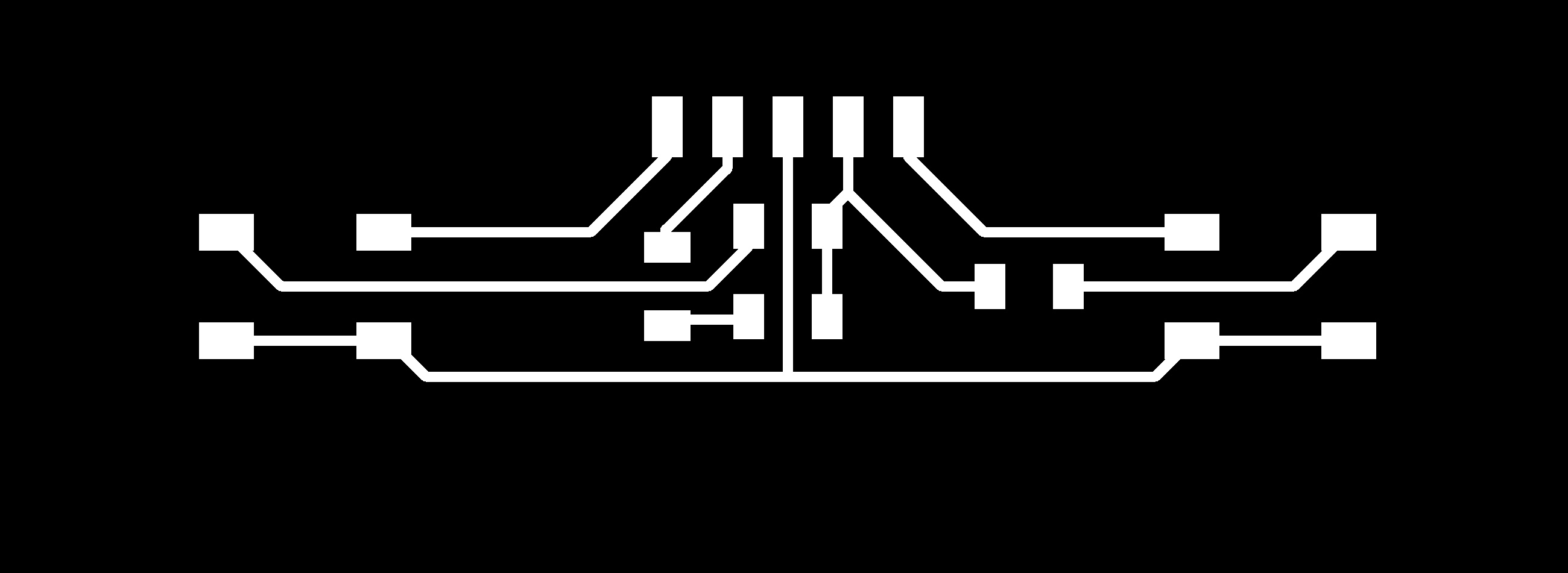
- Schematic design from Eagle of the Controller board (
.sch): file - Board design from Eagle of the Controller board (
.brd): file - Schematic design from Eagle of the Connections board (
.sch): file - Board design from Eagle of the Connections board (
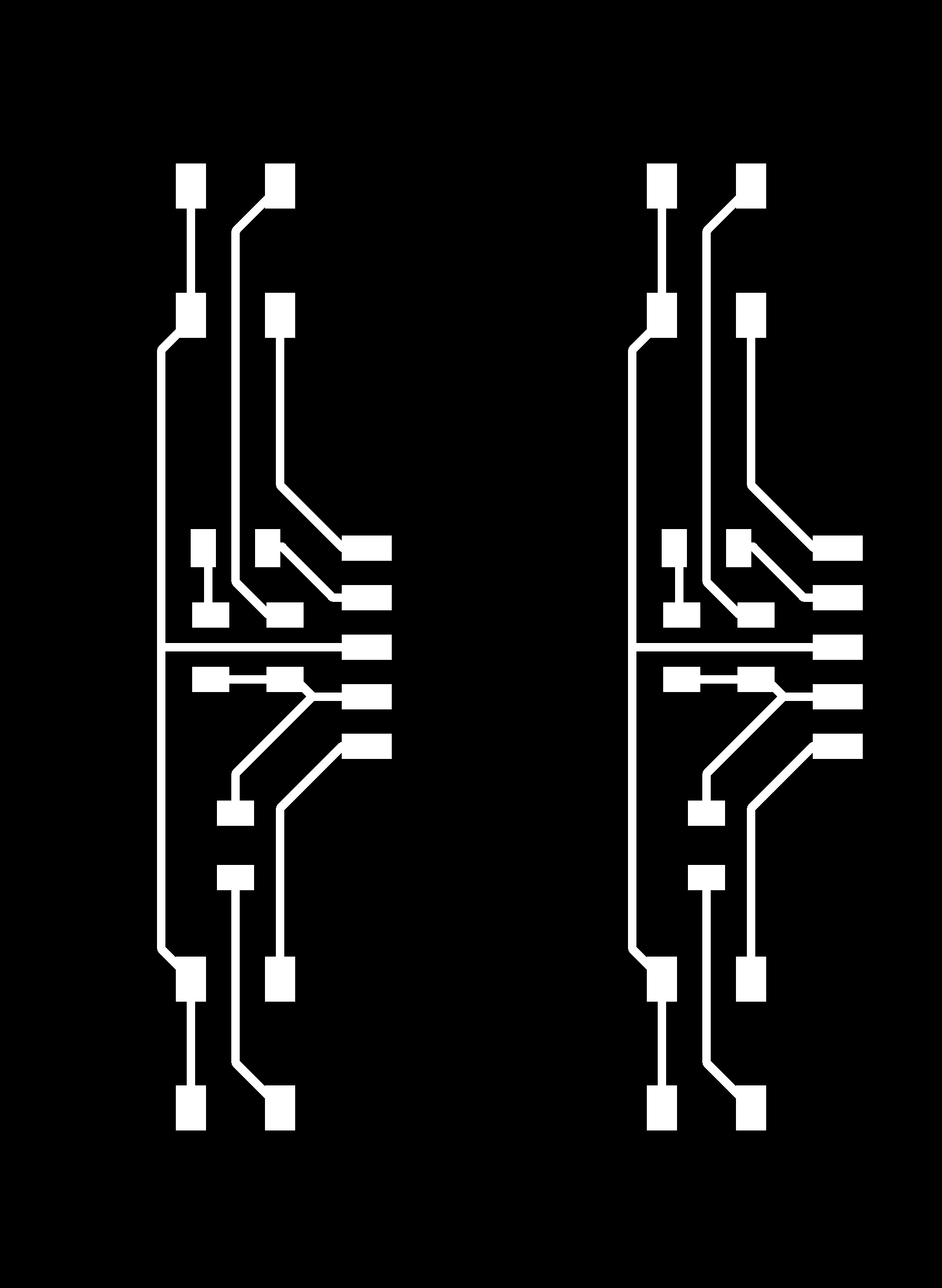
.brd): file - Traces of the Controller board (
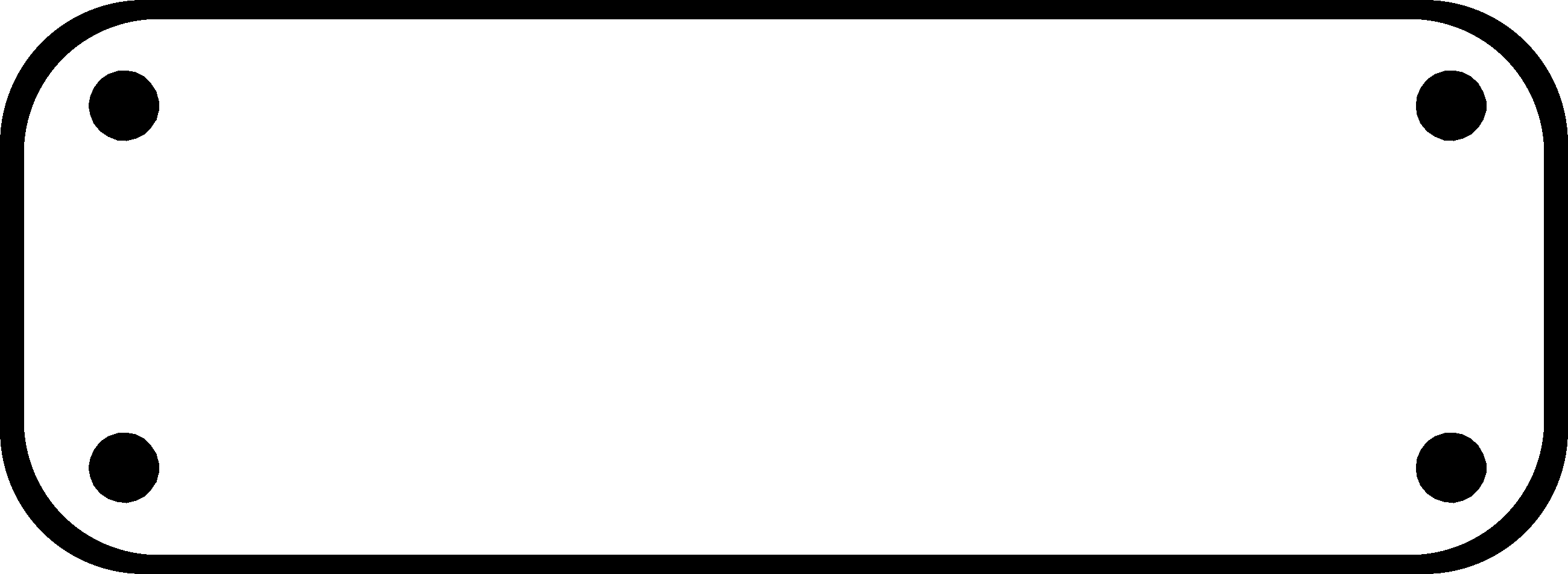
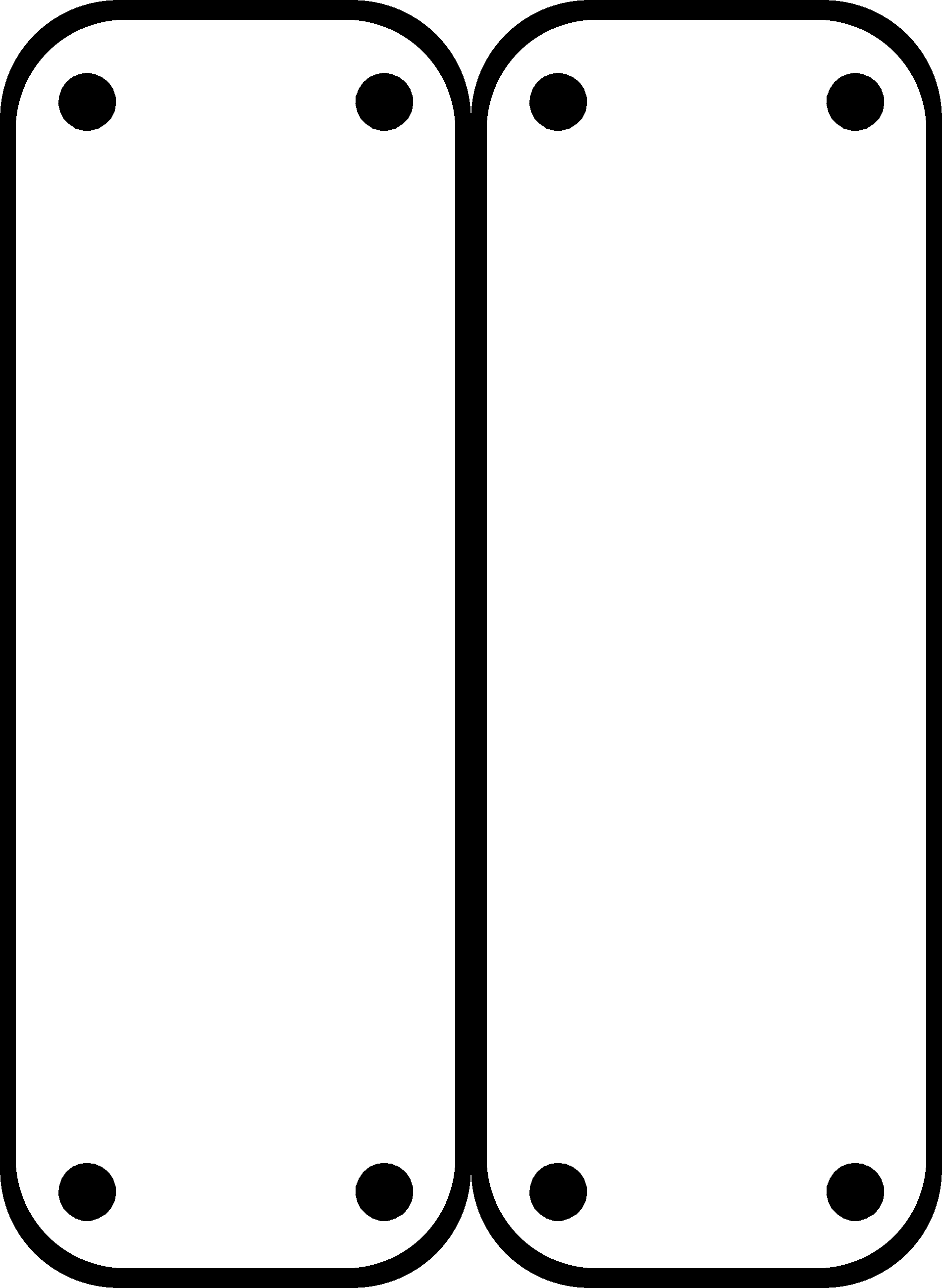
.png): file - Exterior of the Controller board (
.png): file - Dual traces of the Controller board (
.png): file - Dual exterior of the Controller board (
.png): file - Traces of the Connections board (
.png): file - Exterior of the Connections board (
.png): file - Arduino code for FabLabyrinth playing option V5 (
.ino): file