Project development⚓︎
Development plan⚓︎
Time management⚓︎
Five weeks before the final project presentation, I had a meeting with my instructor Pablo to stablish the development plan and time management for the final project. We did a planning by objectives, trying to fulfill spirals in specific periods of time, so that the ideation process would not be delayed in order to move quickly to the manufacturing process. In the photo taken from the blackboard, this planning appears at the bottom right.
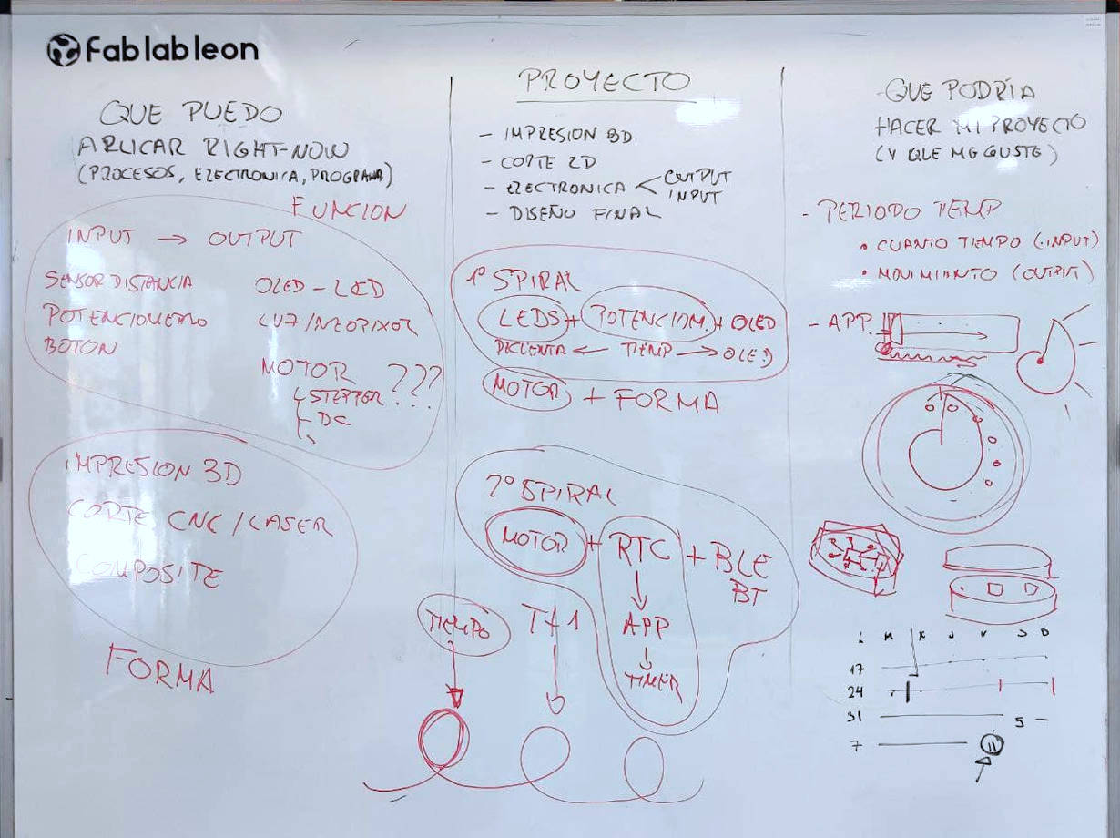
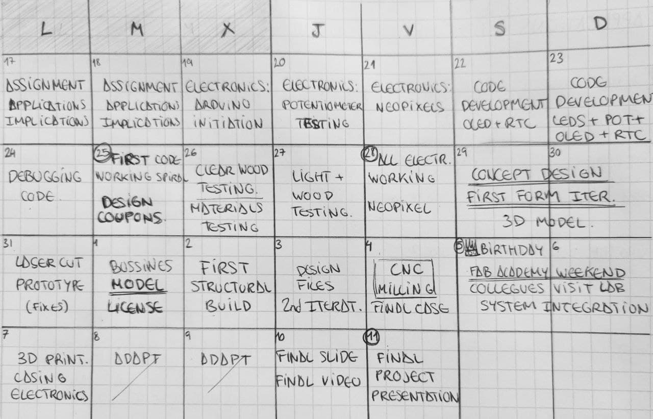
Over the weeks the deadlines have been lengthening and I have not managed to meet these objectives. I’ve been basing the working program on small set goals of two in two days. Finally the planning was totally dependent on the needs that arose to complete the project. It is by no means an ideal system, but in my case it has worked for me because my instructions have been setting me in some way the necessary goals to deliver the project.
Assignments background⚓︎
Throughout the weeks of FabAcademy I have tried to focus my assignments on making and learning about the components that I thought would make up my final project. Finally, only a few of the things I have tested during the assignments are going to be used in the project but I’ll be probably using all what I’ve learned through them. These is a summary of the skills obtained that I am likely to use in my final project:
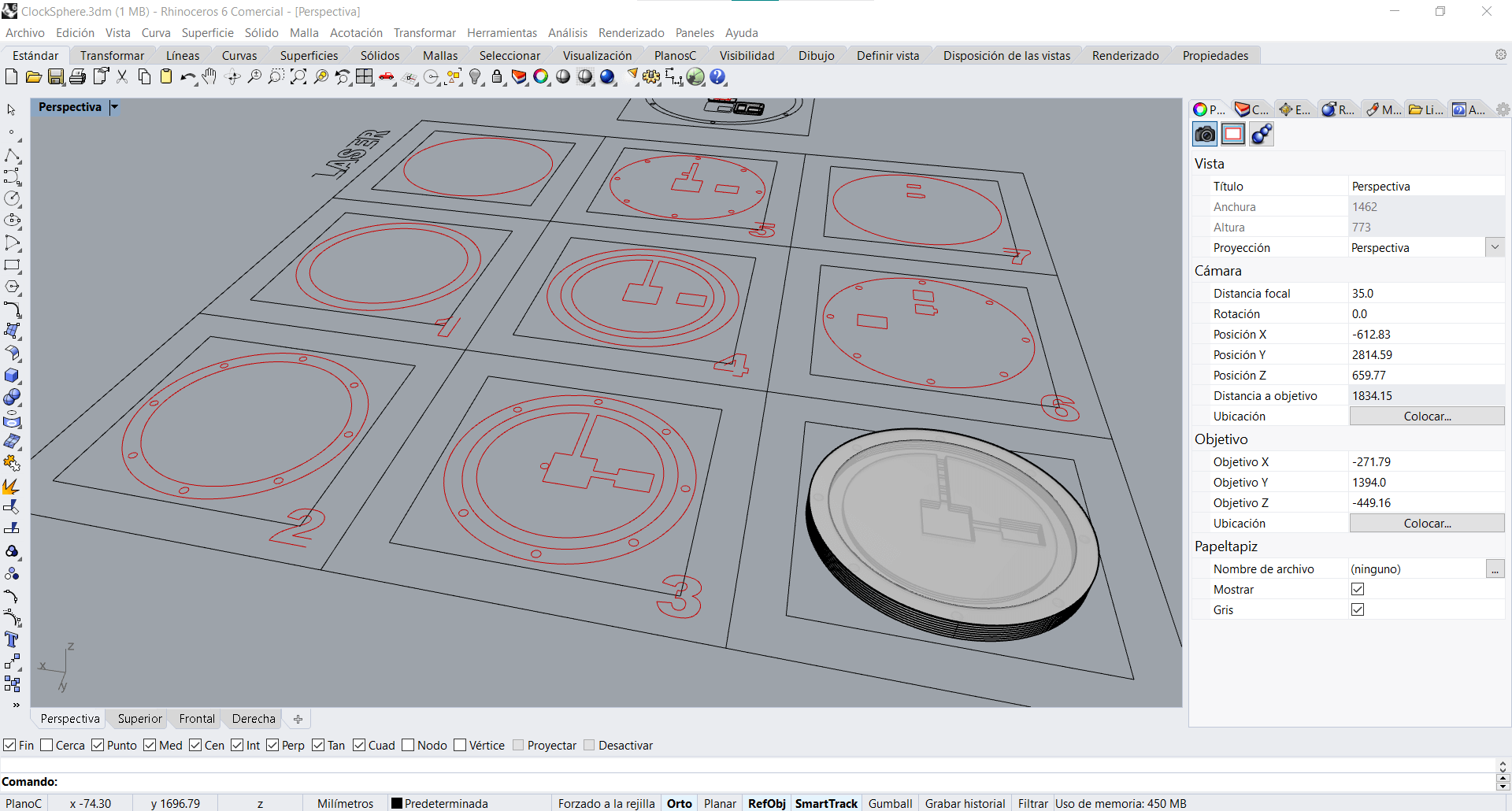
- Computer Aided Design assignment: I’ll probably use Rhino for the 3D model and all the vector needed to cut. Also I’ll use Gimp for my board final editing and image documentation skills.
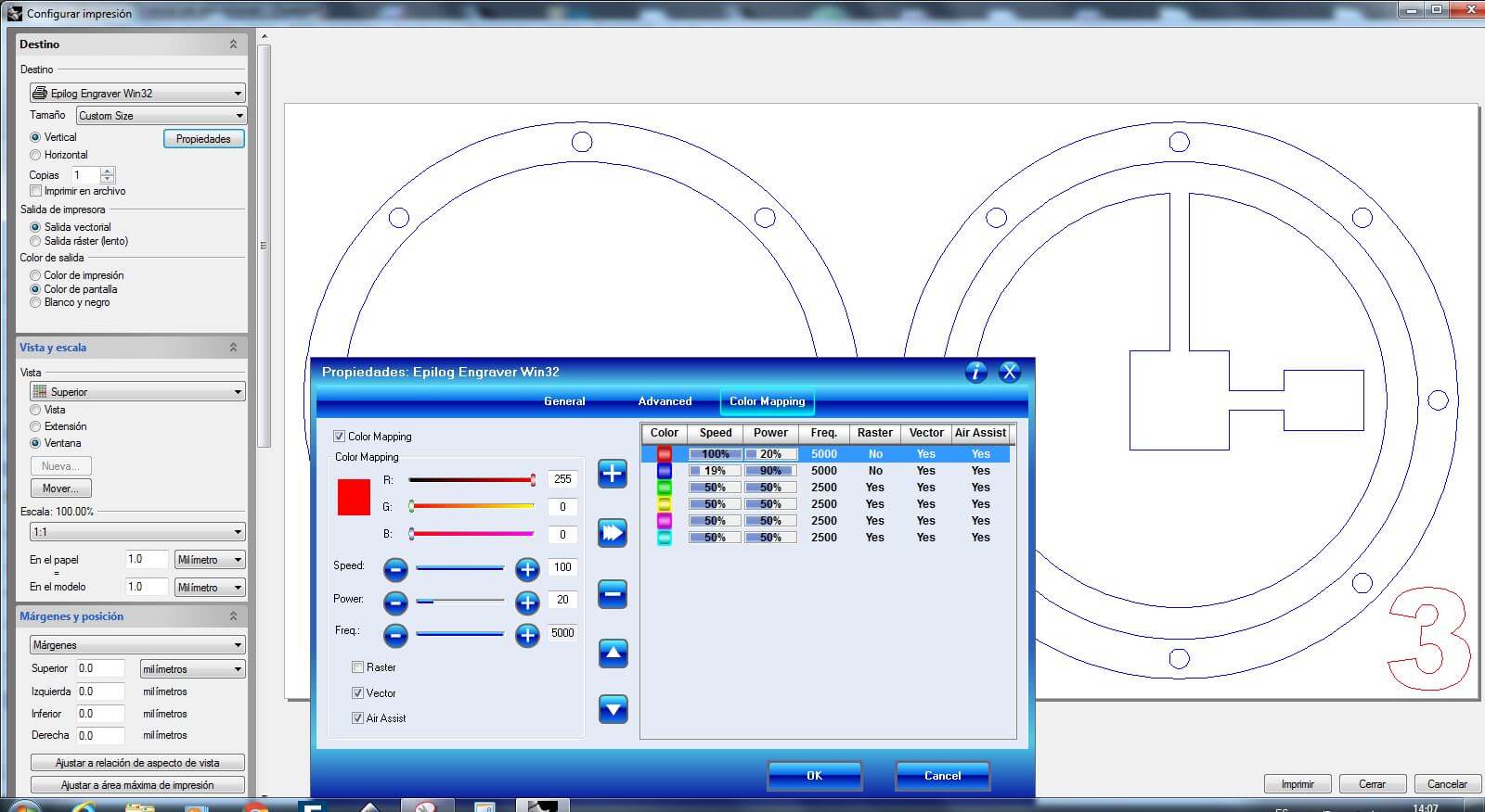
- Computer Controlled Cutting assignment: I will be using the laser cutterto make quick prototypes of the frame. Also to cut methacrylate for the watch faces.
- Electronics Production assignment: Fabricating the board it’s an essential for the project. Thankfully I’ve gained a lot of confidence with this process.
- 3D Scanning and Printing assignment: I’ll use 3D printing as the main tool for the system integration of the project. I’ll also try to use it as a watch face.
- 3D Electronics Design assignment: for designing the board for the project
- Computer Controlled Machining assignment: for machining the body of the project
- Embedded Programming assignment: for coding the software for the project
- Input Devices assignment: for the path to implement an input for the project
-
Output Devices assignment: for the use of the Oled and the path to implement an output for the project
-
Networking and Communications assignment: for the serial comunication for the bluetooth module in the project
- Interface and Application Programming assignment: for the smartphone app to use as interface with the project
-
Wildcard Week assignment: it has been the first approach to the physical form of the project itself. The idea of a sphere came from the concept of a clock, and the intention was to use a motor and a needle or representative element to visualise time on this surface. These are some of the results:
-
Applications and Implications assignment: it made me sumarize and specify all my project
- Invention, Intellectual Property and Business Models assignment: for specifying the license business model and future plan for my project
Prototyping⚓︎
Looking back, I would have liked to have had the project more defined from the beginning of the course, because it would have allowed me to have researched all the work that I now have ahead of me, especially because I will not be able to reach the level of knowledge I would like of each of the processes or devices. This has a negative impact on the project because it will not allow me to refine it as much as I would like, but this is a learning process.
Translucent wood⚓︎
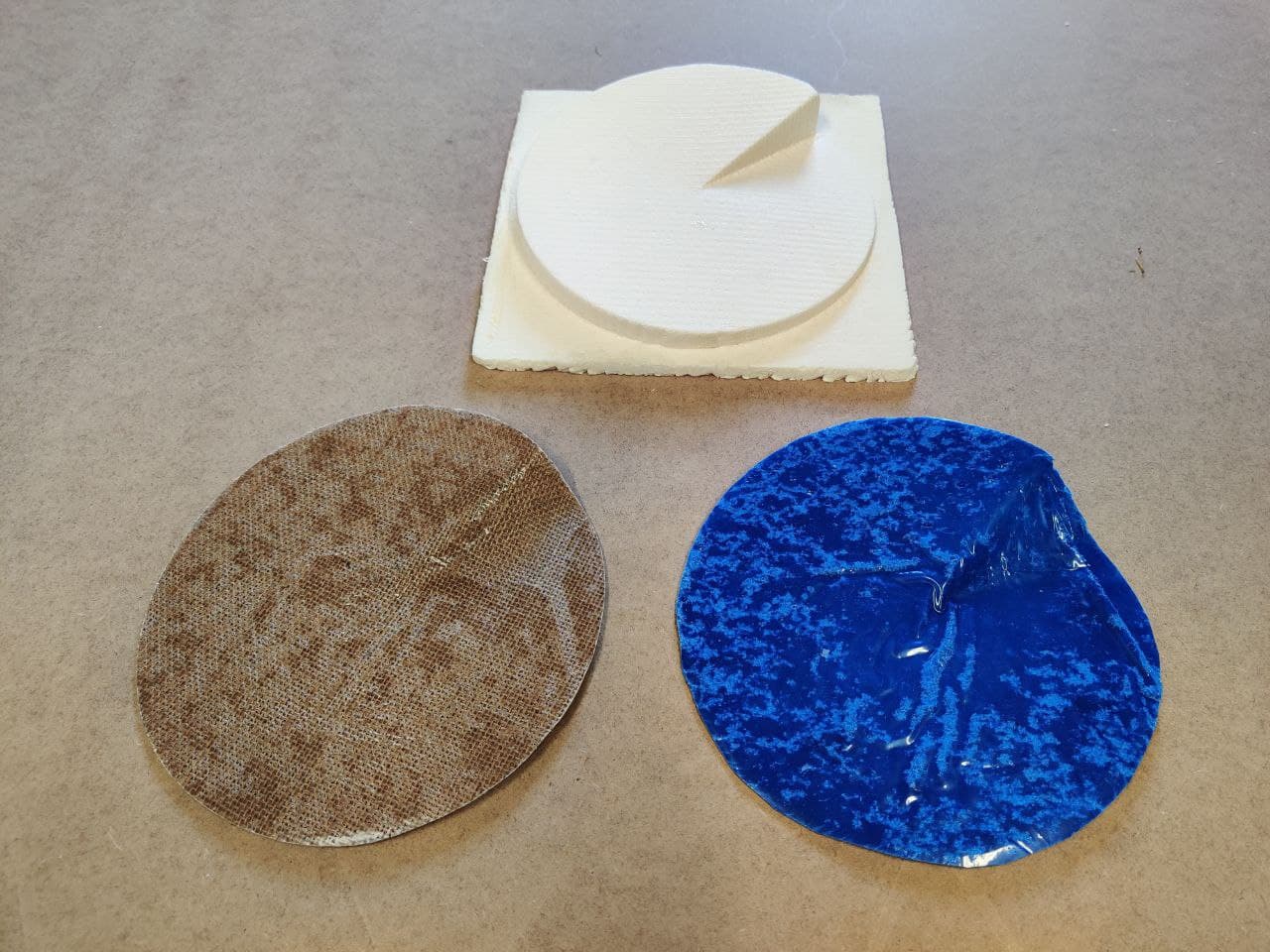
Quick prototyping for making a model with different depths to test translucency. The model it’s a cilinder split in two, with one half to put the corresponding LEDs to try and the other with the depths samples.
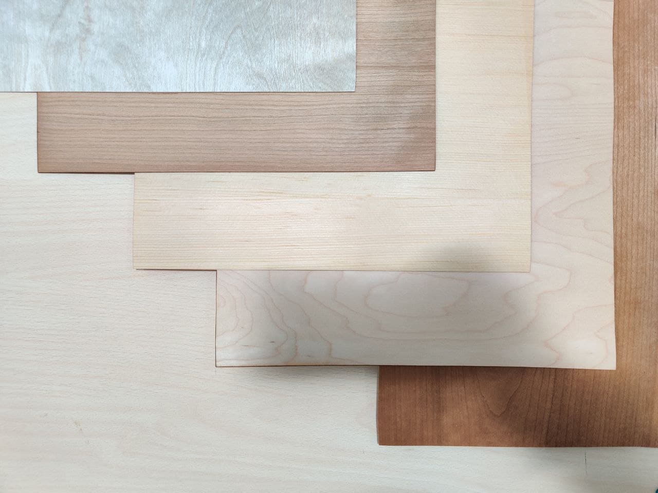
I’ve made coupons with three different type of wood and depths. Depths vary from 0‘2mm to 1‘2mm with 0‘2mm of difference between each one. Wood types are, from left to right on the following images:
- 18mm poplar plywood
- 9mm birch plywood
- 16mm slatted pine
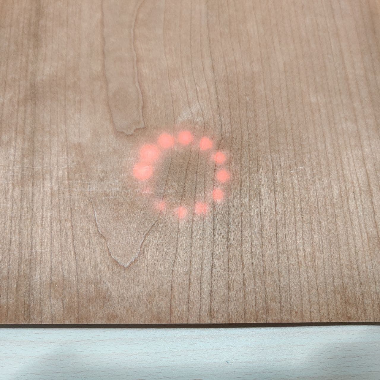
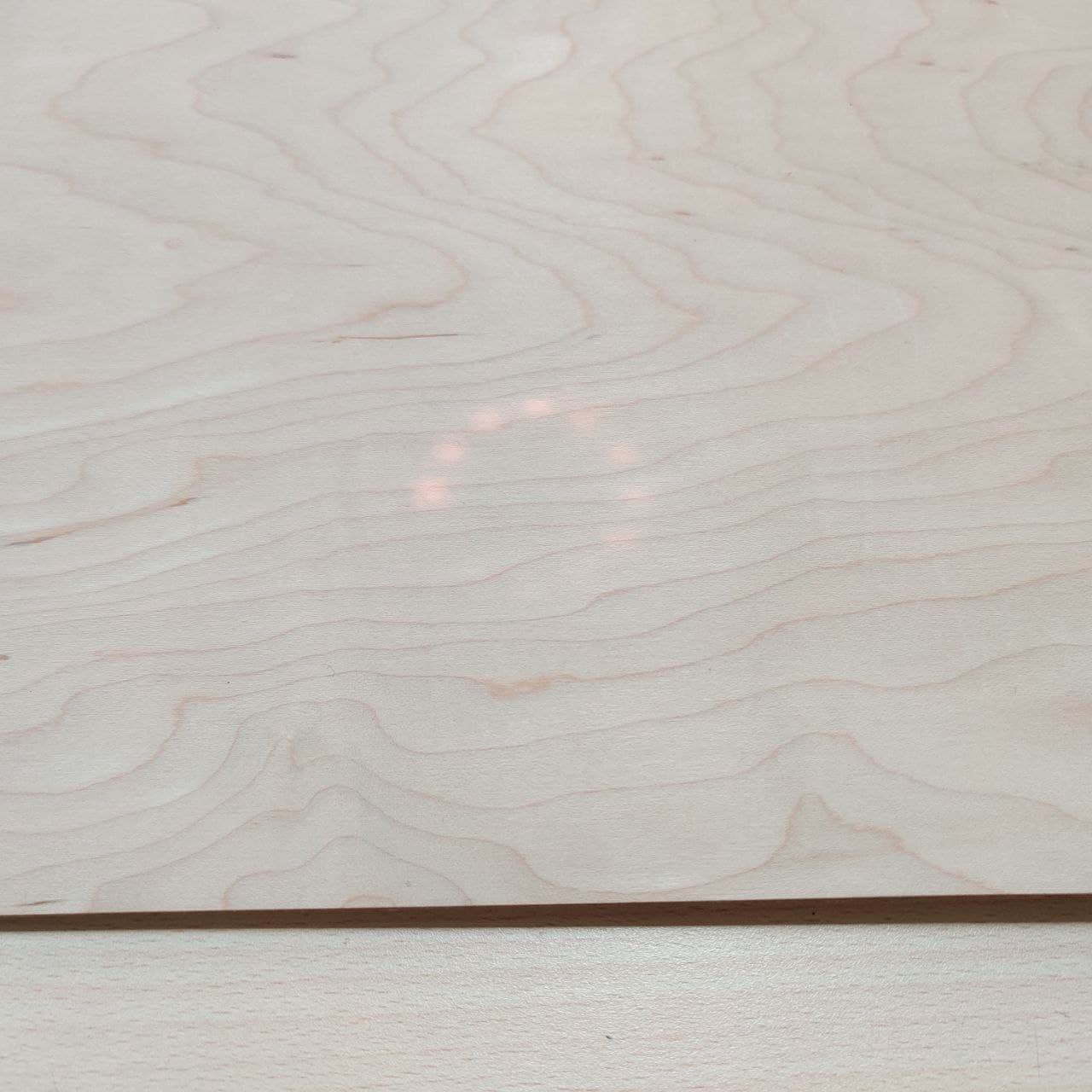
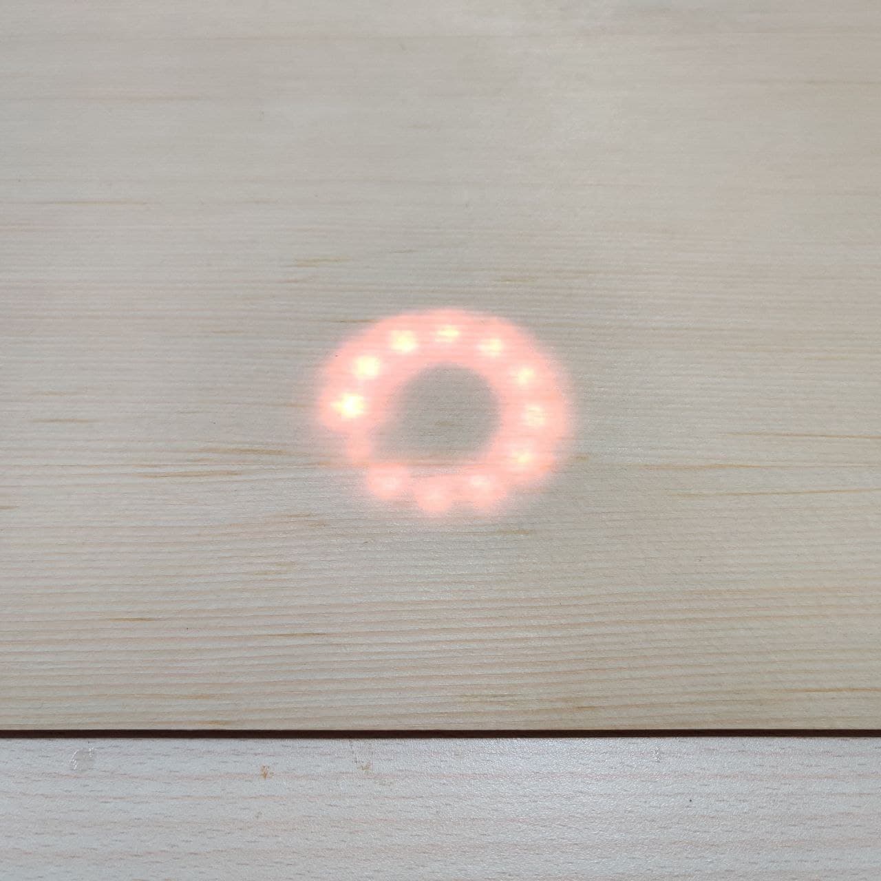
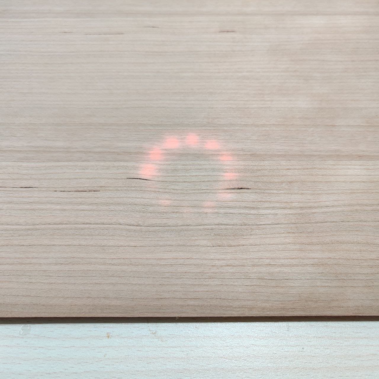
First try is with the LED strip with the LEDs facing sideways to give a more blurred effect.
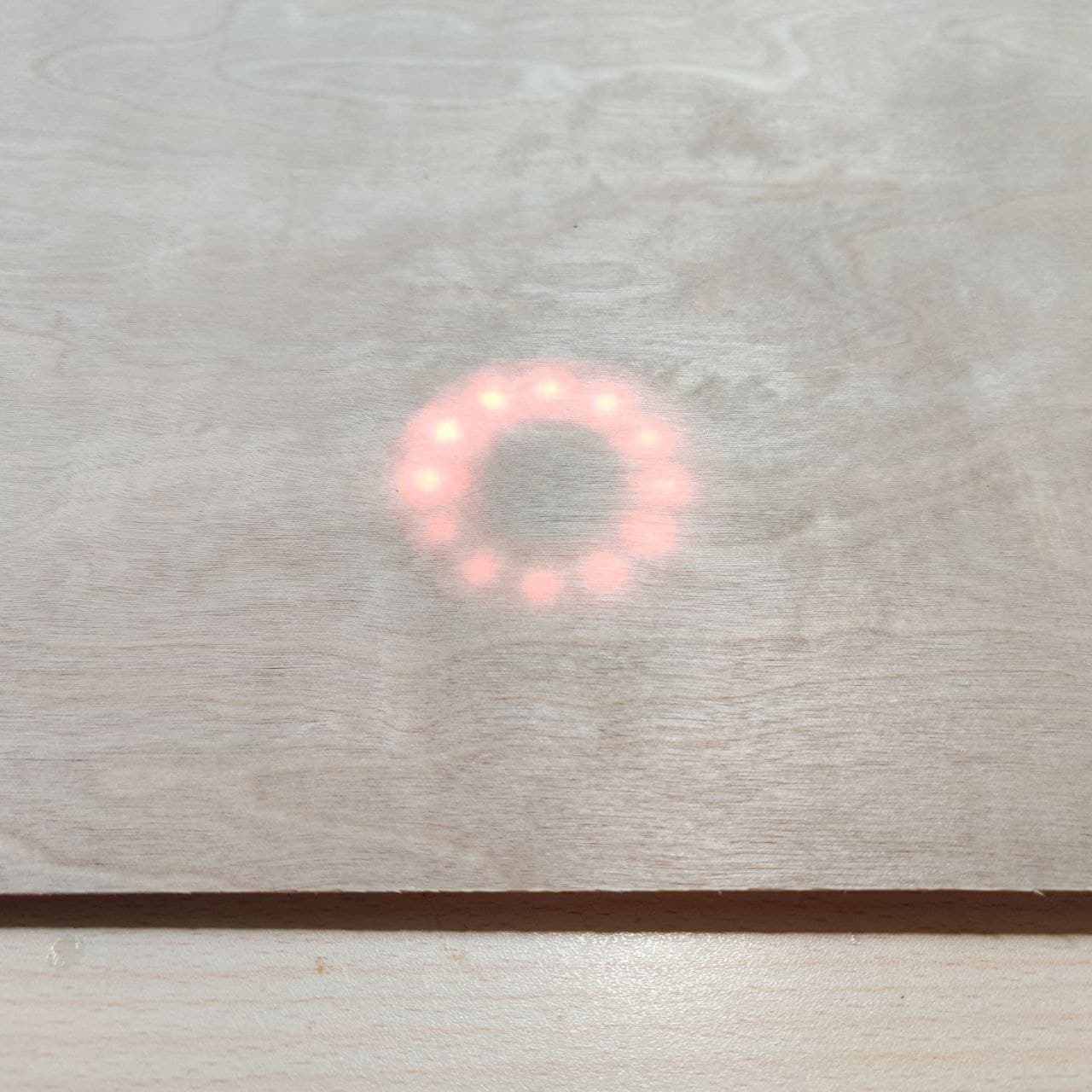
Second try is with the LED ring which has the LEDs facing upwards. This provides more brightness to the light but LEDs are distinguishable.
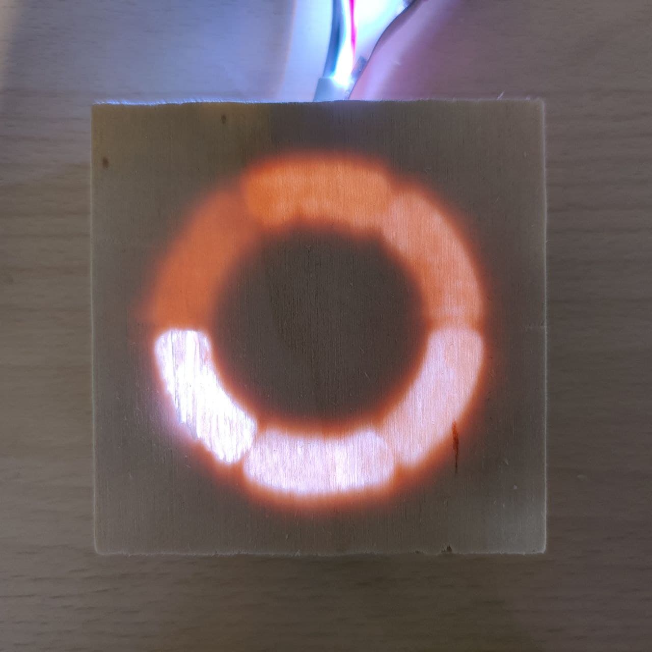
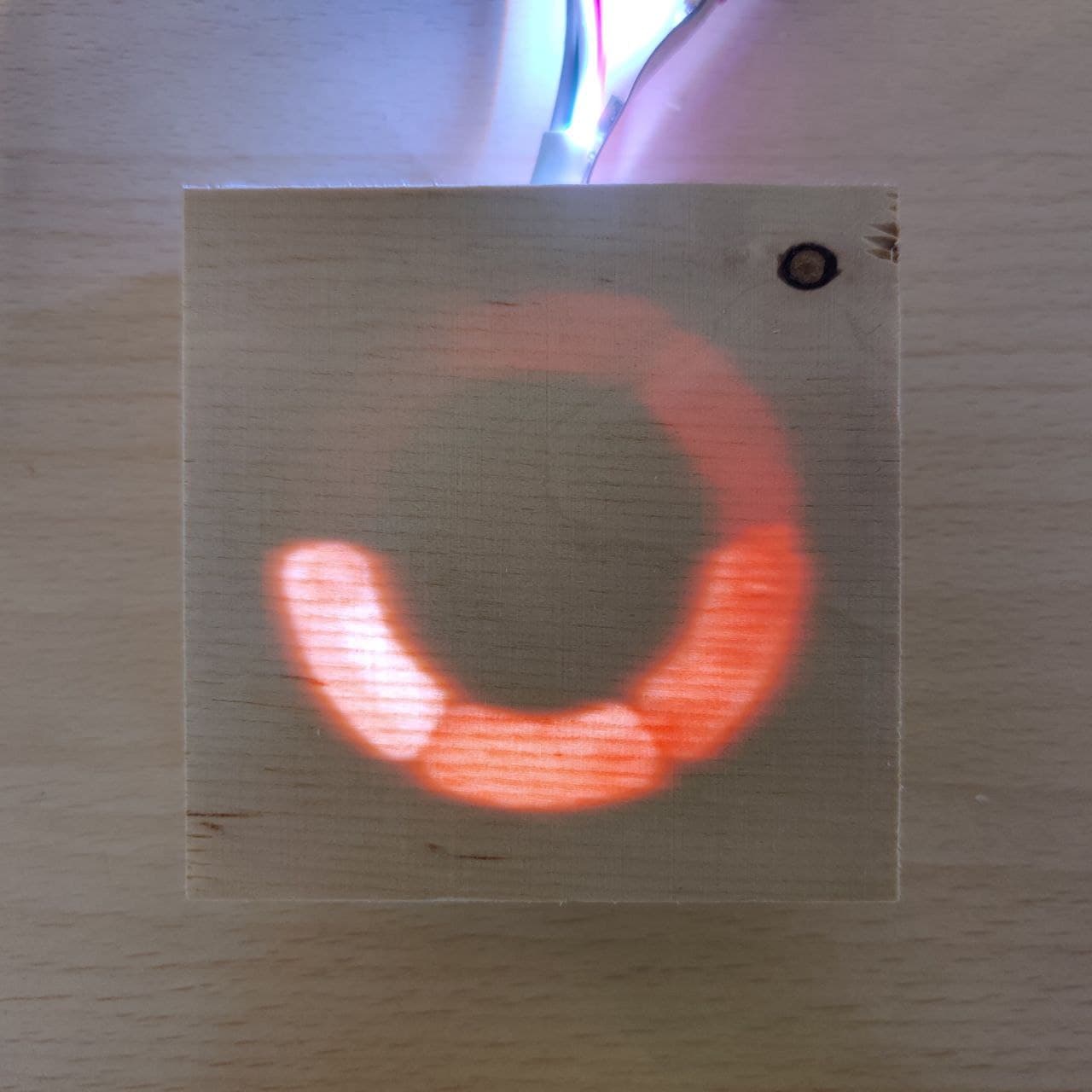
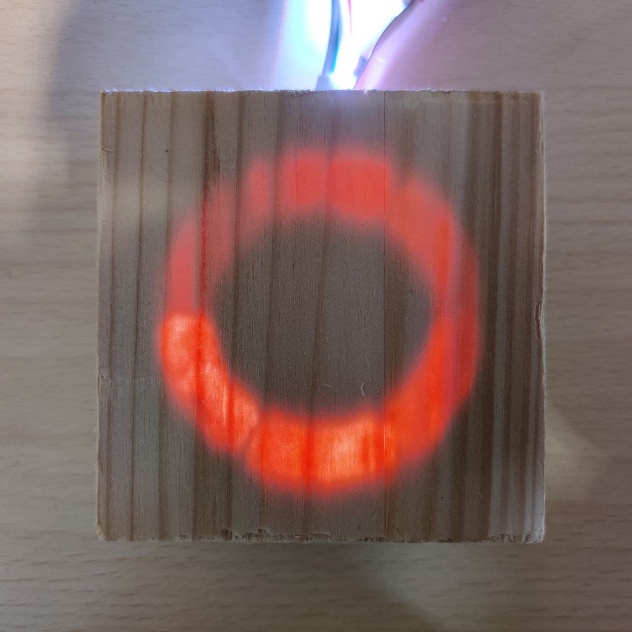
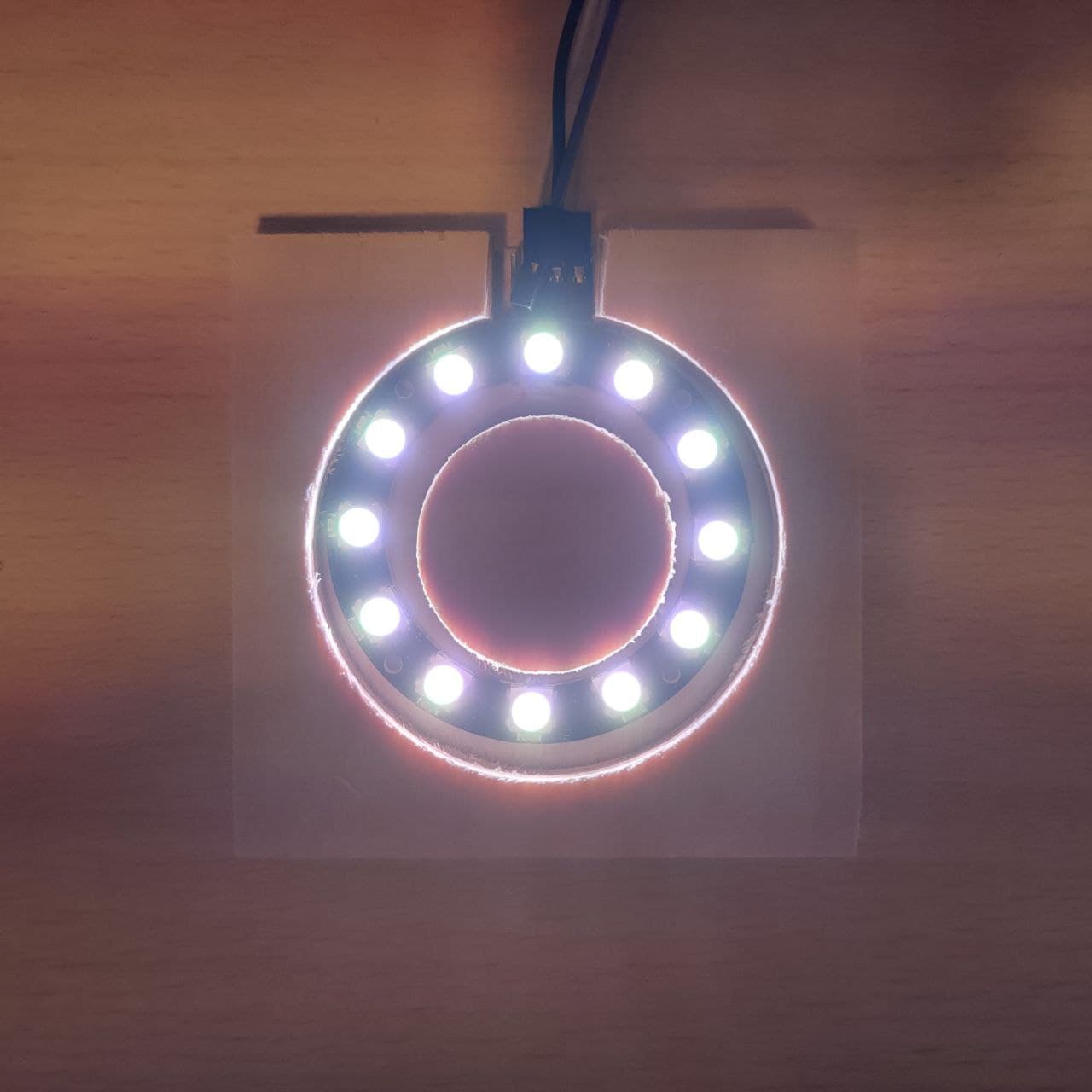
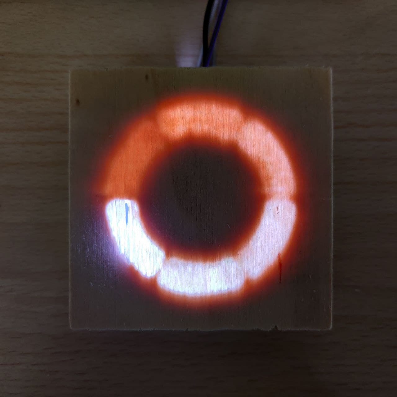
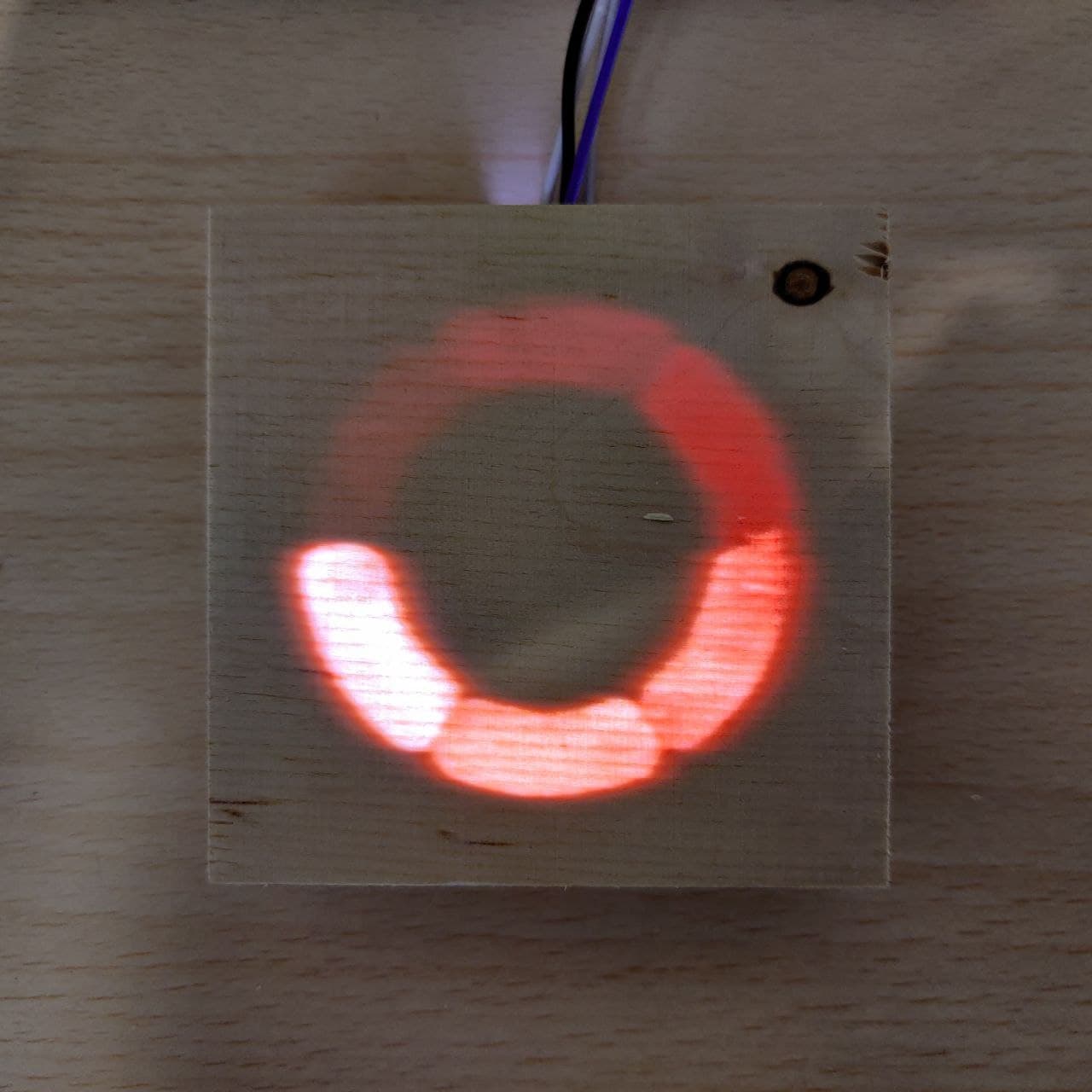
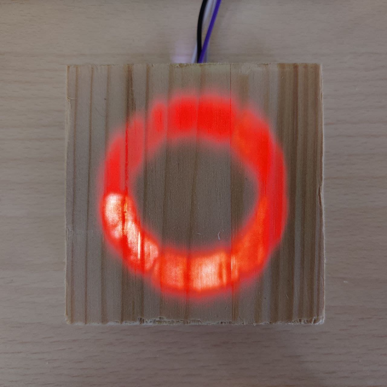
Conclusion: I want more density of leds per meter, to have a more uniform lighting. Also I prefered direct light but making a ring as big as 1 meter of circunference would make it pretty hard, so I would probably stick with the led strip type.
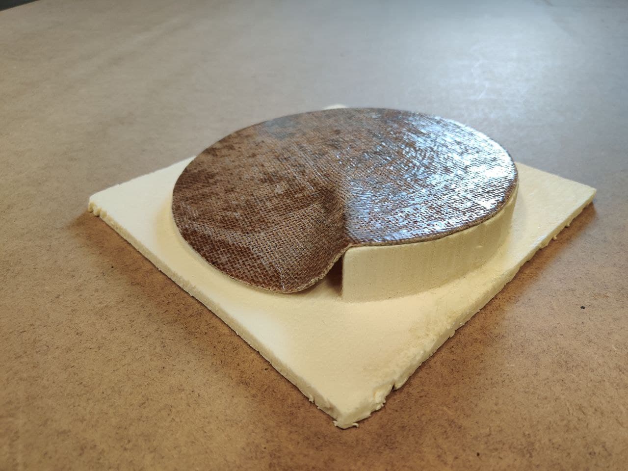
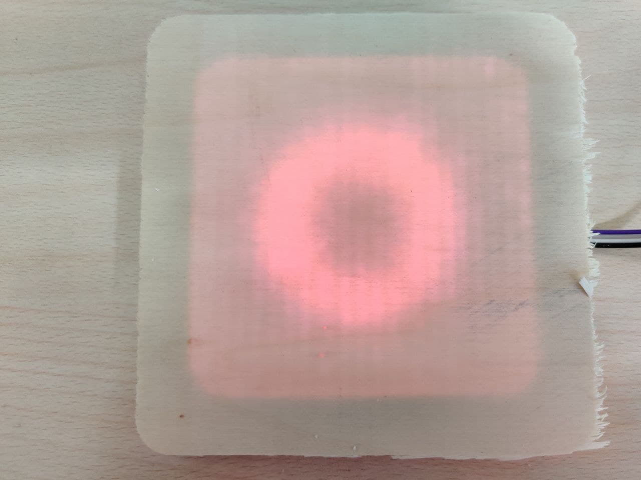
This tests with bigger surface are made on the 18mm poplar plywood with 0‘6mm depth.
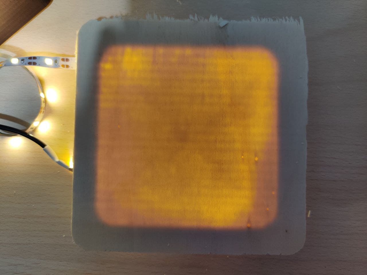
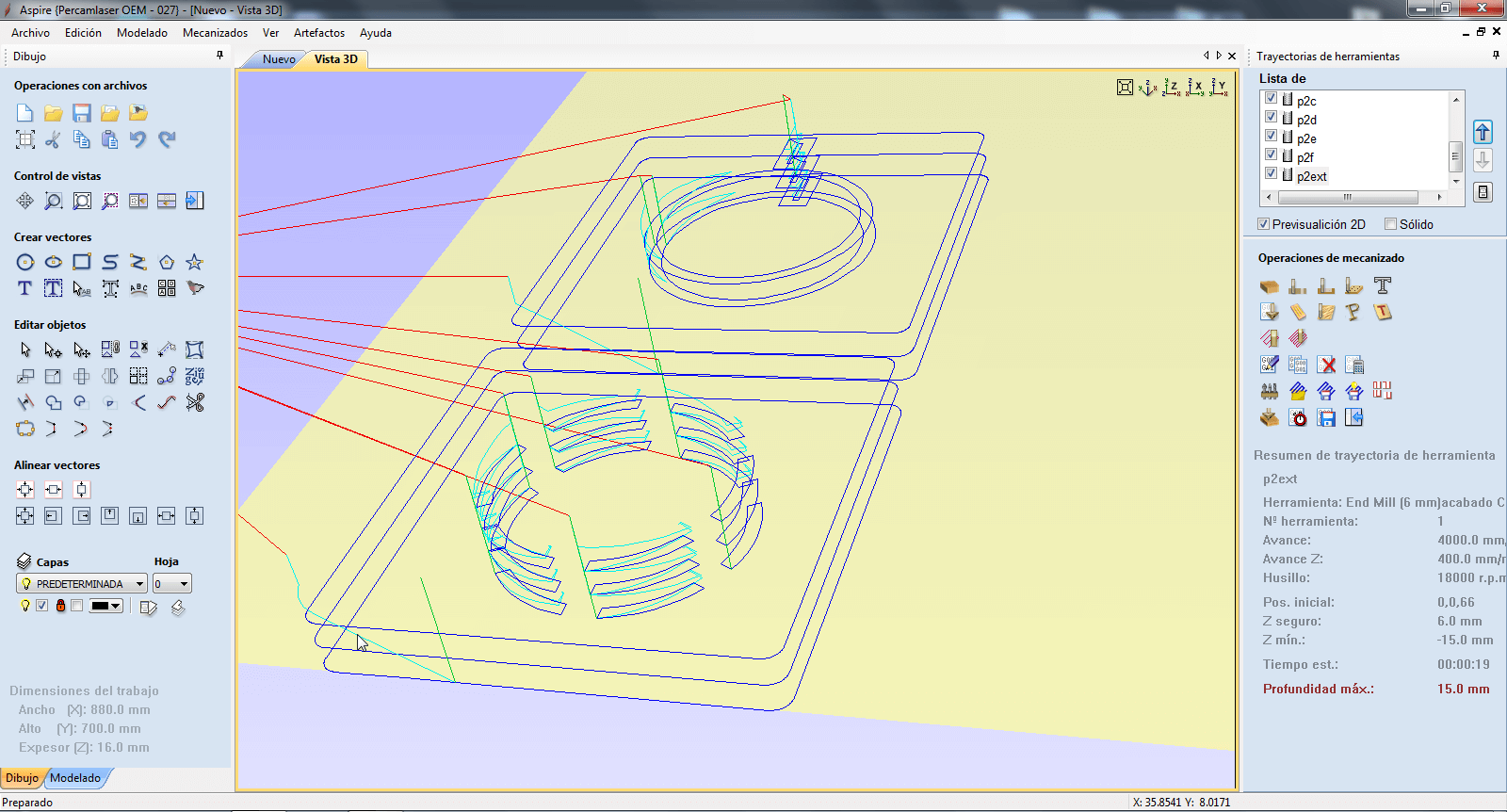
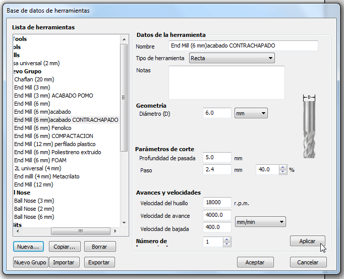
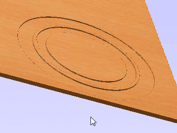
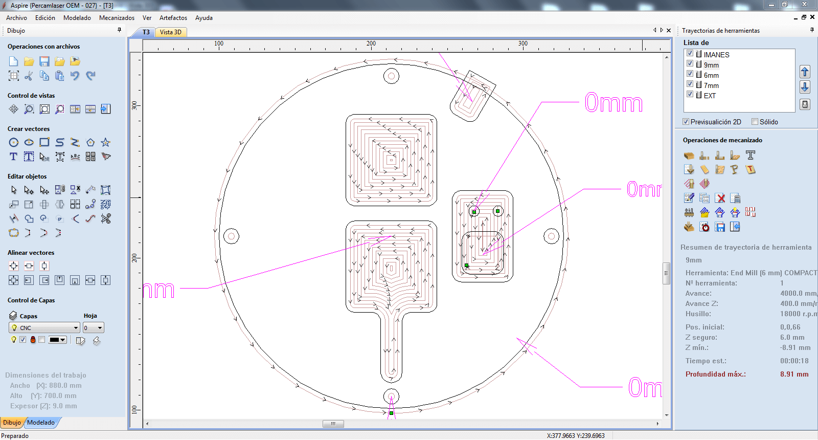
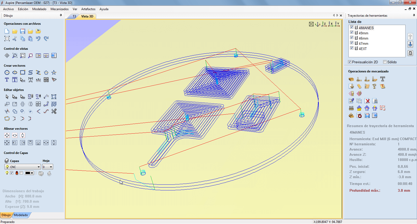
Tried making the clock sphere to test milling this thin on a bigger surface. Had some issues because of how Aspire handles the milling. It creates two paths, one that mills from the centre to the outer edge, and then another that mills from the inner edge to the centre of the lathe. The problem occurs when milling the last layer, when the height is minimal and the material is not able to withstand the drag of the milling cutter, tearing the laminate.
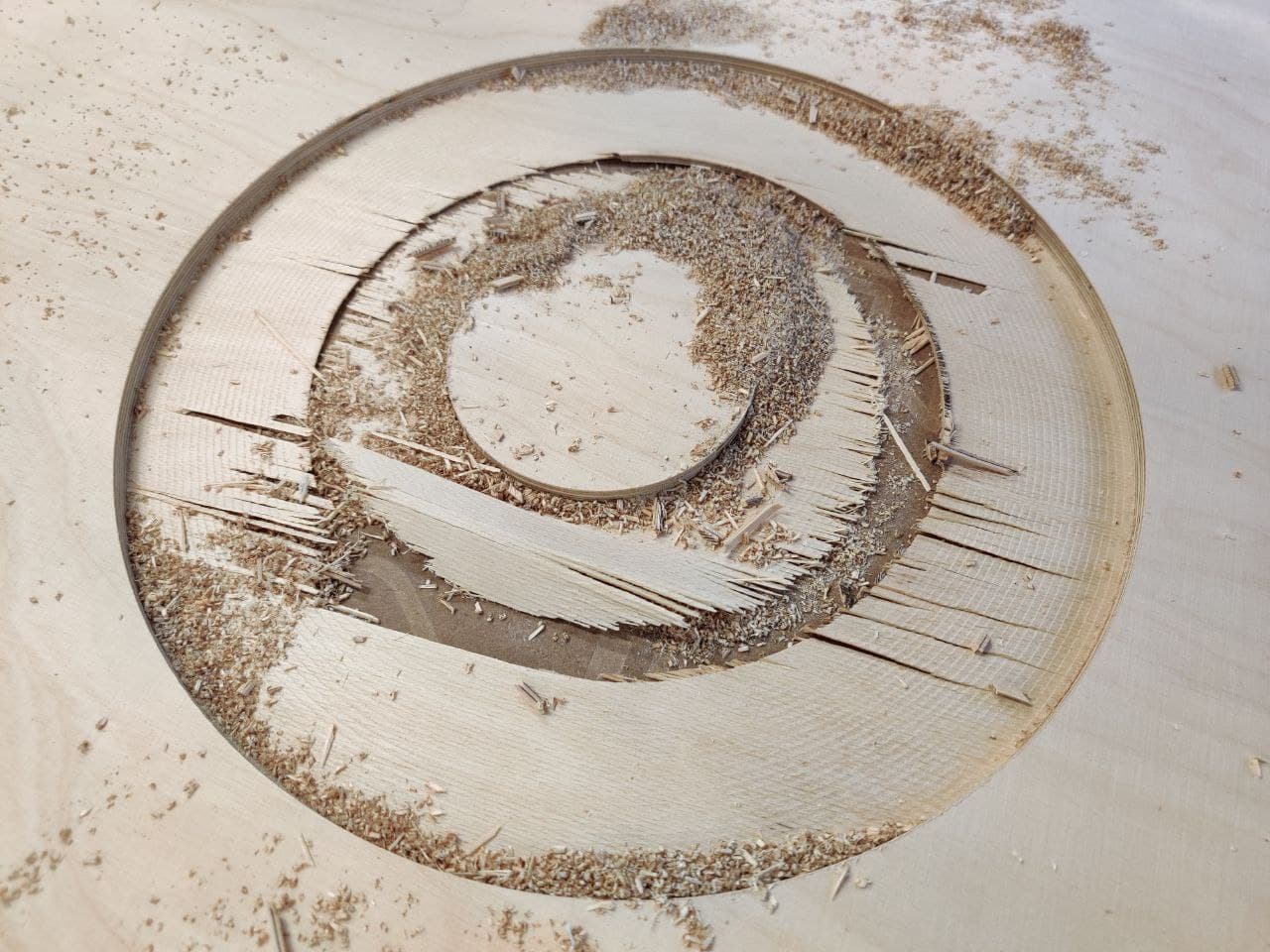
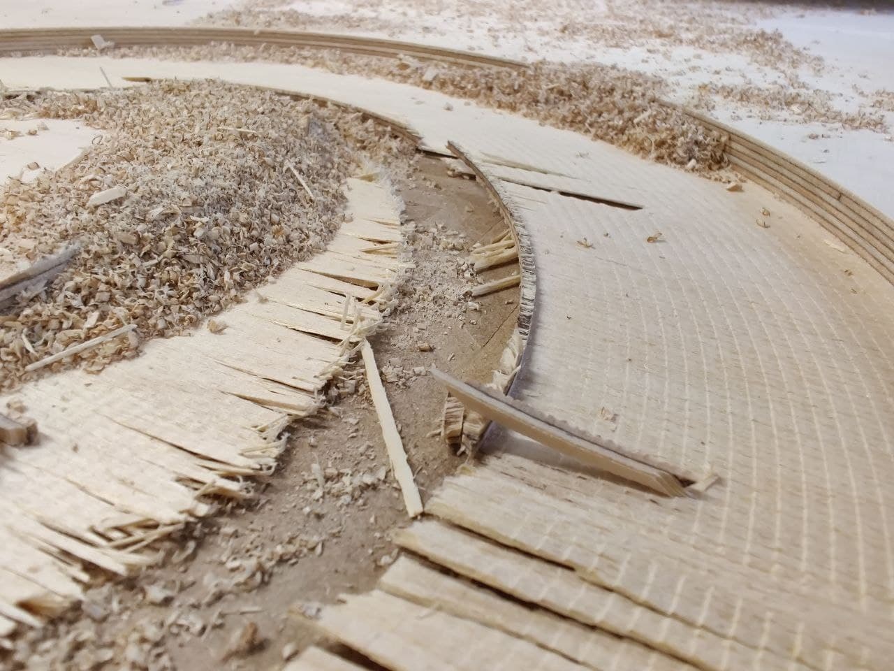
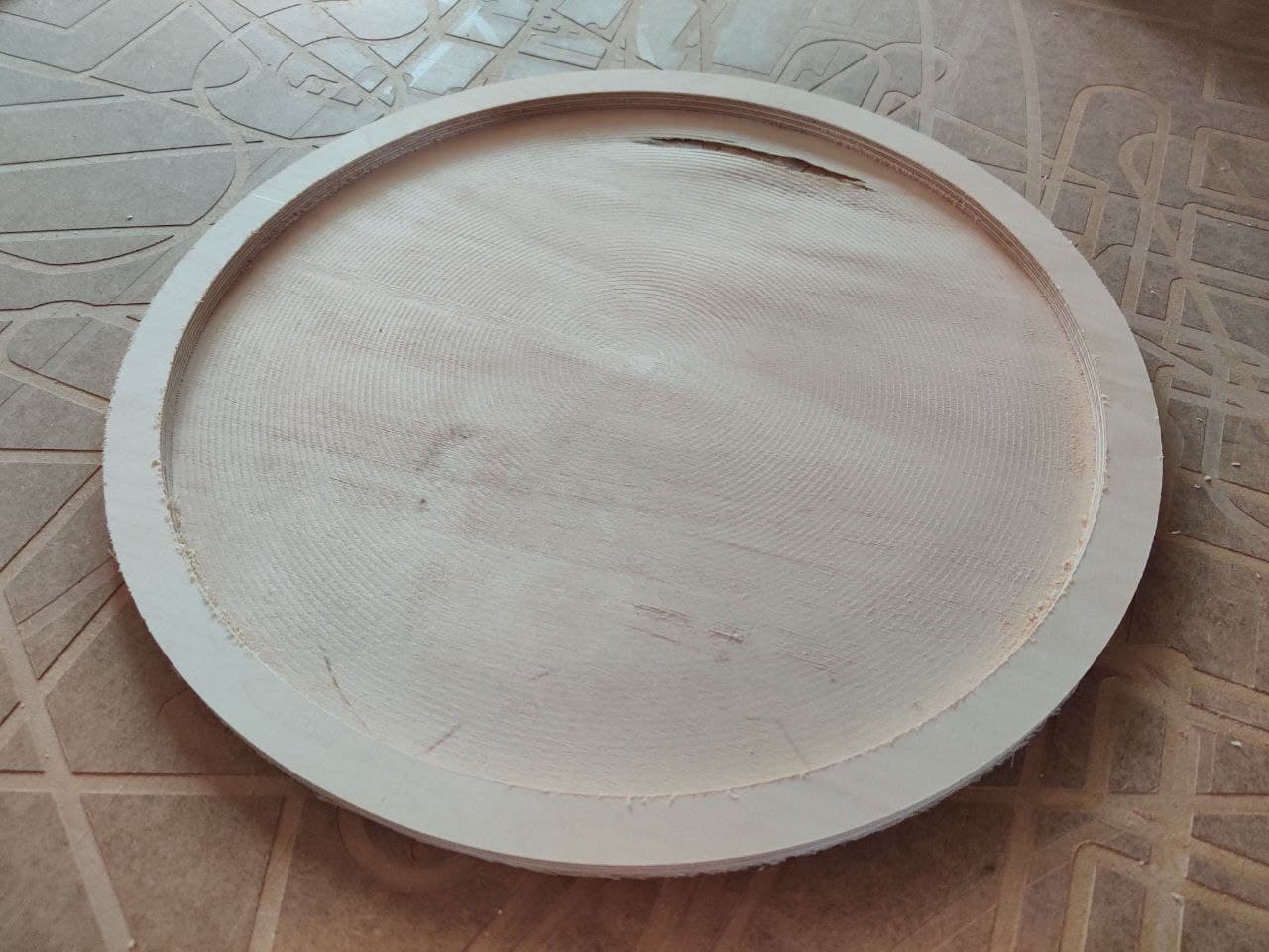
After carefully checking the file and the vectors in case there was any design error, it is not the case, so the only solution is to mill it without the central circle. The result has been good, but as I did the test quickly, without readjusting z since the last milling and the martyr is not planned, one area has been thicker than the other. The model is valid for the first prototypes, and adjusting correctly the Z axis I think I could get a satisfactory final result.
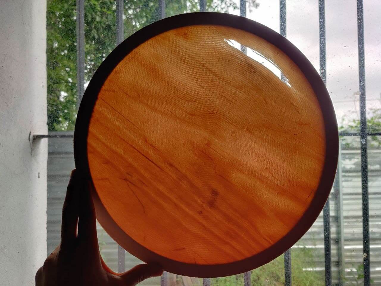
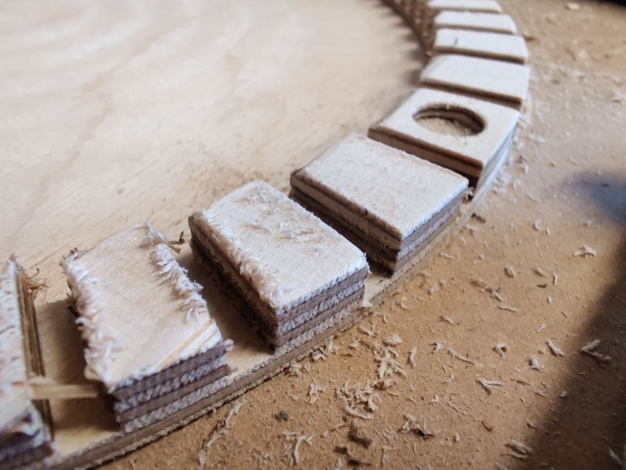
Another option that I have considered is to use these wooden sheets as a translucent sheet, since they can be cut directly on the laser cutter and adaptation to the design would be very simple. In addition, the finish is very beautiful and allows much more variety.
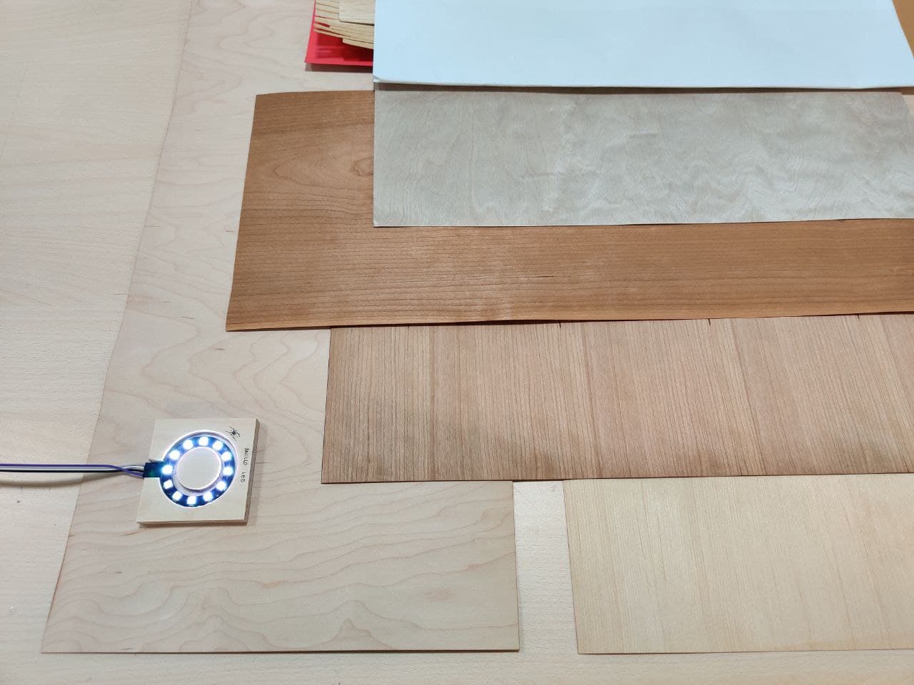
From bottom to top (right picture below), these laminates of wood are:
- Cherry veneer
- Double-sided beech laminate
- Single-sided beech laminate
- Single-sided cherry laminate
- Birch plywood
Body for the project⚓︎
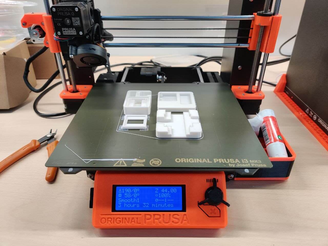
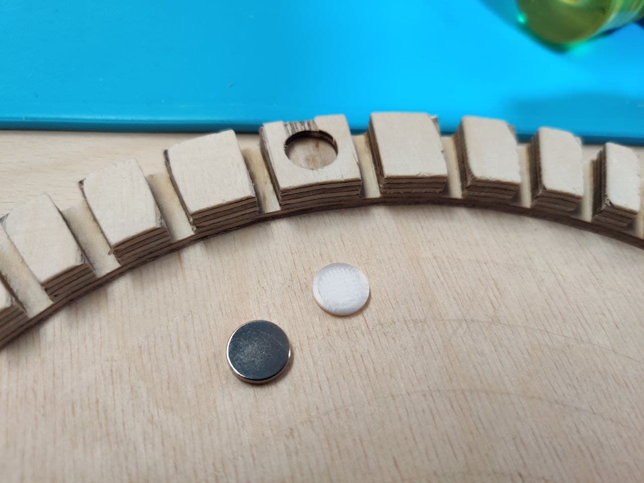
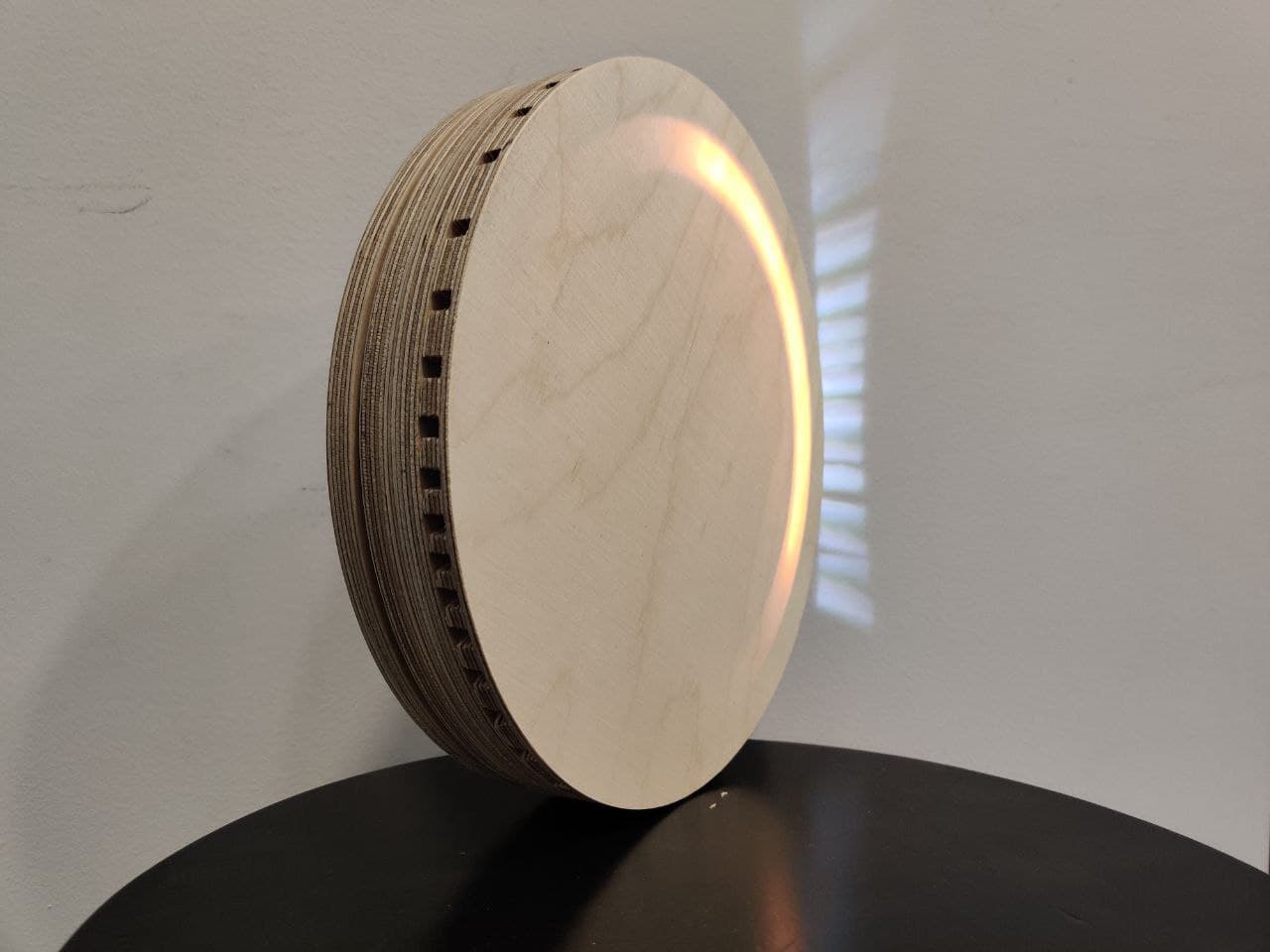
To make a first working prototype, Nuria suggested to make the body of the project in 3mm DM. As my design will be made in 4 9mm wood pieces, the design can be splitted in 12 layers of 3 mm DM.
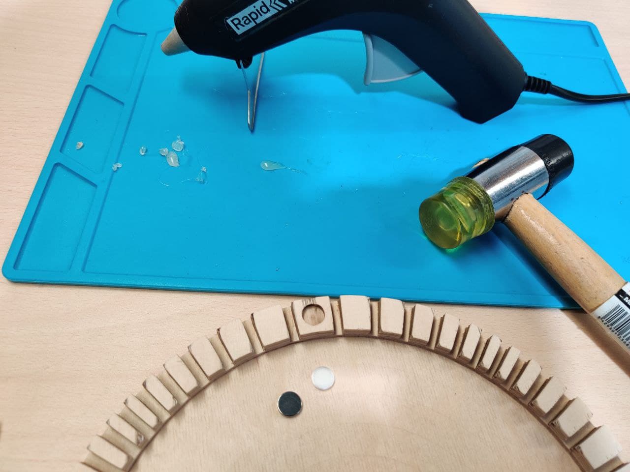
Once I had all the parts, I glue the ones that come together to make the 9mm solid parts and left the ones that attach with magnets. I’ve also cutted a thin layer of paper wood for the translucent part.
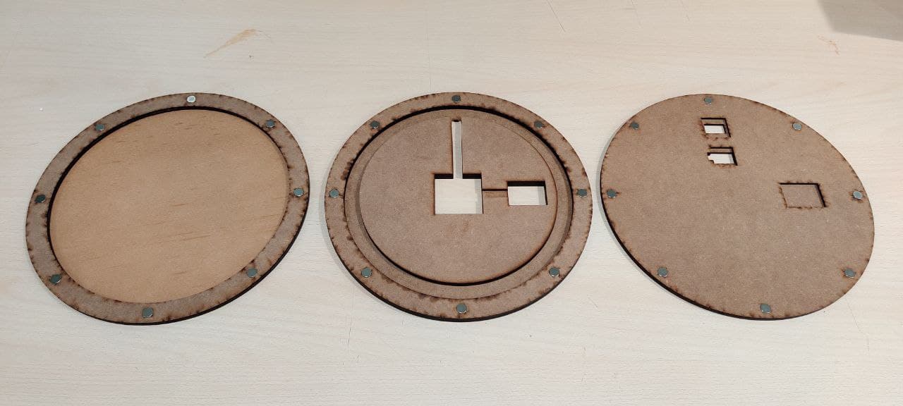
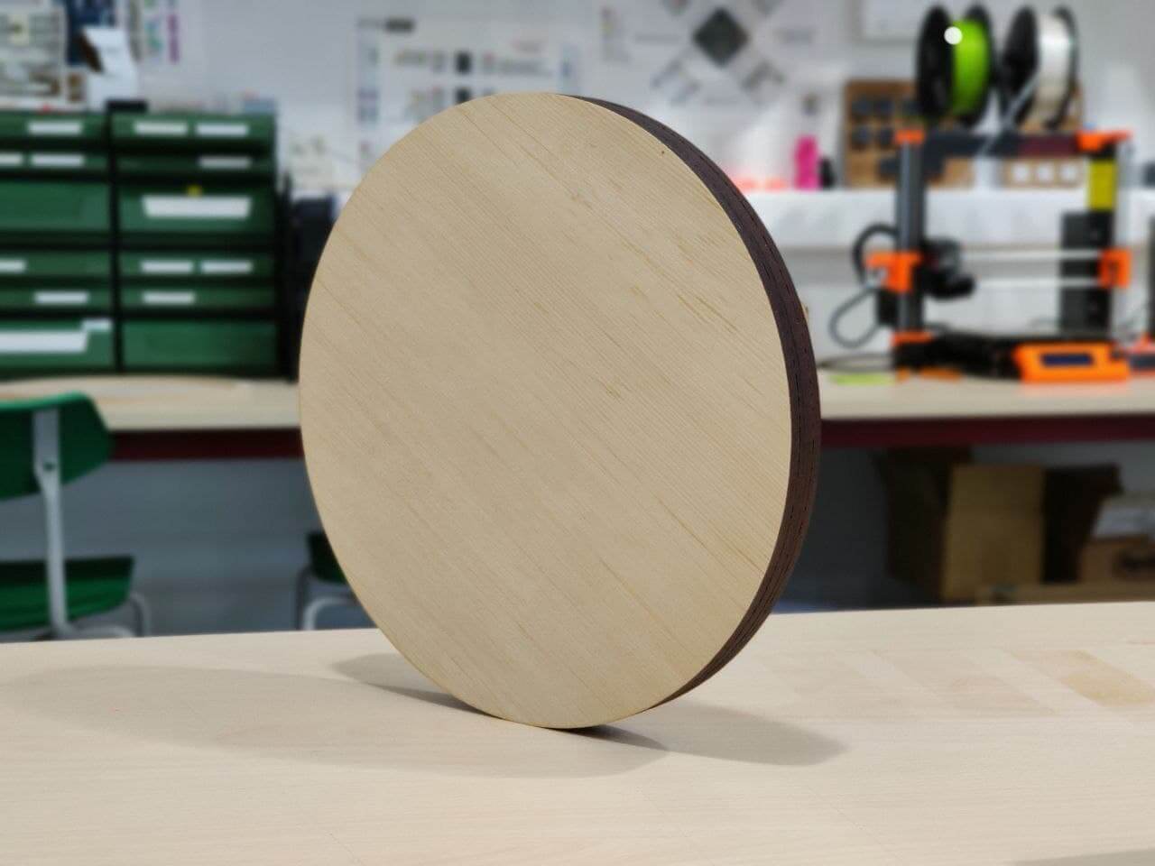
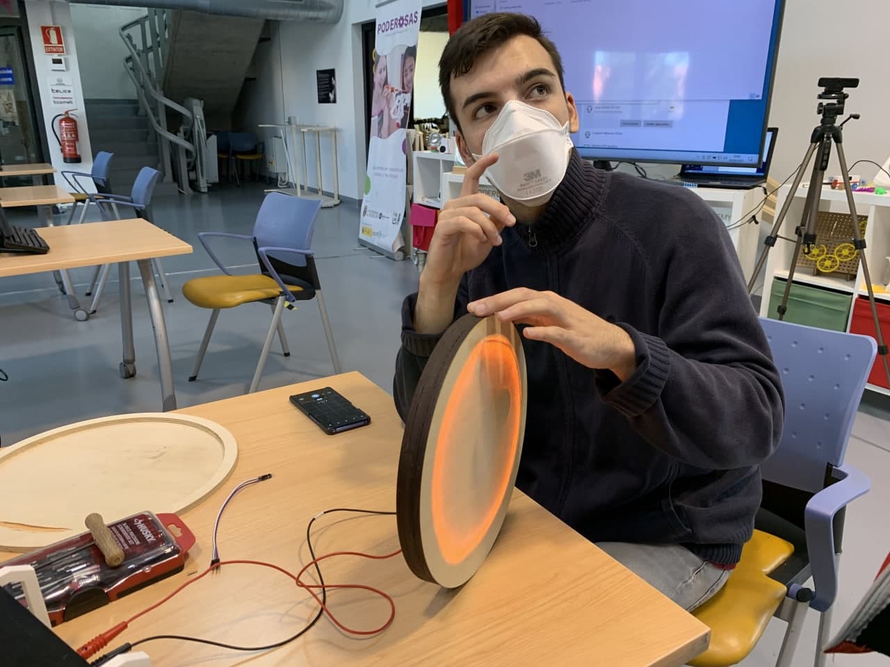
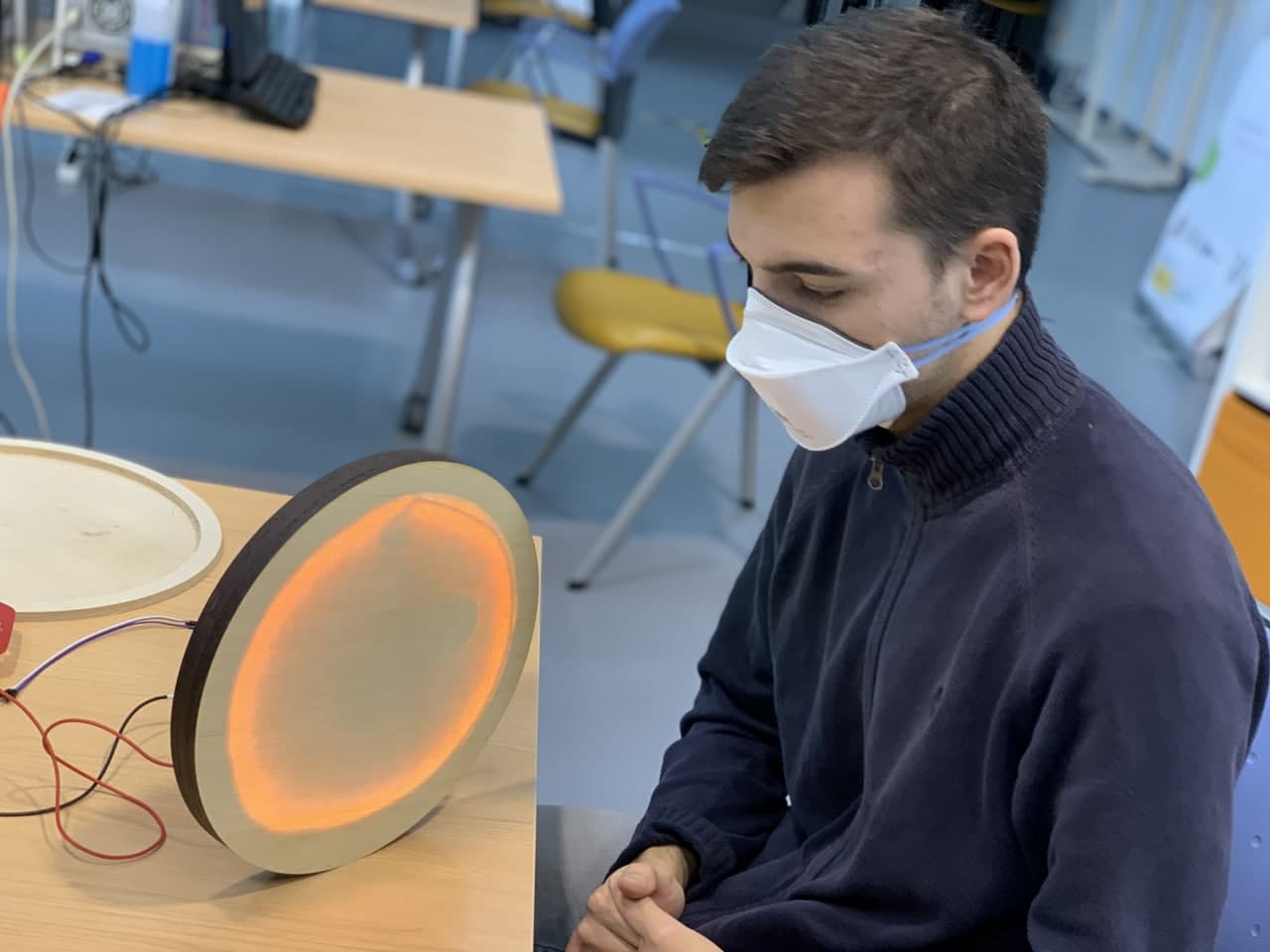
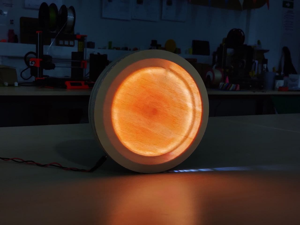
Besides being a protoype, it looks very good
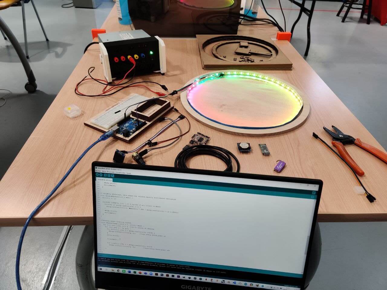
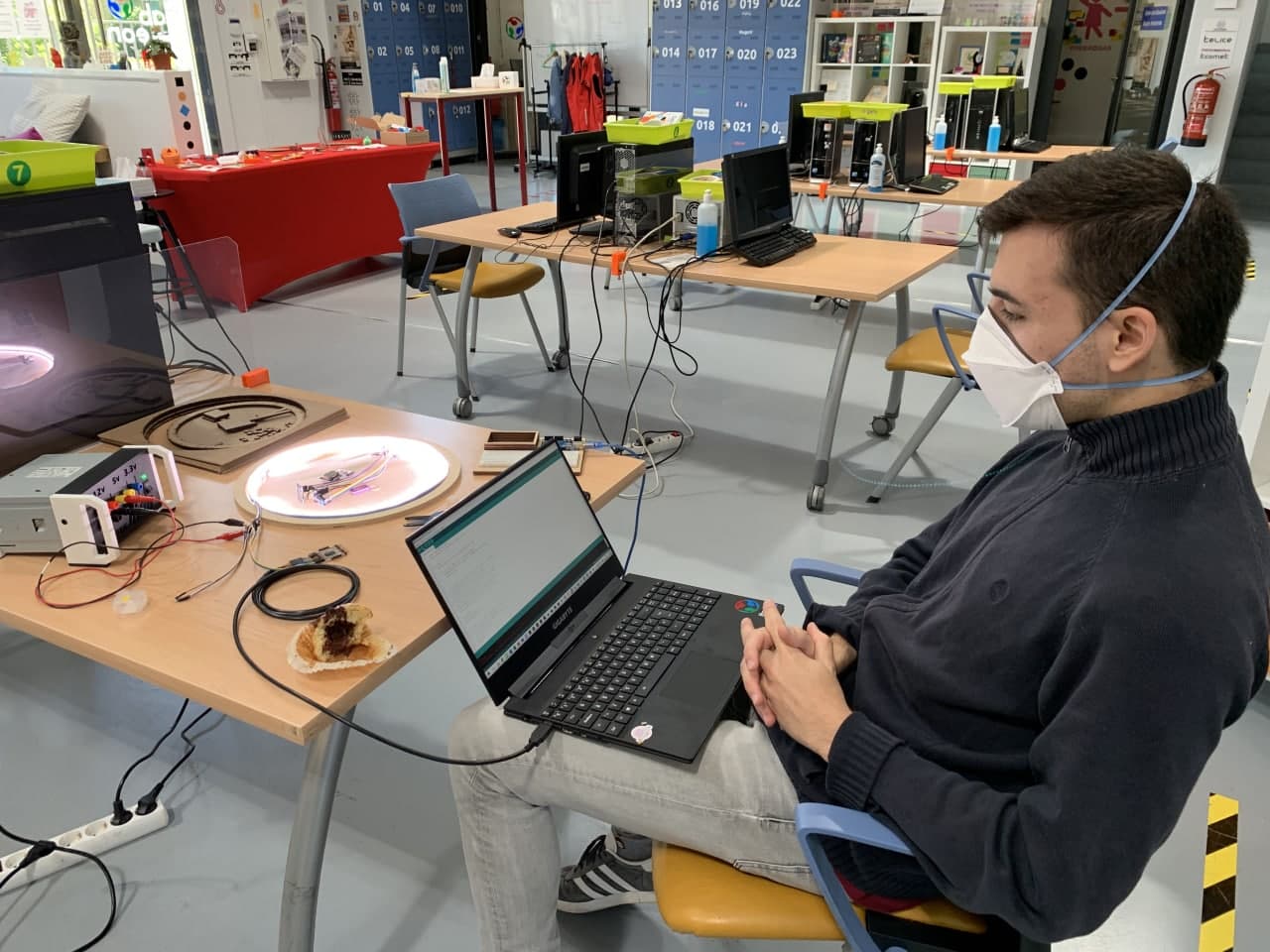
Testing⚓︎
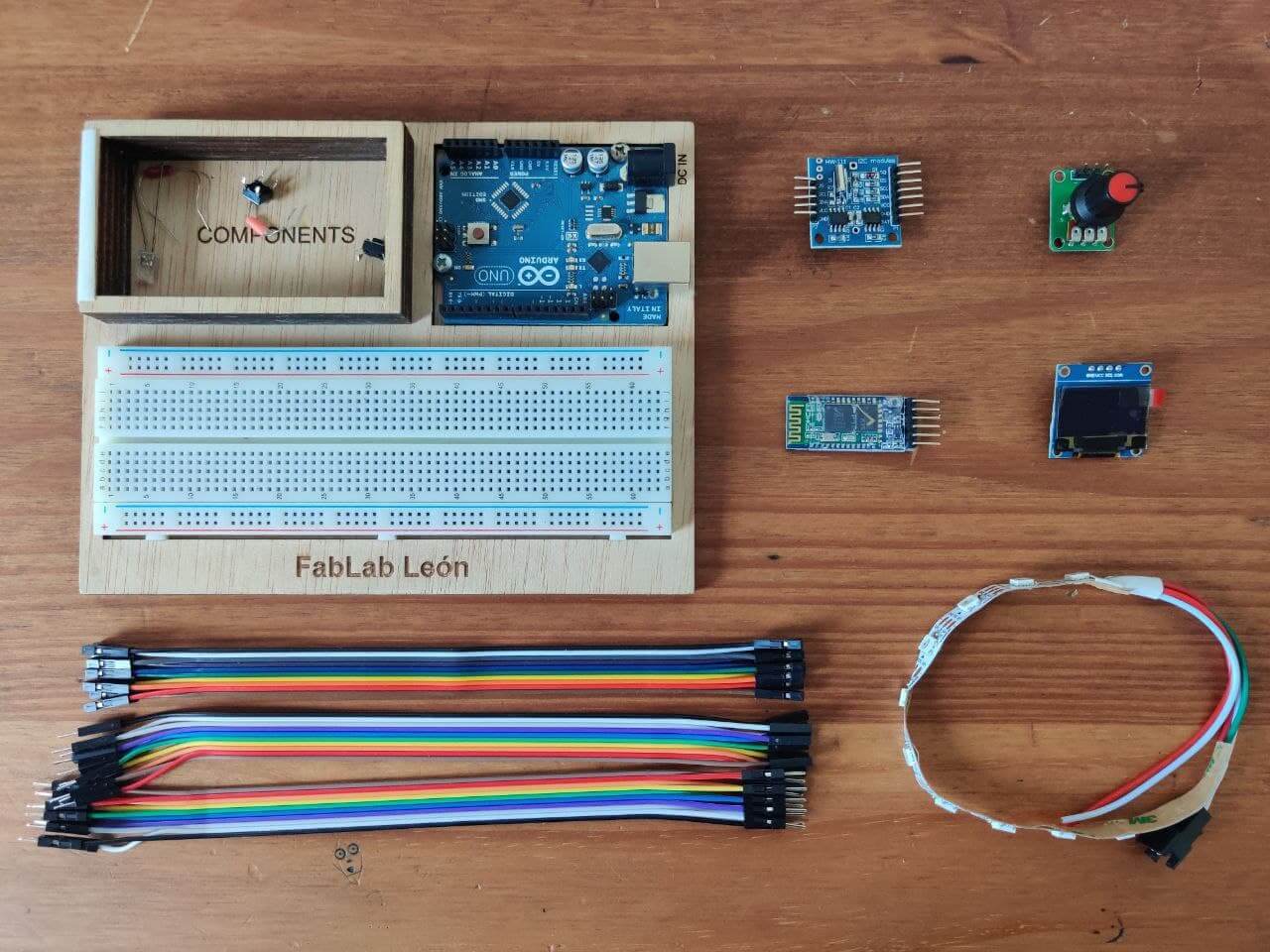
For this first prototyping spiral I am going to use an arduino uno together with a breadboard to assemble the electronics of the project. With this I intend to speed up the process of writing the code and achieve a first viable prototype. In my case, seeing the project materialize will encourage me to enter an upward spiral of work, because otherwise it is very difficult for me to capture the work or the entire mental flow. These are the main components that I am going to use:
- RTC: to check the time and make the timer precise
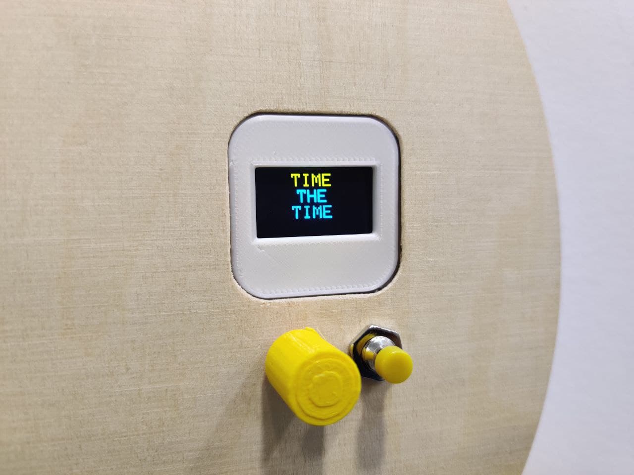
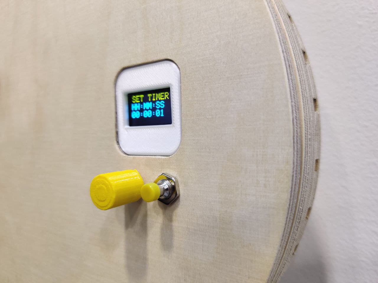
- OLED: as interface for the user to choose the desired parameters
- Potentiometer: dial to select the time
- Neopixels: to visualize the time percentaje
- Bluetooth module: to connect to the phone and use that interface
RTC⚓︎
-
HARDWARE:
- Using an Arduino UNO as a test board and a breadboard with jumpers. We connect the Arduino to the PC, open Arduino and select it from
Tools>Board>Arduino UNO Port: the port that appears to us as the Arduino connected, in my caseCOM3- Concect SCL(RTC) to A5(UNO) and SDA(RTC) to A4(UNO), GND to GND and VCC to VCC
- Using an Arduino UNO as a test board and a breadboard with jumpers. We connect the Arduino to the PC, open Arduino and select it from
-
SOFTWARE:
- We open Arduino, we download the Mickael Margolis DS1307RTC library from the library manager:
Program>Include libraries>Manage libraries. We download TimeLib from here and add it to Arduino:Program>Include libraries>Add .ZIP library - We load the example to set the RTC time:
File>Examples>DS1307RTC>SetTimeand we upload it. Uses the PC time to configure the RTC time (hence the variables__DATE__and__TIME__) -
To check if it has worked, we load the example to set the RTC time:
File>Examples>DS1307RTC>ReadTestand we upload it. We open the serial monitor to read the RTC data.
- We open Arduino, we download the Mickael Margolis DS1307RTC library from the library manager:
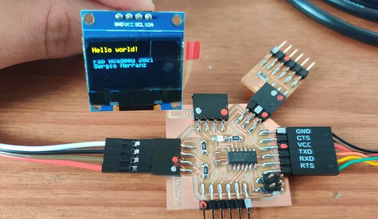
I’ve used this tutorial to display the time from the RTC to the Oled using the Arduino

Neopixels⚓︎
I’ve made a TinkerCad projecto to learn the basics about neopixels coding and wiring.
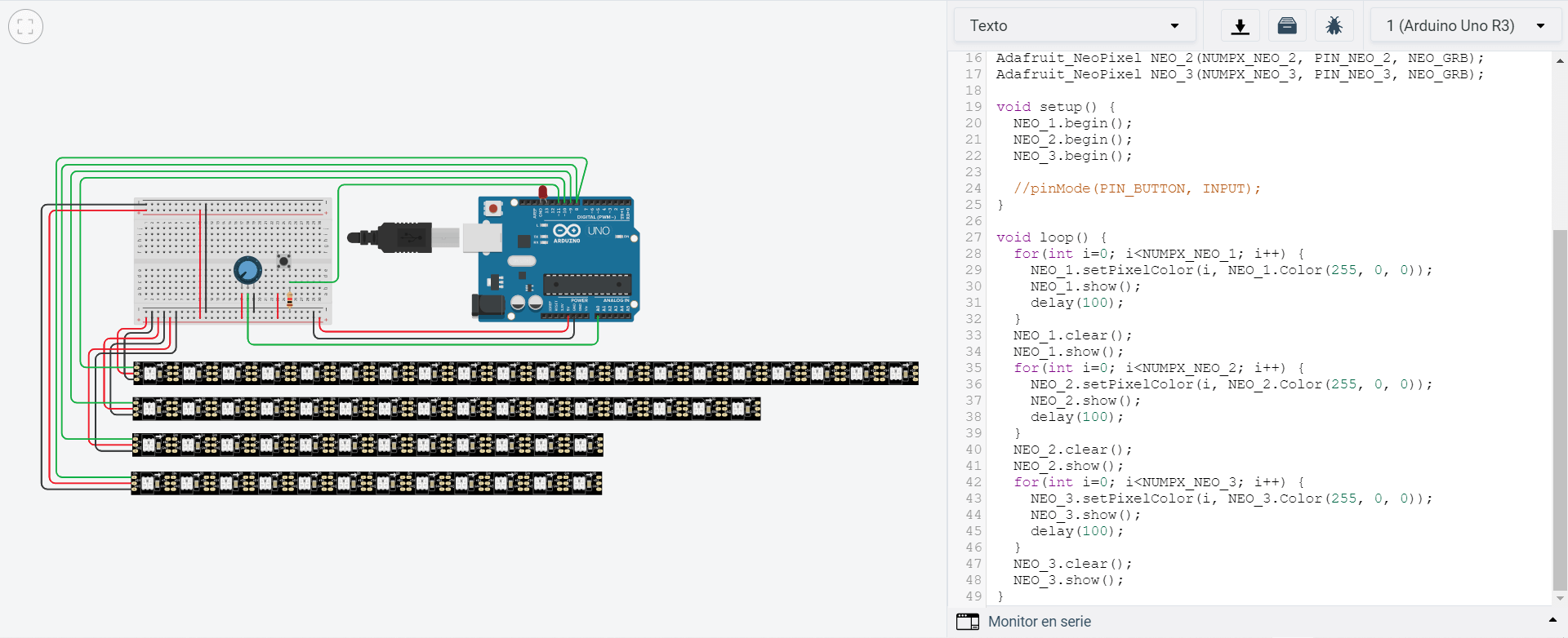
Test the neopixels with the Arduino UNO.
Using a 4 meter ws2812b neopixel strip with 60 leds/m for testing.
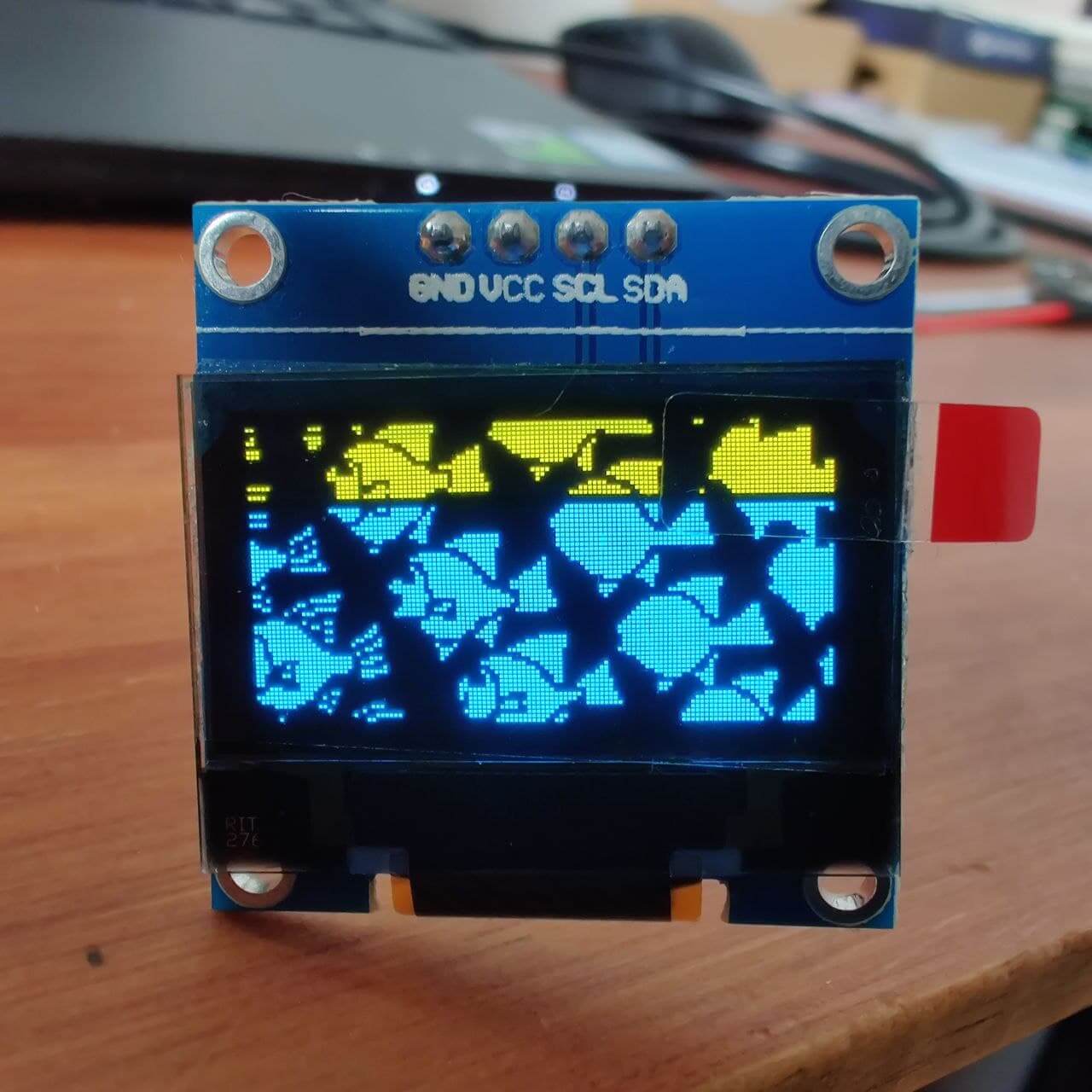
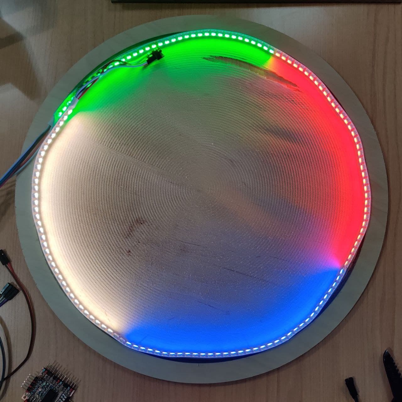
Testing how power affects the color in the pixels.
- First image: brightness 20%. With external power
- Second image: brightness 20%. Without external power
- Third image: brightness 80%. With external power
- Fourth image: brightness 80%. Without external power
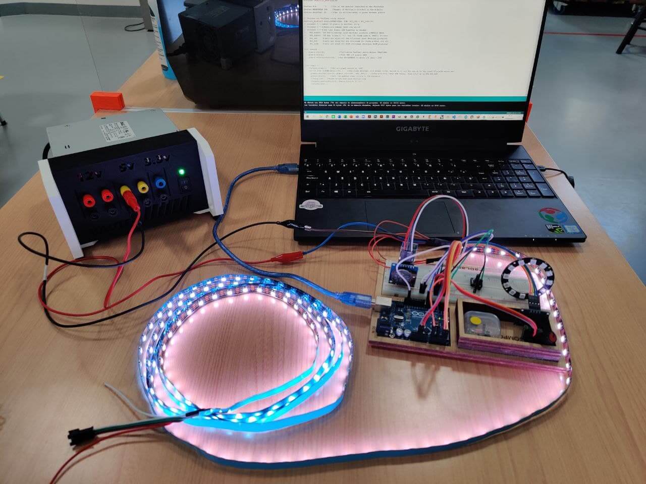
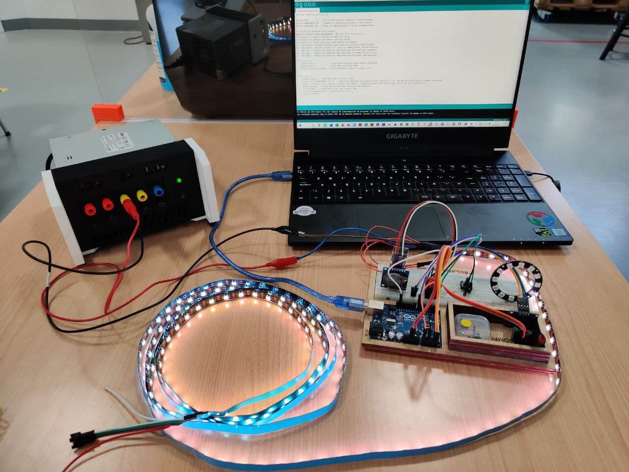
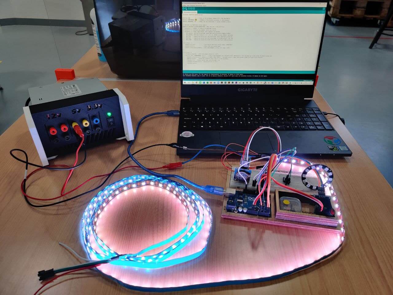
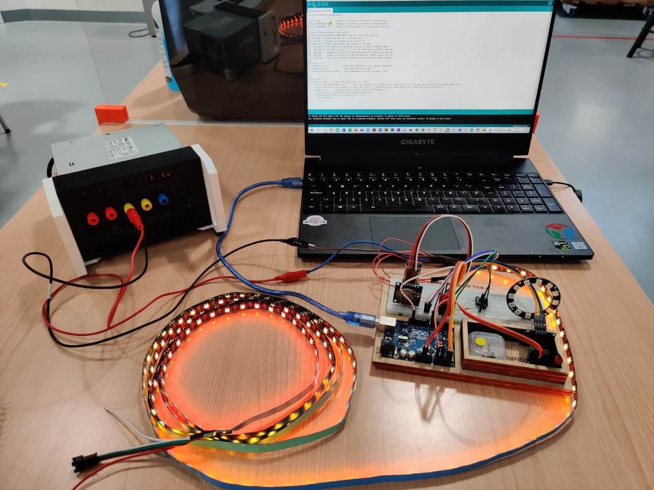
Power draw is going to be an issue. I’ve calculated that a 5V 10A power source is needed.
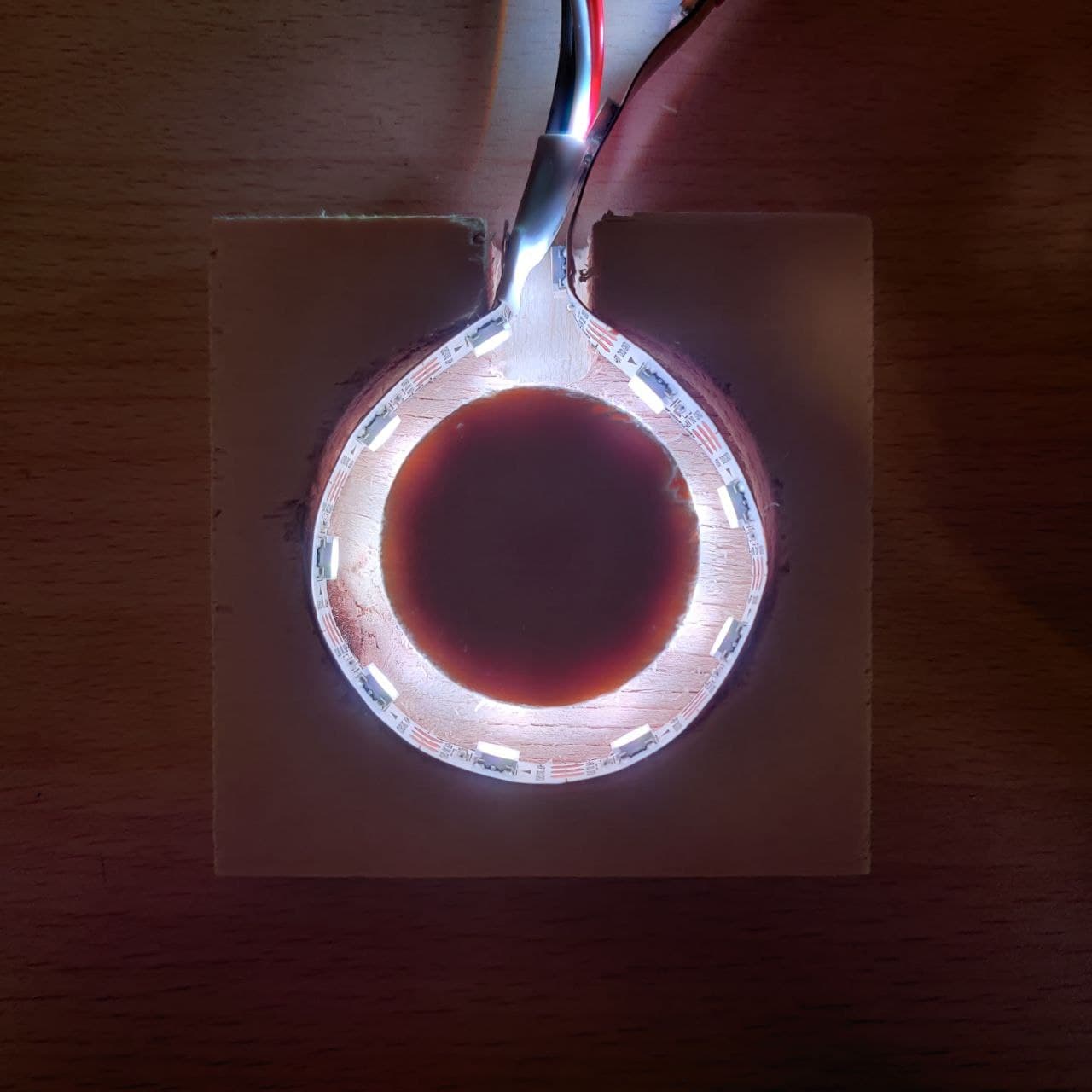
Testing transparency. Wood looks ok but the pixels are too visible. I want a more dense led strip.
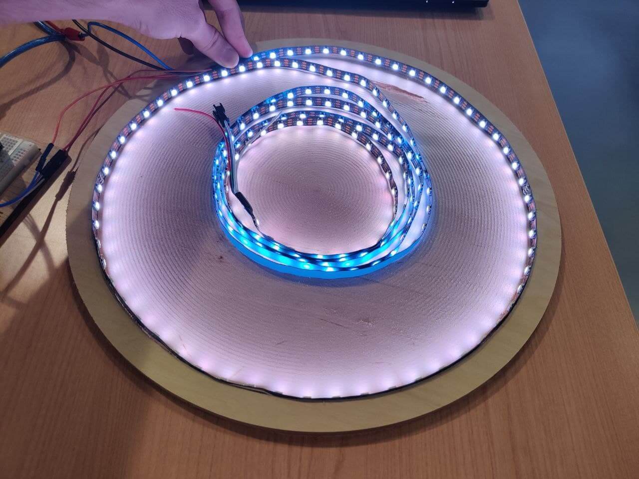
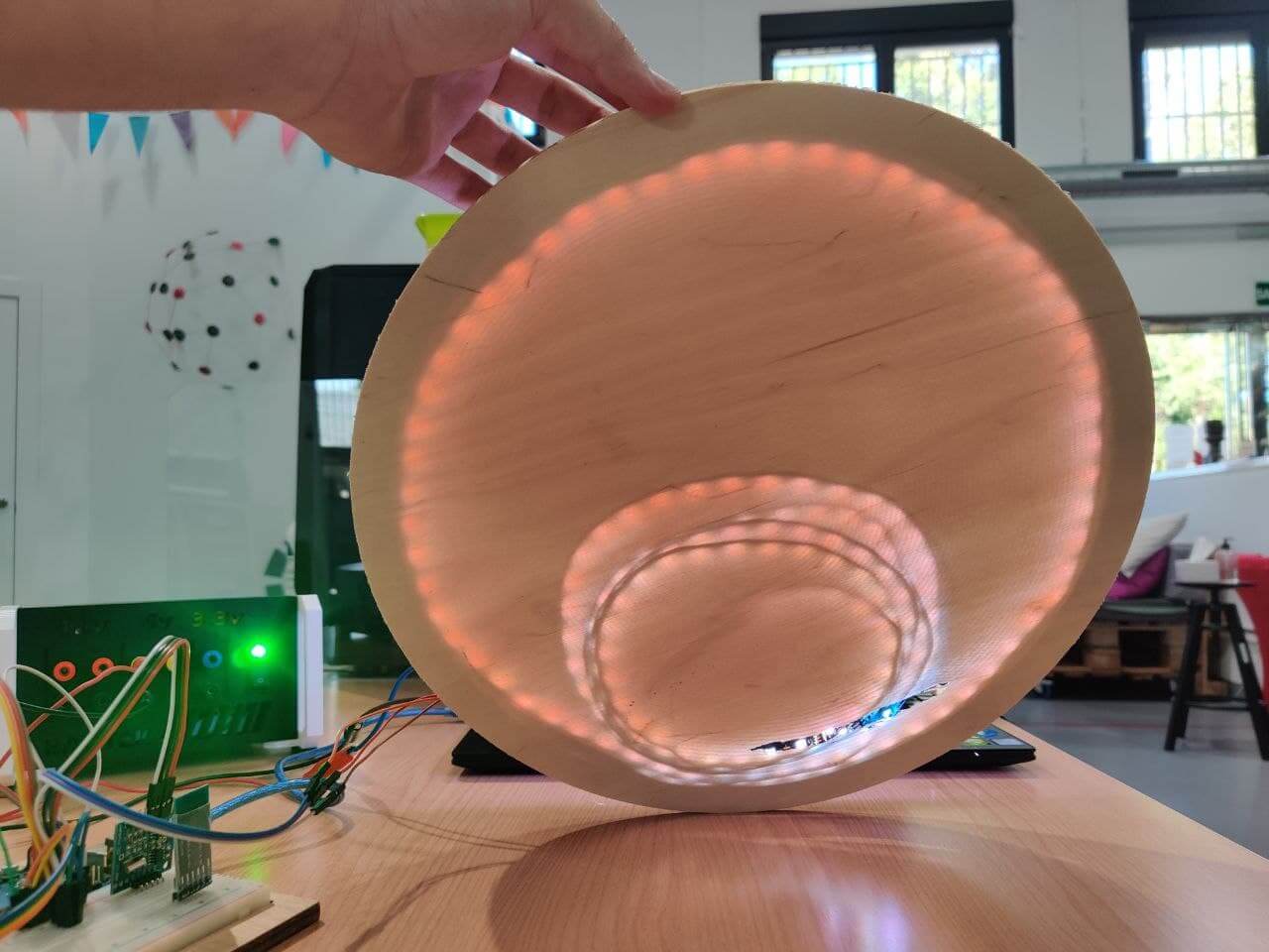
Using the final 1 meter sk6812 neopixel strip with 144 leds/m.
Potentiometer⚓︎
const int analogPin = 4;
int value;      //variable que almacena la lectura analógica raw
int position;   //posicion del potenciometro en tanto por ciento

void setup() {
  Serial.begin(9600);
}

void loop() {
   value = analogRead(analogPin);           //realizar la lectura analógica raw
   //(leyendo [int VALUE] del potenciometro por serial, obtenemos que X es el min y Y el max: map(value, X, Y, 0, 100))
   position = map(value, 0, 1024, 0, 100);  //convertir a porcentaje

   Serial.print("VALOR RAW:");
   Serial.println(value);
   Serial.print("PORCENTAJE MAP:");
   Serial.println(position);
   delay(500);
}
Fabrication⚓︎
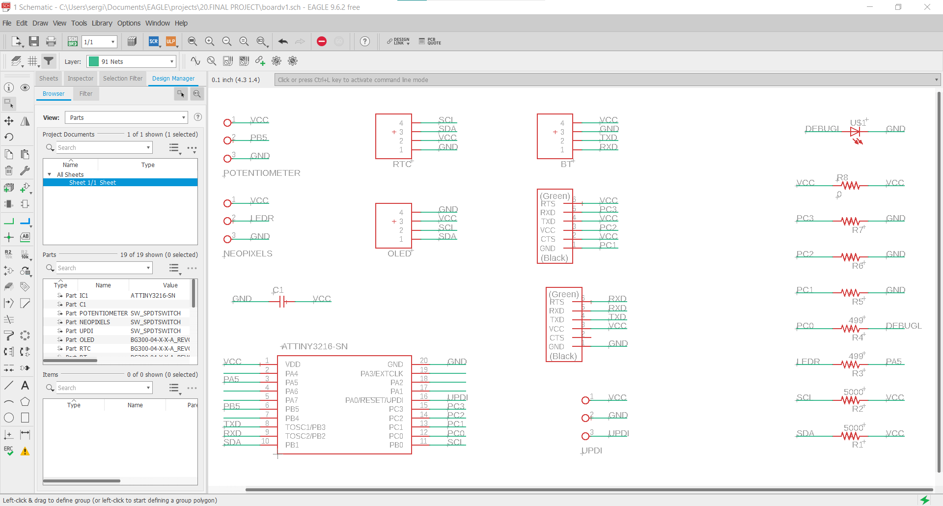
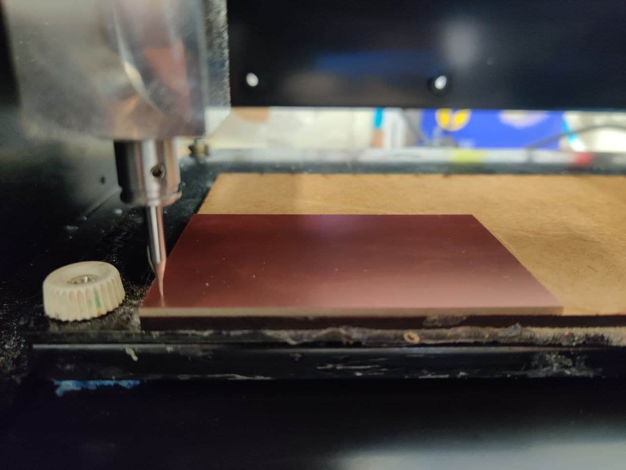
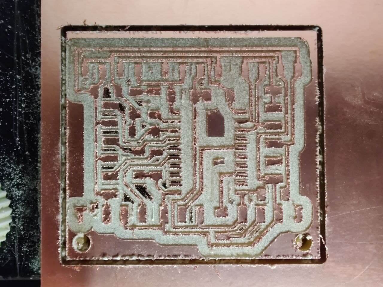
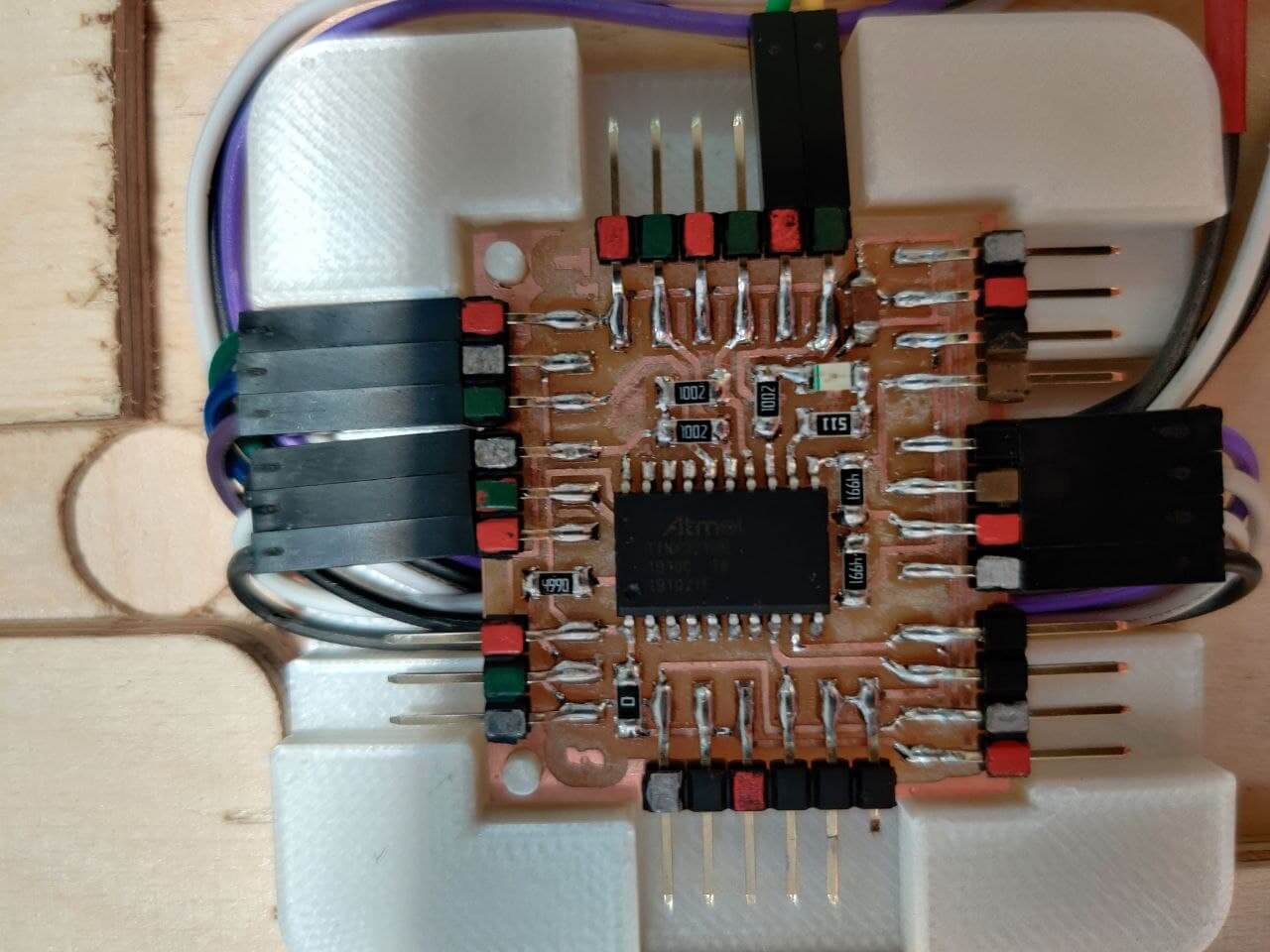
Board⚓︎
Design
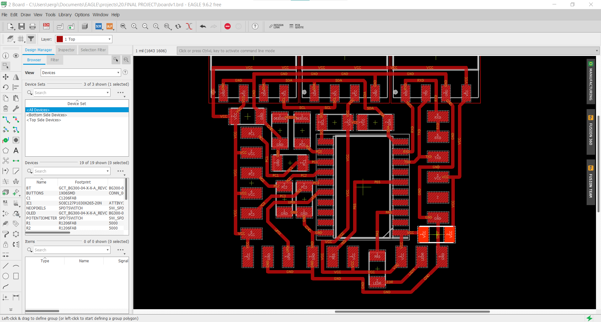
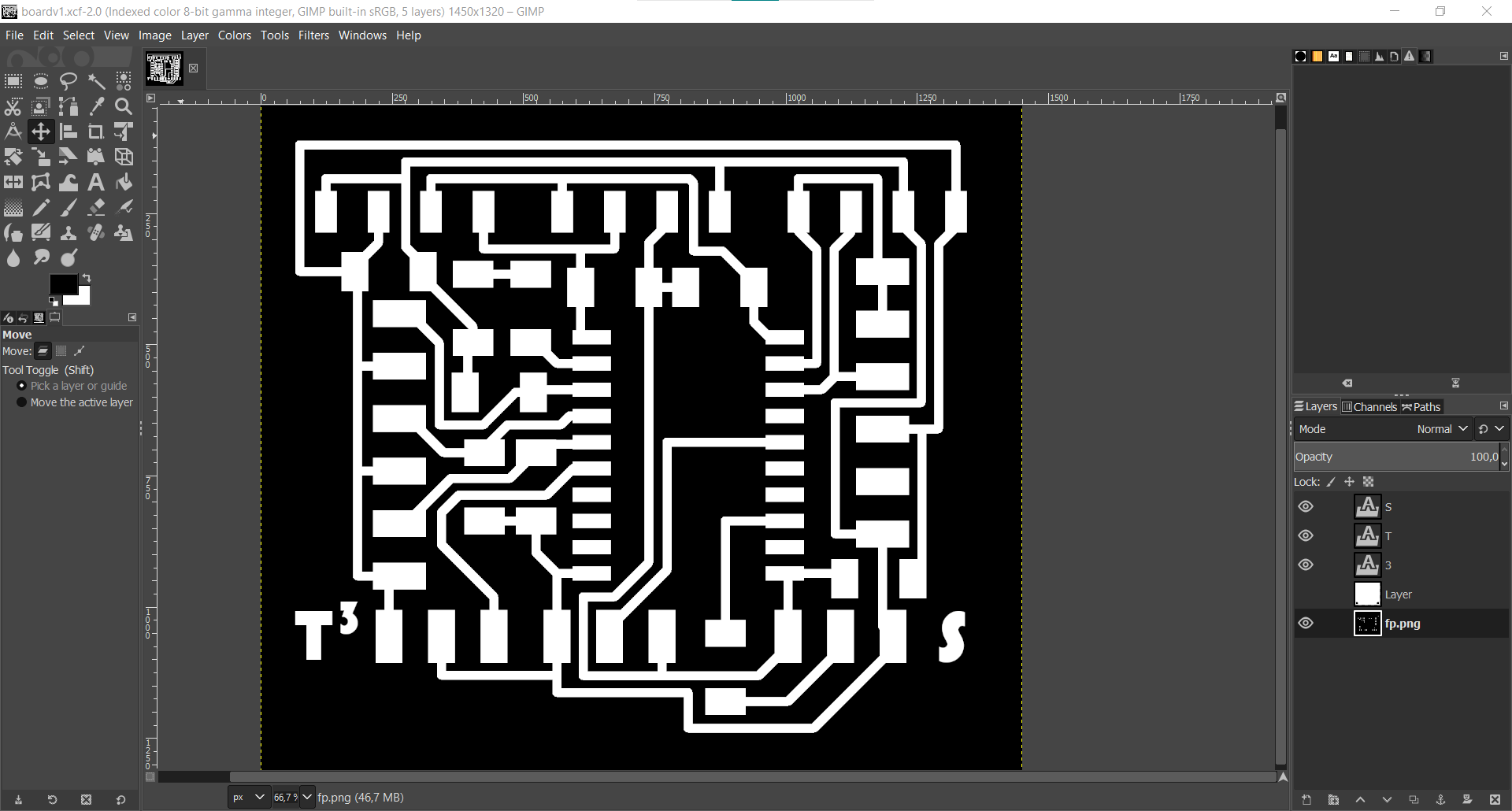
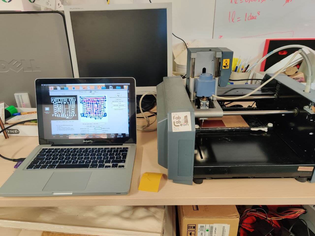
Fabrication

Frame⚓︎
Design and preparation of the files with Aspire for milling
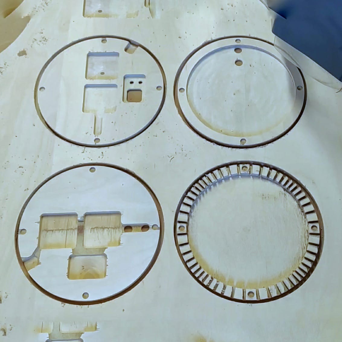
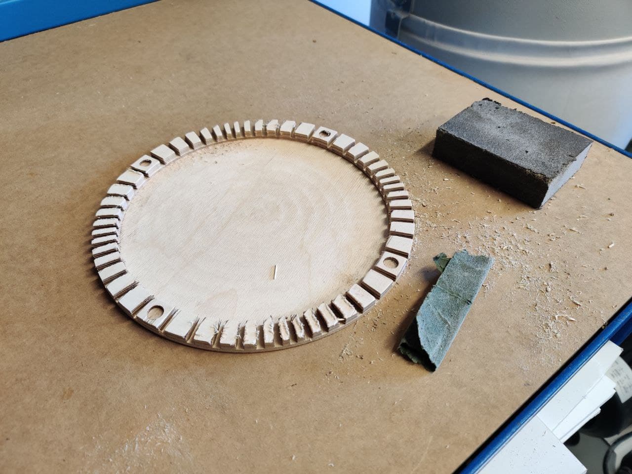
Milling the frame out of 4 layers of 9mm birch plywood

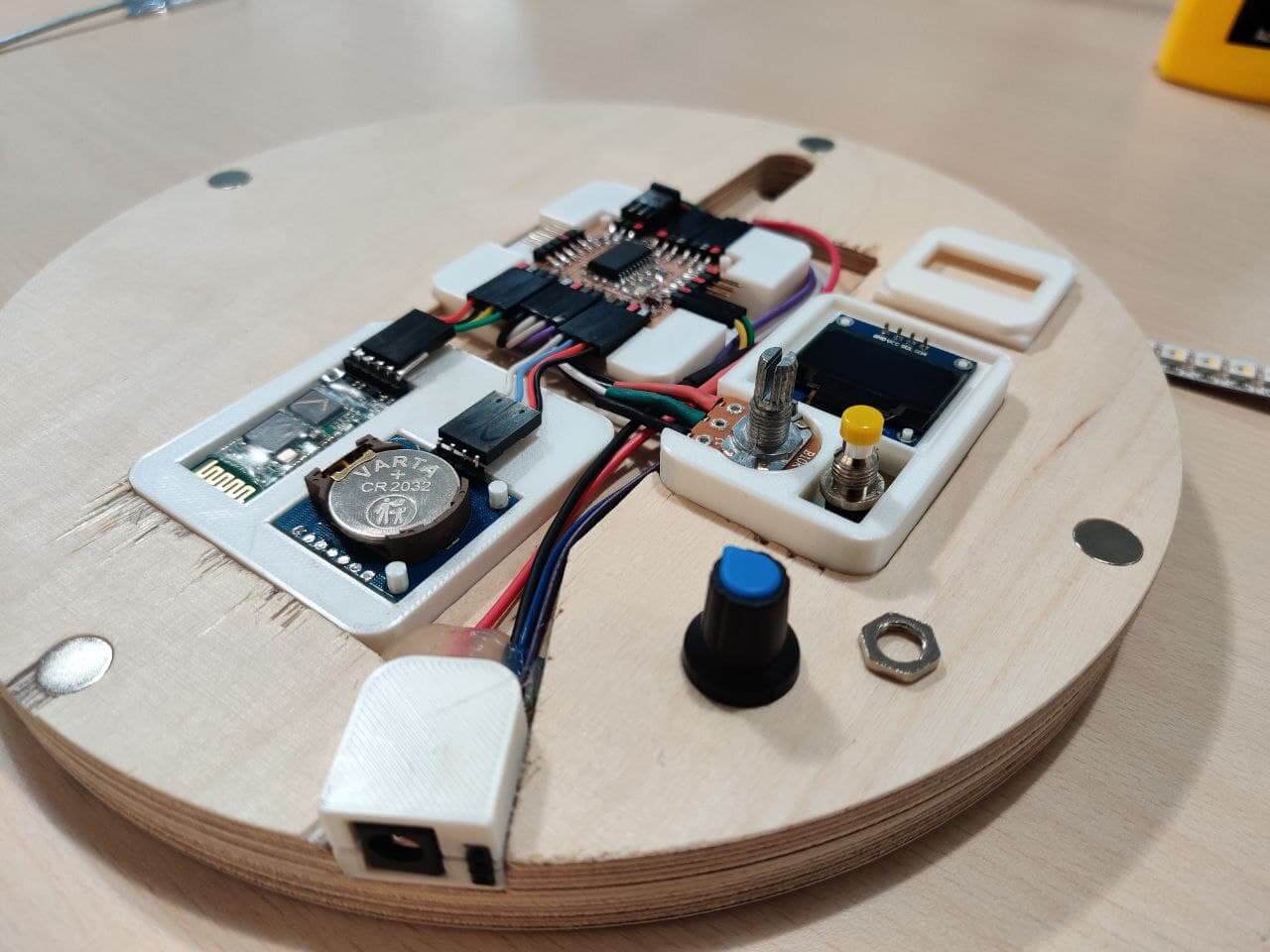
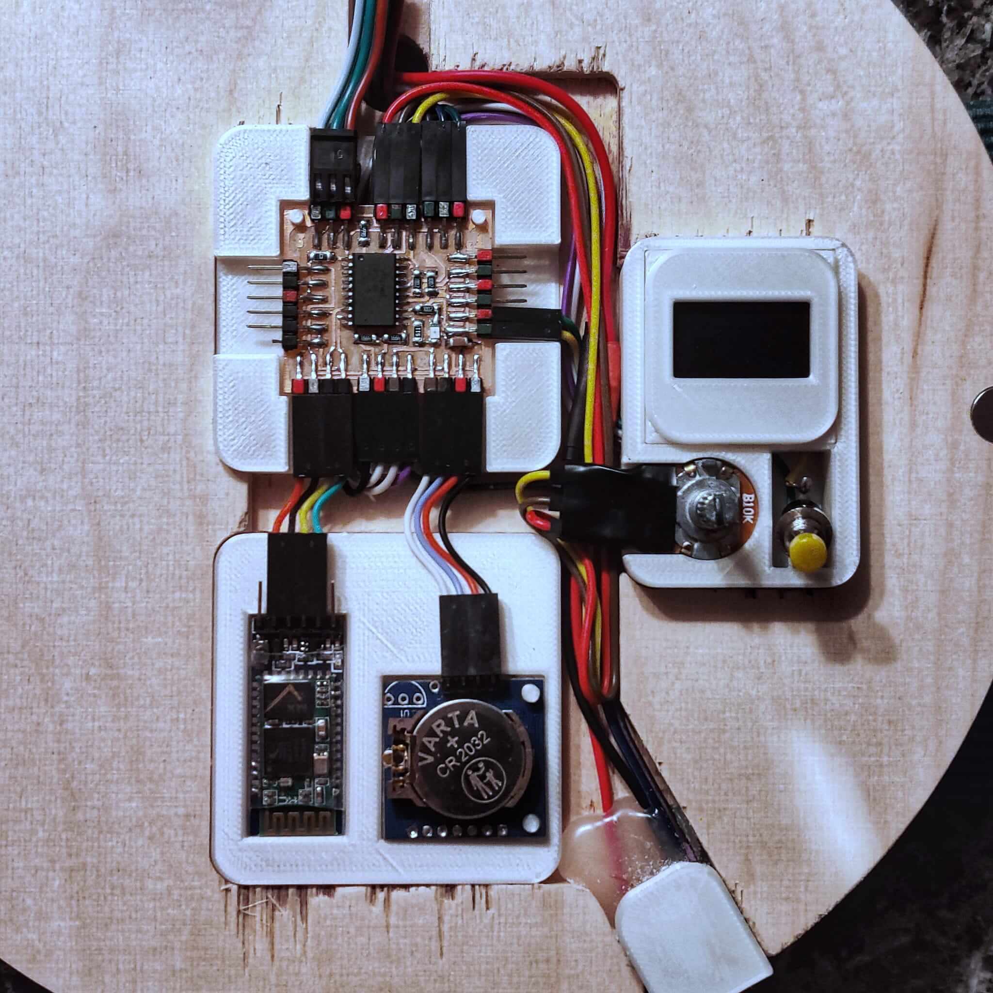
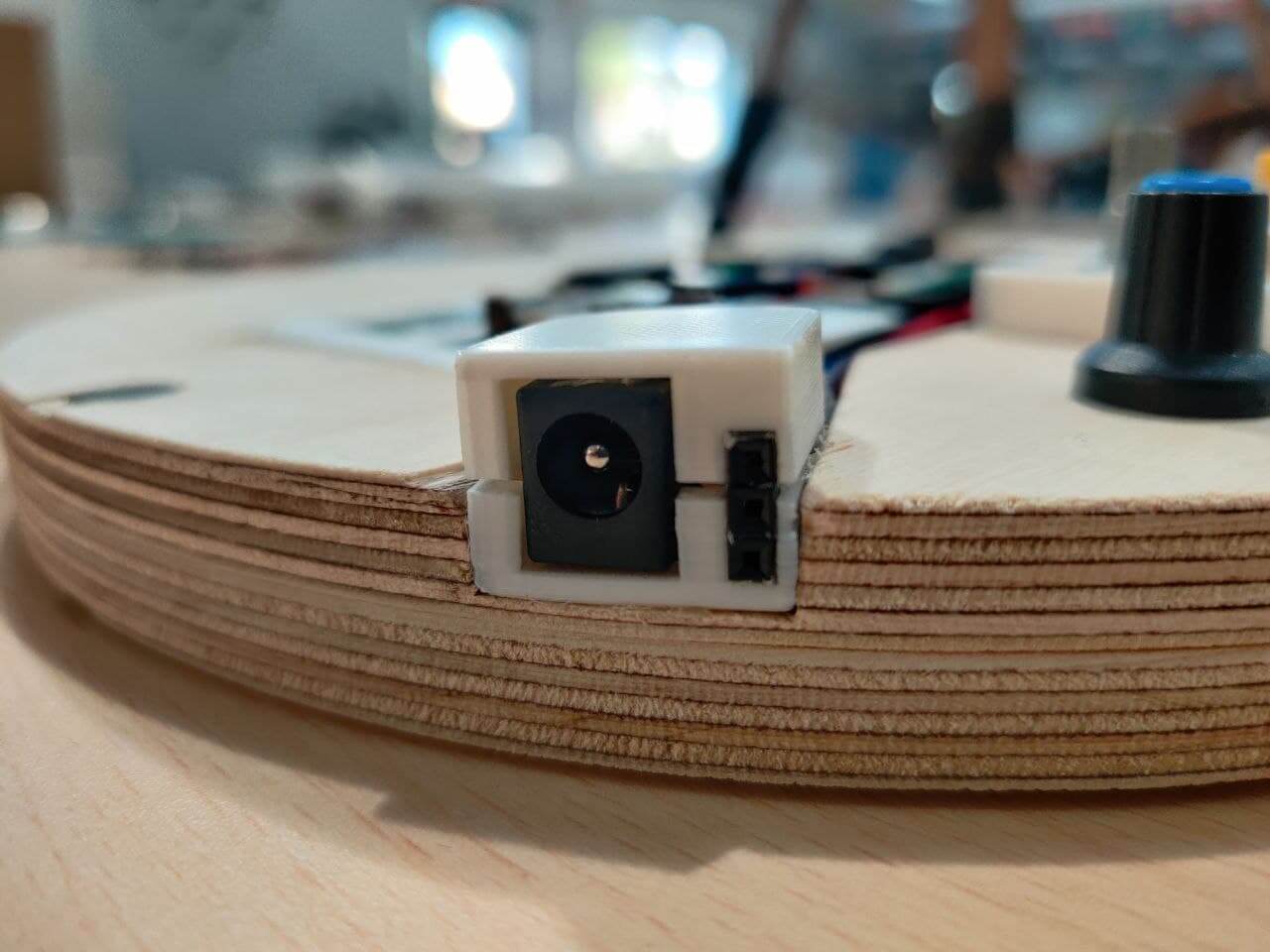
System integration⚓︎
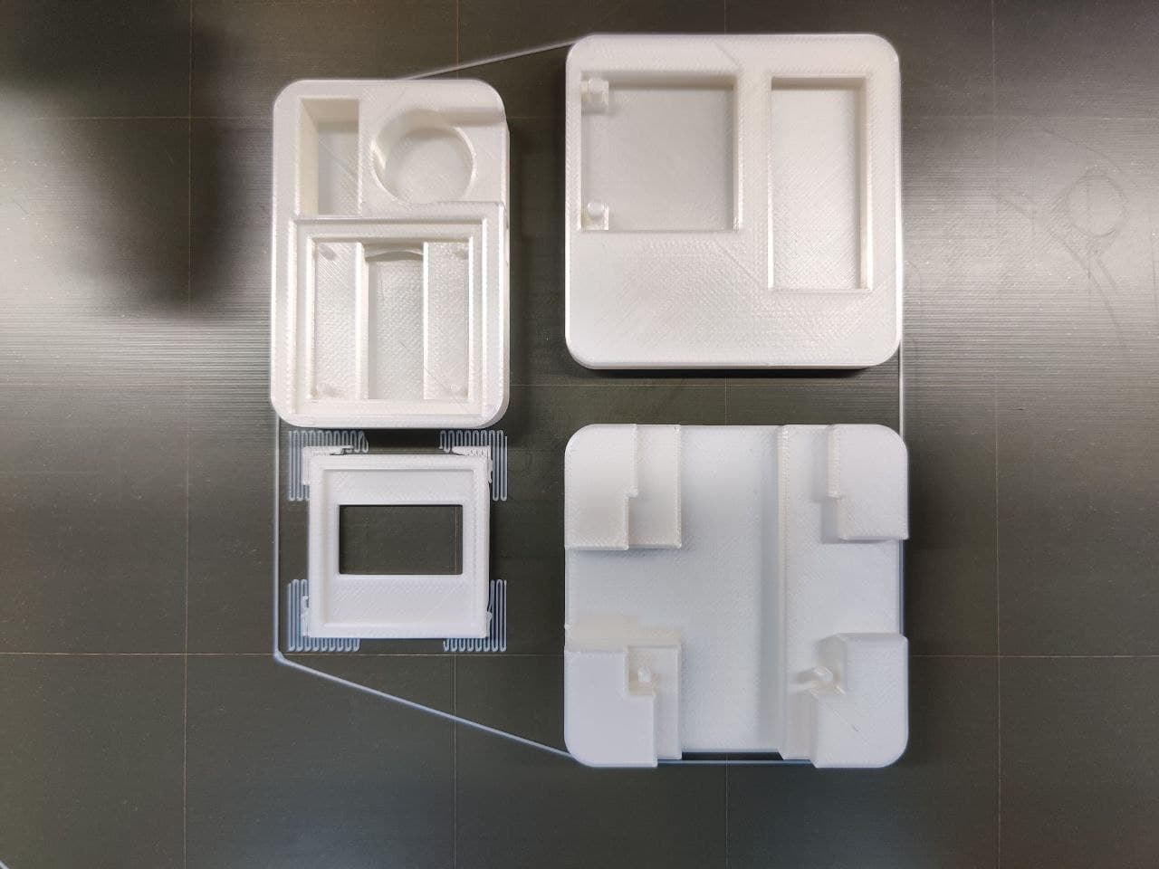
3D printing the casing for each component to fit on the wood frame

Assembly of all the parts
Iterations⚓︎
First⚓︎
With Arduino UNO, 12 led Neopixel ring, code v1 and without casing.
Second⚓︎
With ATtiny3216 board, ws2812b led strip, code v2 and protocase.
Third⚓︎

Finished⚓︎
BOM⚓︎
Materials⚓︎
- Materials:
- Birch plywood for the casing.
- FR1 copper plates for the board.
- PLA for the system integration parts.
- Magnets, wires and connectors
- Methacrylate for the watch face
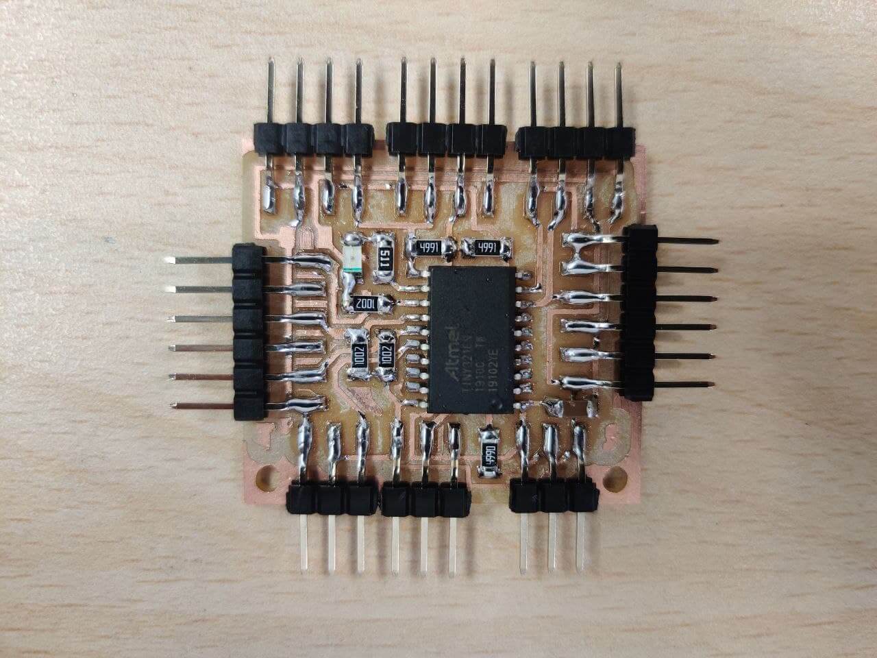
- Electronics:
- AtTiny 3216
- Led SMD
- Capacitor 1 uF
- Resistance: 0(x1), 0.5K(x2), 5K(x2), 10K(x3)
- 6 pin male connector (x2)
- 4 pin male connector (x3)
- 3 pin male connector (x3)
- Inputs: RTC, Potentiometer, Buttons.
- Outputs: OLED display, Neopixels, Bluetooth module.
- Power Supply: PC modified one for testing, Power brick for final product
Price⚓︎
- 20€: Birch plywood
- 10€: Methacrylate
- 35€: Neopixels
- 25€: Power brick
- 2€: Inputs (RTC, Potentiometer)
- 10€: Outputs (OLED, BT module)
- 5€: Board and electronic components (FR1 board, ATTiny3216, resistances, capacitor)
- 10€: Other consumables (cables, connetors, magnets)
Total cost: 117€ approximately
Costs can be reduced a lot without compromising functionality. If we choose a normal W2812b neopixel strip whitout specific white channel and less leds/m, cheaper wood and our PSU instead of the custom 5V 12A power brick, I think we can cut the cost in half.
Questions⚓︎
-
What tasks have been completed, and what tasks remain?
In general all aspects of the project are covered. From the software to the design, electronics or system , all have an acceptable development. Even so, the project has a lot of room for development. The main pending objectives would be linked to the software. Getting the clock to show the time as the basic mode of operation, and the development of the app to communicate with the project through the bluetooth module, and use the device as an interface.
-
What has worked? What hasn’t?
This question is closely related to the above. The main problem and future development point is the software. The last codes that I have uploaded to the project make it have a herratic behavior, so it should be improved. In terms of a more general aspect, the main problem in development has been planning and time management. Perhaps with a more concrete plan the result would have been better. On the other hand, highlighting how trying to develop all the parts as a whole has given a very positive end result, as a final product.
-
What questions need to be resolved?
The main questions to answer is if it works, how well it’s made, and if it fulfills its function. If the user can interact with the interface, start a timer and the leds turn on correctly it should be a successful project! As a second requirement would be a nice integration of it’s parts and in consequence a beautiful project!
-
What will happen when?
The final presentation is on June 11th. At that time Neil will evaluate the project. Also I have seen that Prusa has a contest for time management objects that include 3D printing so I will submit mine to see if I can win. Finally I want to keep developing these not working functions that will improve the functionality of the project.
-
What have you learned?
The correct question should be, what have you not learned? The project has been for me the final adventure of the course, where I have combined all the techniques learned during the course, as I emphasize at the beginning of the project development, with each learned technique that was going to be used in the process. Regarding the process of the project, I have learned the use of new components, such as the neopixels, the potentiometer or the Arduino UNO board. Also some new CNC milling techniques such as recessing or translucent wood.
License⚓︎
Time The Time © 2021 by Sergio Herranz is licensed under Attribution-NonCommercial-ShareAlike 4.0 International. To view a copy of this license, visit cc.org/licenses/by-nc-sa/4.0/
Time The Time by Sergio Herranz is licensed under CC BY-NC-SA 4.0![]()
![]()
![]()
![]()
Files⚓︎
- Clear wood test(
.3dm): file - Clear wood test(
.dxf): file - Schematic (
.sch): file - Board (
.brd): file - Traces (
.png): file - Exterior (
.png): file - Main code (
.ino): file - 3D printed component fittings (
.stl): file - Main design file (
.3dm): file