4. Computer controlled cutting
This week I worked on lerning how to use the vinyl and laser cutters.
This also meant that I had to further explore design processes aimed at production on Fusion360, Rhino, Illustrator and Inkscape.
Vinyl Cutter
Since one of the jobs I had was in a print shop I had previous experiences with the vinyl cutter machine. Nevertheless it was nice to go back to this machine and learn the software and process of a different model from the one I used to operate.
Characterization
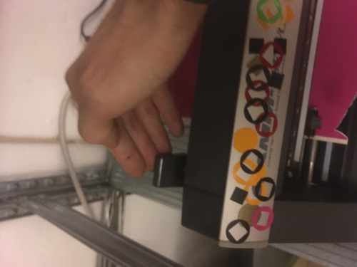
The machine we have at Opendot is a Roland GX-24.
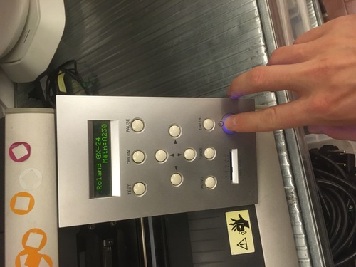
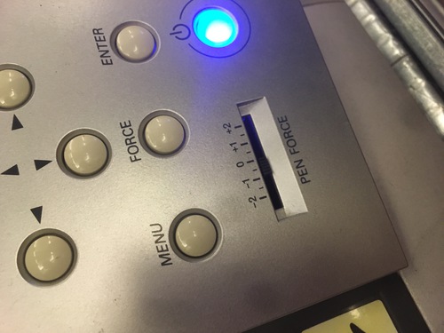
To operate this machine you have to follow a series of steps on the machine itself:
- Load the roll
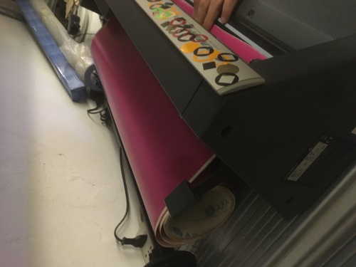
- Align the roll with guides
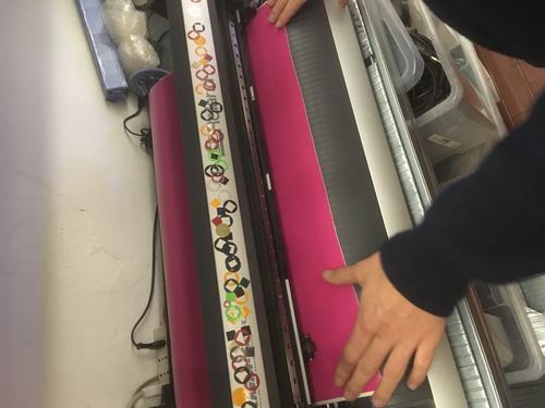
- Align jockey wheels with guides
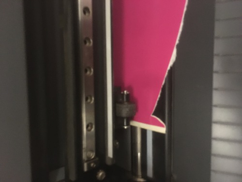
- Close the clutch mechanism that holds the roll in place
- Select whether you loaded a roll, a piece or a sheet of vinyl
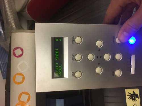
- Set the origin
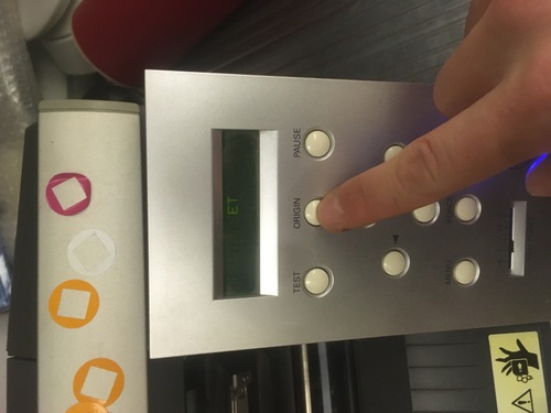
- Test the blade
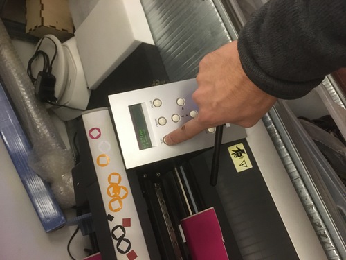
- Adjust force for cut optimization
I did not adjusted the cutting speed that was set at 500 mm\s. In regard of the cutting force, the Roland ranges between 30 and 350 gf. The normal cutting force is about 160 gf, I adjusted for it to be a little less than this in order to reduce setress in the sharpest corners of the design.
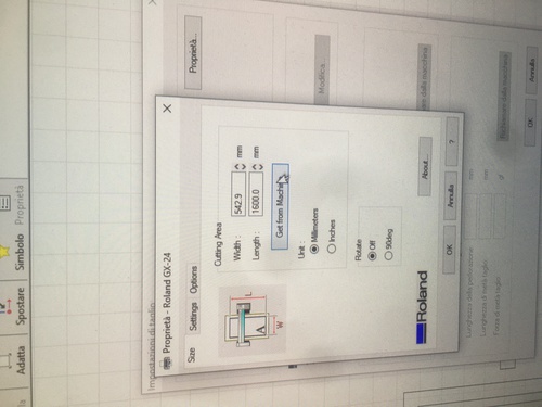
There are also a series of steps to be taken on the computer:
- Save the file as .svg.dxf
- Open the file on Inkscape
- Open the Roland Cut Studio extension
- Select cut options and printer proprieties
- ‘Get from Machine’ to inspect correct width of the vinyl roll
One Colour Sticker
The first sticker I did was a single colour sticker of the logo of one of my side project: Telebomba
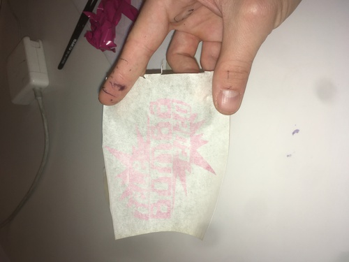
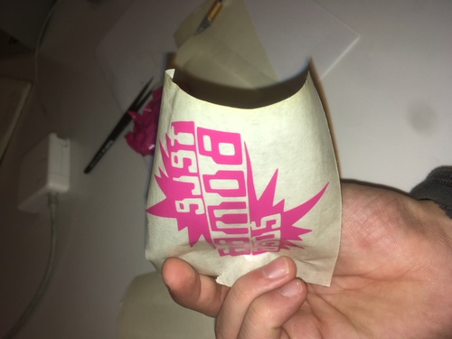
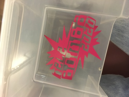
Due to it’s small size, and the sharpness of some of the angles, it wasn’t the easiest sticker to peel, it came out nicely nonetheless.
Two Colour Sticker
In order to further explore this machine I decided to try a double layer sticker.
I quickly designed a logotype of my name that was divided in half playing with negative space. I separated the two layers and added a square shape on each side so that to have a visual guide for aligning the two layers on the sticky tape.
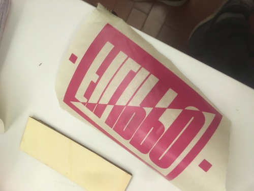
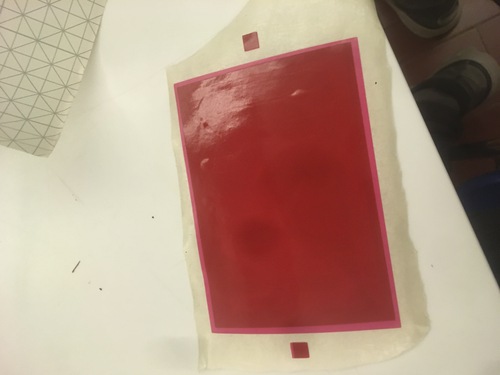
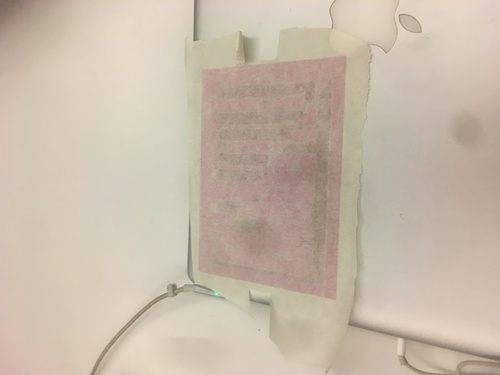
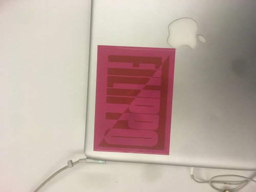
I quite like the result as the straight lines, double outlines and gentle angles allowed for a precise weeding process. I also find the low contrast between red and pink quite pleasing.
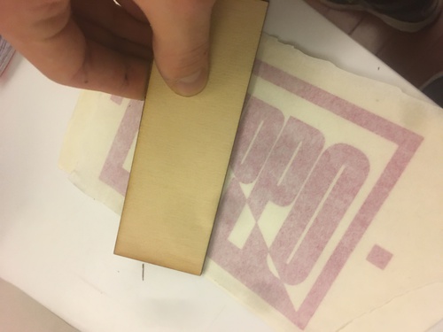
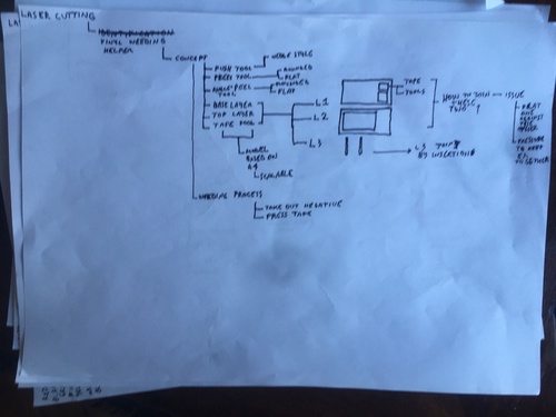
Weeding Tools
In order to facilitate my weeding process I laser cut 3 tools.
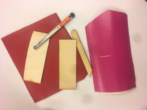
- An elongated “push tool”, with and narrowe side and a round side that I use in order to keep the smaller pieces of vinyl in place and to keep the vinyl stuck to it’s base surface when I pick vinyl in precise\small parts of my design
- A rounded edge tool I use to facilitate peeling of bigger areas
- A square edged squidgy tool i use to make the layers of vinyl, the sticky tape and the final surface stick properly, I also use it to eliminate air bubbles if I wasn’t careful enough when laying down the sticker
I use these together with a small cutter (or a pick), sometimes small tweezers and a piece of masking tape where I stick the excess vinyl in order to reduce mess and confusion while weeding.
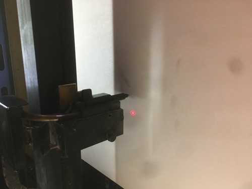
Laser Cutter
It was my first experience laser cutting. Although my first impression suggested me that the process was somehow straight forwards, I soon find out that there’s a lot to take in consideration when utilising such machine, especially a lot to take in consideration when designing the files.
Characterization
Machine: GCC SpiritGLS.
It is a powerful machine that cuts wood and polymers. It’s resolution goes up to 1500 dpi, features a laser powerful up to 100W, auto-focusing system, table size is 860 x 610 mm.
To operate this machine you have to follow a series of steps on the machine itself:
- Place the material onto the cutting bed
- Put weights onto the material to reduce warping
- Set\focus the Z axis
- Turn the aspiration vent on
- Position the laser head where you want the cut to start (in case you use the ‘relative’ setting when deciding the origin)
There are also a series of steps to be taken on the computer:
- Save the file as a .dxf
- Open the file on Rhino
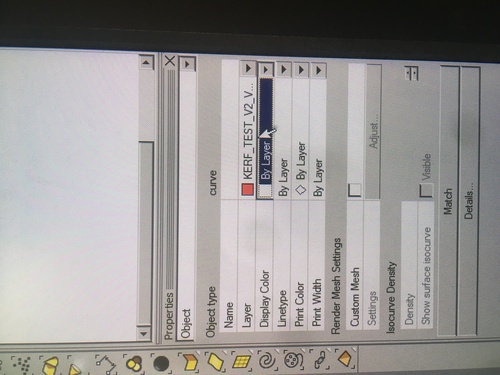
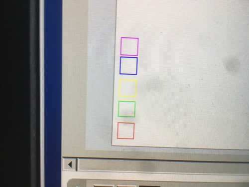
- Assign each shape to the correct layer (each layer can be a separate operation with different speed\power settings)
- Select layer colour and display shape coulours by layer
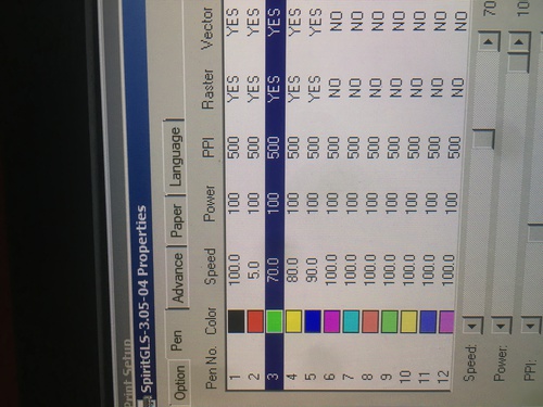
- Go into the print proprieties
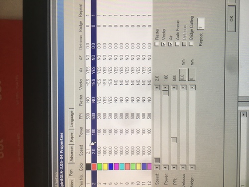
- Set pens proprieties (speed\power, vector\raster)
- Set origin mode (home\relative)
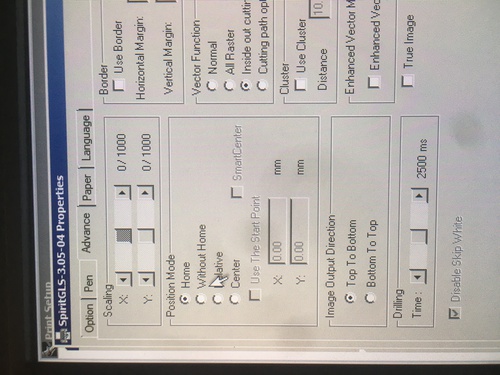
- Position the elements to by cut into the area where we want them to be cut
Tests
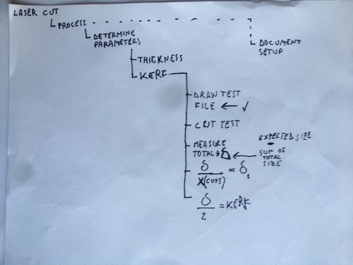
I operated a series of tests in order to determine the kerf, different engraving and cut speeds or even simply to get comfortable with the machine.
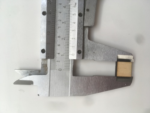
Kerf Test
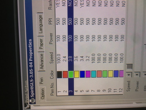
Once I figured out a very low speed that would cut through my material, I decided to increase step by step such speed to achieve a reduced kerf, a higher precision and a less burnt piece of wood.
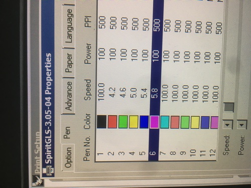
I worked with lines of 5 blocks, with an increment\decrease of 0.2 (sometimes higher) in between each of of them, I worked in cross both starting with my minimum speed of 2.1 (that would give me an highly burnt piece of wood) and from a maximum of 6.4 (which wouldn’t full cut my wood).
These were the results.
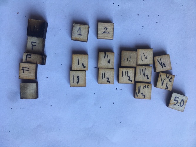
So I measured my blocks. At 2.1 speed I had a total side lenght of 9.54mm, that would give me a delta of 0.46 mm, so an offset on my CAD file of 0.23. I found my ideal\most precise cut at 5.0 speed, which would cut a block measuring 9.78 mm, which would account for a kerf of 0.22 mm (offset 0.11 mm). Within a few minutes it was possible to reduce the kerf in half operating these tests.
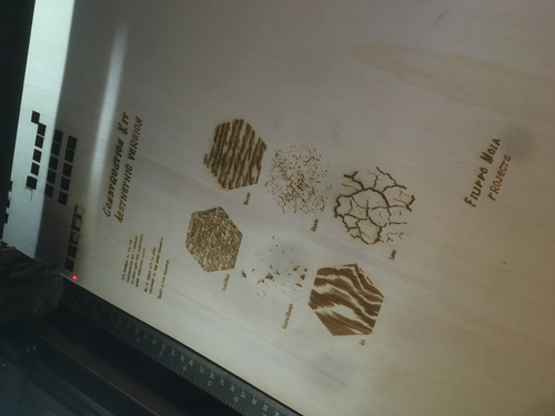
Engraving Test
I proceeded to do similar tests, this time focusing on engraving. I had problems that I yet haven’t solved in importing correctly to Rhino a .dxf designed on Illustrator. This radically made my work harder.
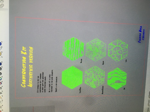
Just as with the cuts, each layer corresponded to a different speed, here ranging in between 100 and 60 with 10% increments.
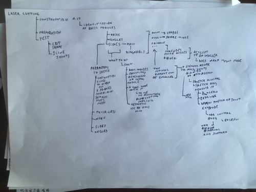
Parametric design
I made some huge design mistakes in the first file I designed. The mistakes lead me to an extremely time consuming process as I firstly designed my shapes segment by segment adding the lenght and angle parameters one by one. My second mistake was that I added kerf to the lenght of the positive cuts and took it out from the subractive cuts.
I later figured out with that, the shape I drew being modular, I could much quicker draw it using circular patterns, it was much quicker to unify my sizes and angles by using the Equal constaint and that the kerf was to be added in one step using Offset.
Adding parameters
In order to add a parametre that will later be used in the design, one has to:
- click modify
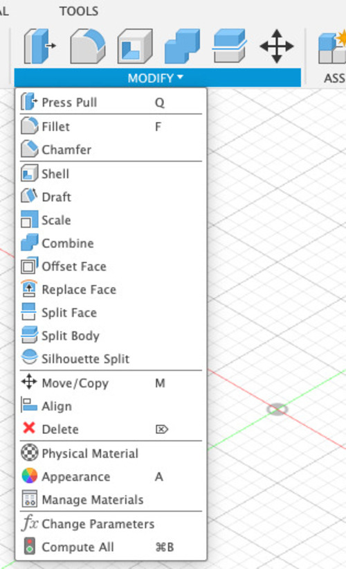
- select change parametre
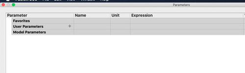
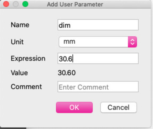
- add User parametre
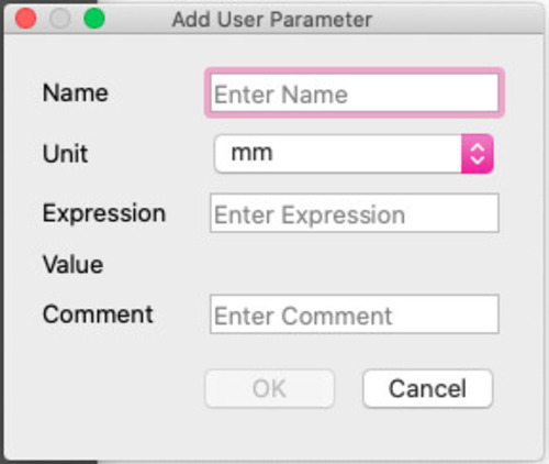
- select the dimension, choose a name and unit
Using parameters
This one is pretty strightforward: once you need to use a specific parametre, just type the name of such parametre in the log box in which is needed.
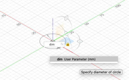
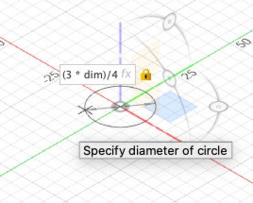
One can also use a parametre inside a function.
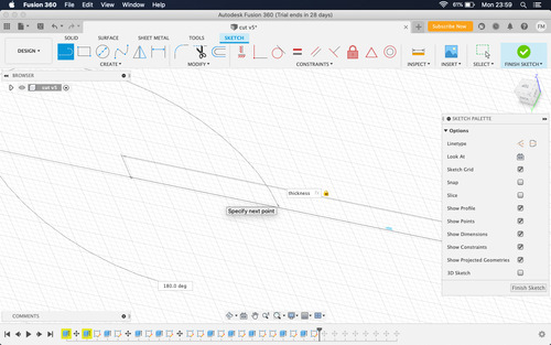
Wrong design
The parameters I set were the thickness of my material (which also stood for the lenght of my segments), the angle for the segment of each side (90°) and the angle in between each side (120°).

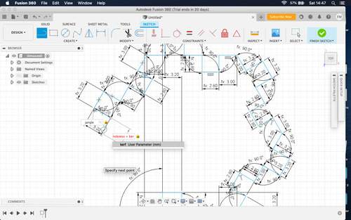
I wrongfully drew each segment one by one.
Same for the holes that i decided to take out in my final design.
An example of my basic shape in the wrong design.
A lot of segments, a lot of wasted time.
Even more segments, even more wasted time.
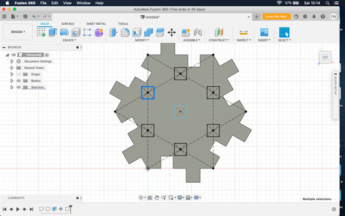
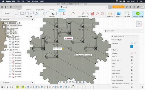
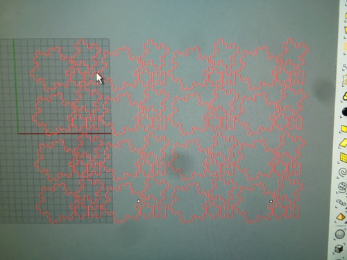
Right Design
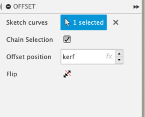
In the correct files I only set 2 parameters: - the thickness of material (which also is the lenght of each segment) - the kerf

I then drew one segment adding the correct parameter and the number of segments for one side at the correct angle.
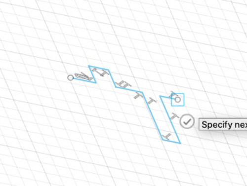
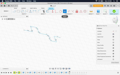
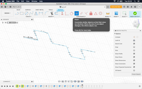
I then used the equal costraint to make them identical.
I drew a edge polygon of 6 sides with construction lines.
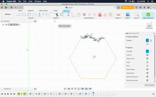
I used a circular pattern to create my basic shape.
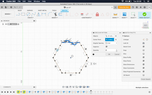
The second shape was done by duplicating one side of my basic shape and repeating the process, basing my circular pattern on a square.
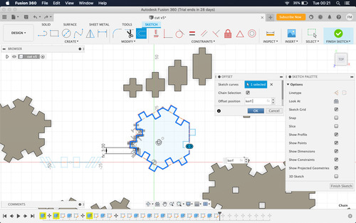
The joints were designed using mirror.
I added the kerf using the offset.
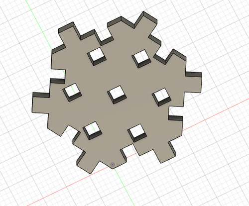
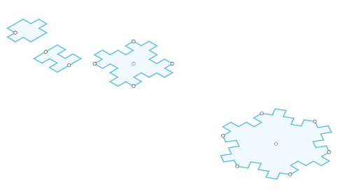
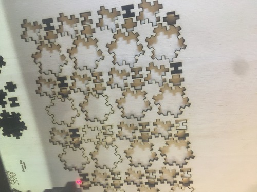
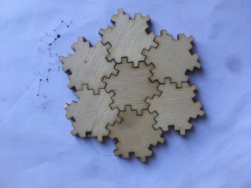
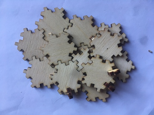
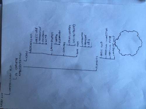
Press-Fit kit
I drew a modular kit that can work to represent isopleths or design miniature based strategic games maps. I can also be used to build structures. Due to the high number of segments and joints, it gives a huge amount of possible combinations.
Additional test
Once I had all my shapes correctly designed I decided to do a new round of tests. I repeated the same cut applying a series of increments in the speed in order to test how the pieces would fit keeping the kerf\offset parameter I discovered for 5.0 speed, but changing the actual cut speed.
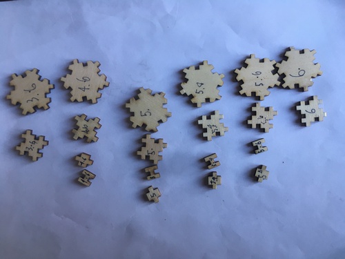
At 4.6, 5.6 and 5.4 the difference was not too noticeable, but I would get an higher number of imprecises segments.
At 3.6 the fit was far too snug on perpendicular joints and far too baggy for parallel joints.
At 6 the fit was far too tight on parallel joints and far too baggy on perpendicular joints.
I so decided to stick with the 5.0 speed I had already found.
I therefore sent my file to production.
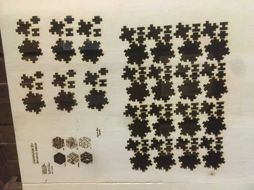
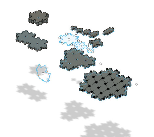
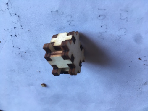
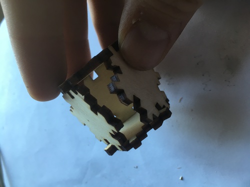
Kit pictures
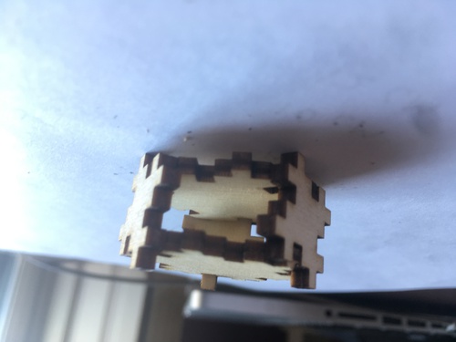
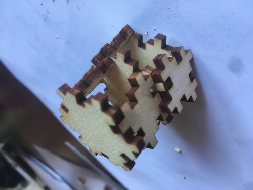
Here’s a series of pictures of structures done with my kit.
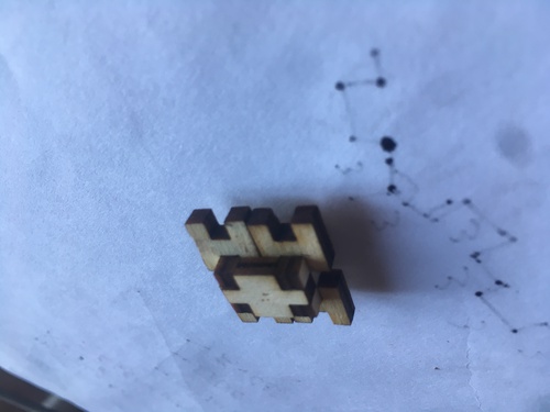
A very solid joint made of multiple joints.
Basic isopleth structure.
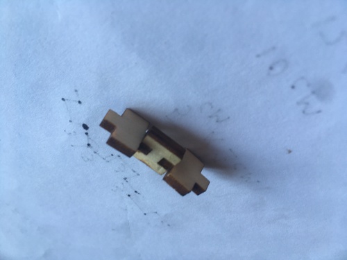
A flimsy sting of joints.
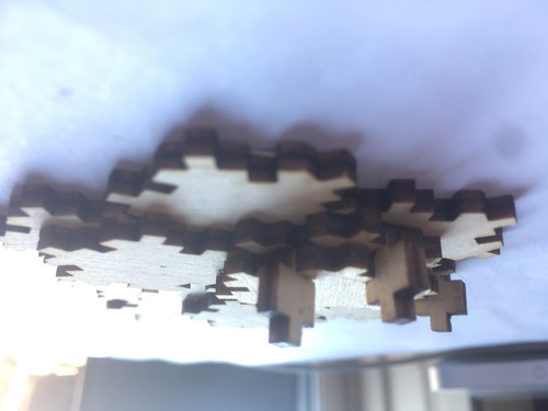
A 3 layer isopleth.
Minimal vertical structure.
To the sky!
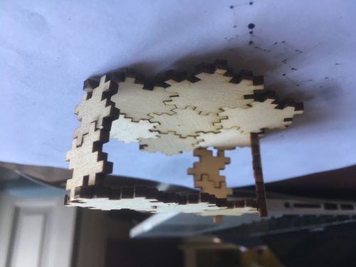
Bridge structure.
A minimal structure of sides and joints.
Minimal structure of basic units.
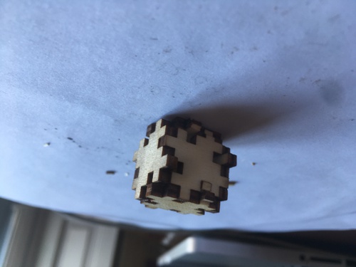
Minimal structure of sides.
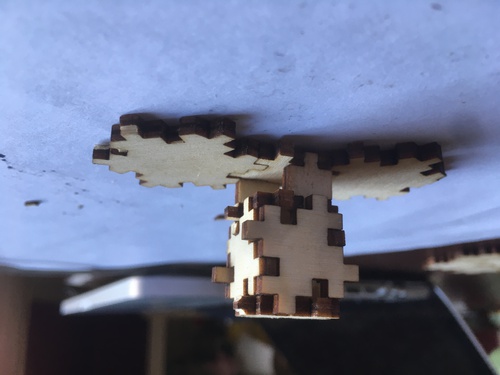
The amount of segments allows for a high variety of combinations.
Confront
My collegues Raji and Luisa also used such machines their work can be seen at these links:
Research, Notes
Files
Task List
- [x] Explanation of parametric file
- [x] Press-fit kit
- [x] Vinyl sticker
- [x] Files