14. Networking and communications
This week I worked on networking and communication between two PCBs.
I used the I2C protocol.
Boards
The two boards I used were two versions of the same system. In the previous weeks I developed a mega328 based PCB, with open pins for all inputs and outputs. This made it very easy to connect the two, and the presence on both of inputs (buttons, potentiometer) and outputs (LEDs) allowed me to work on sketches that didn’t need extra peripherals.
You can find these boards at this link and this other one.
The sole difference between the two boards is that one presents a ground plane and the other doesn’t, the other difference is that one features a 20Mhz quartz and the other a 16Mhz external clock.
Connector
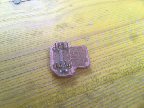
In order to have a more tidy setup, and not mess around with a breadboard, I designed a produced a small connector.
This connector features SDA\SCL, with their relative resistors, and GND\VCC so that the teacher board could power the student board.
I also made a second connector later on to be able to expand my i2c bus to two more boards.
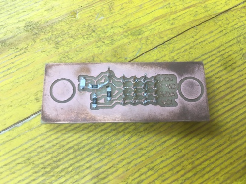
All these connectors feature GND and VCC pins for alimentation, SDA and SCL pins for communications, and the necessary resistors, with a control LED to check power supply as well.
Wired Setup
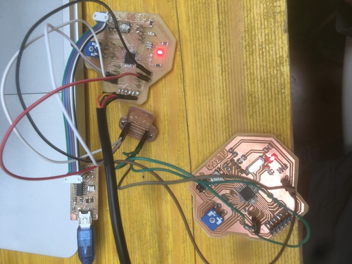
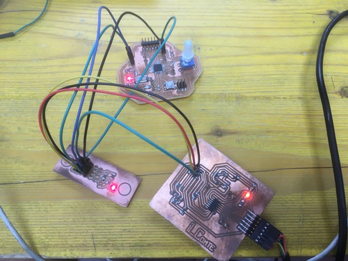
This is how the setup looked once I used jumpers to make the connections.
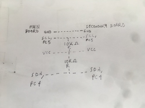
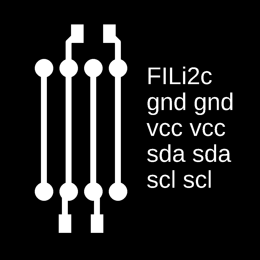
Here is a small diagram of how the two boards are connected, all connection happen through the connector I milled.
GND on first board is connected to GND on second board, VCC on first board is connected to VCC on second board, SDA on first board is connected to SDA on second board, SCL on first board is connected to SCL on second board, 10k ohm pull up resistrs are placed between SCA and VCC and SCL and VCC.
Example
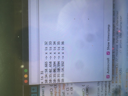
I first tried on of the example codes provided by Arduino in the wire.h library documentation. This sketch would hae one board featuring a button, for each time the button was pressed this board would send a counter information to the main board, that would then communicate that to my laptop via serial communication.
Code and functioning
The first step was to download and install the Wire Arduino library. I then spent some time reading the documentation to better understand the syntax and functions.
I then started to write the code: I decided to iterate on the code I had written for input devices.
In the first iteration I had a button to change states in my board, there were two state each corresponding to a different state in the led (on\off obviously), for each of these state the board would communicate that to monitor via FTDI.
For this iteration, the button, led and states would happen on the main board, which would communicate its states to the secondary board via I2C, then the information was from there sent to monitor via FTDI.
I didn’t encounter much troubles with this code as I have been working with these two boards for a few weeks now. I found out I didn’t need to set a clock divider on both, but solely to the one communicating to the laptop as the clock for the communication between the board is set by the I2C protocol.
The main issue I encountered at first was that the PCB would not send the whole of the characters to monitor, I then changed the position of the line of code and It worked perfectly.
Addressing boards
With my first connector design, I could only bus the two boards, the following design could connect 4 boards.
In both cases the main board does not need an address. The (or any) secondary board is instead to be addressed.
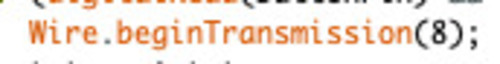
In my code, the secondary board is addressed as 8. The address is a 7 bit address. With 7 bits one can rapresent 128 numbers, which would give 128 different possible addresses, which is the maximum number of boards tha t can be connencted on a i2c bus. 0x00 to 0x08 are reserved. I could have addressed my secondary board or any following board with 7-bit expression of a decimal number such as 0x0c (9) or 0x0d (10) and so forth.
Group Assignment
As group assignment for this week we wrote two new sketches in order to have one of my boards and one of Raji‘s boards to network in i2c.
His board would be the secondary, mine the main one. The secondary board receives values from the main board and communicates them via serial communication to my laptop. The main board would read it’s potentiometre value and send it to the other board.
Files
PNGs