18. Wildcard week
This week I worked on defining expanding the scope of what is doable in a Fab environment. I experimented with four axis small format machining and casting\molding.
Research
My intention was to machine a positive calc for MTB handlebar grips, to later produce a golden standard, to be used to cast grips.
The internal diametre of a grips obviously corresponds to the external diametre of bars. This is luckily one of the few existing bicycle measures’ standards that is shared by all bike components manufacturers: 22.2mm.
In regards of the external diametre I found that most grips manufacturers make the grips’ thickness between 3 to 7mm. I wanted something with a certain level of “squishiness” to dampen vibrations from off road riding, and to add a minimal suspension to a rigid bike.
I asked to some cyclists friends of mine for suggestions on the lenght and design of the grips:
- as much as I thought the opposite, most of them did not want an ergonomic\supportive shape
- they suggested to stick to the standard cylindrical shape
- some wanted longer grips, but for most people a fairly standard 130mm was the most suitable in terms of cockpit organisation
My main ispiration for the design were the classic Oury, to which I added a small flange and knurling all over the model to prevent hands from slipping.
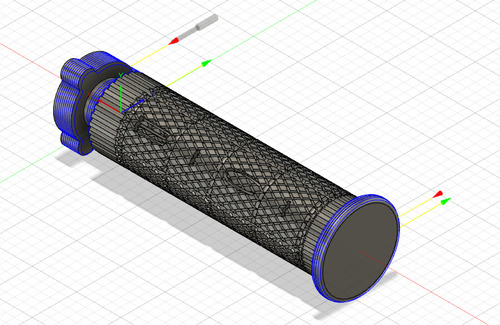
CAD
Tha CAD for both models was made on Fusion 360. It would not only include the grip model (with its features and decorations), but also a part made for the model to fit in a casting jig.
First model CAD
Here’s a short video showing my process.
The hardest part of this process was that I didn’t keep my file tidy: I have an excessive number of sketches and construction planes. On top of that I made the knurling quite early in my design, which made the consequent design steps fairly slow and unresponsive. Another Fusion tool that was hard to utilise was the letter engrave tool.
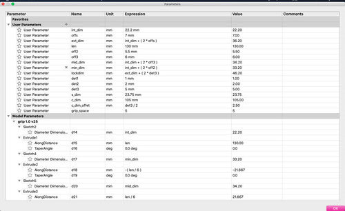
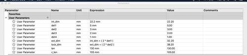
All the design is fully parametric.
Second model CAD
Designing the second model was much quicker and easier, to a certain degree because I knew what I was going to do (reducing the trial-and-error phase), secondly beause I kept my file much tidier.
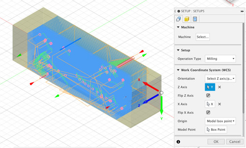
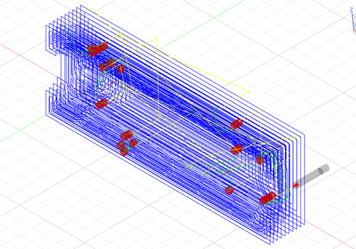
CAM
The CAM for both models was made on Fusion 360. In order to work the best, not only the models bodies were inclueded in the CAM, but also models for the stocks and boundaries.
First model CAM
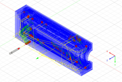
For the first model I did, there were multiple jobs.
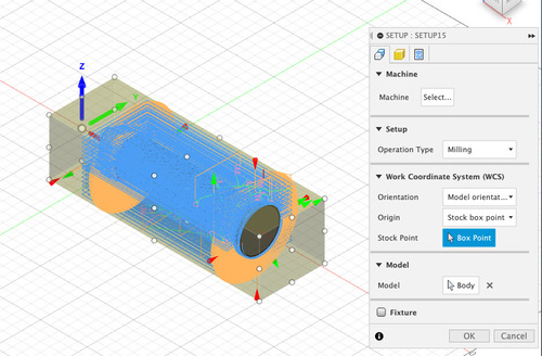
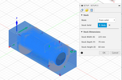
As very first step I created a setup, defining models, stock and job origin.
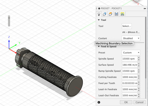
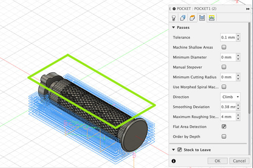
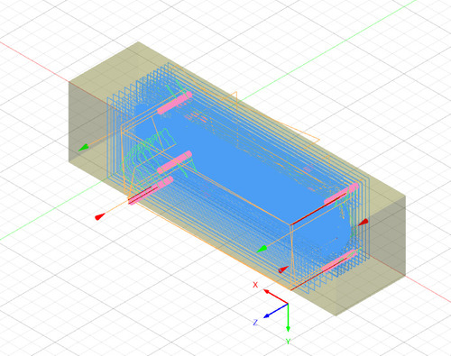
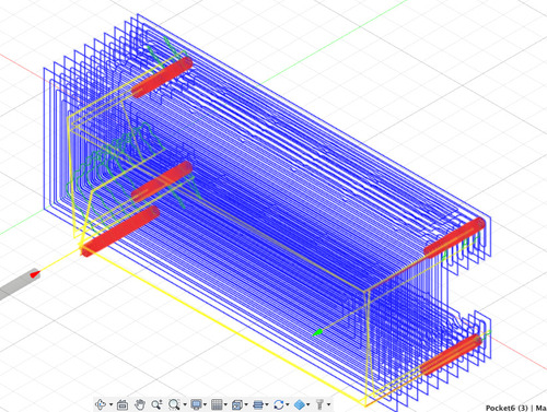
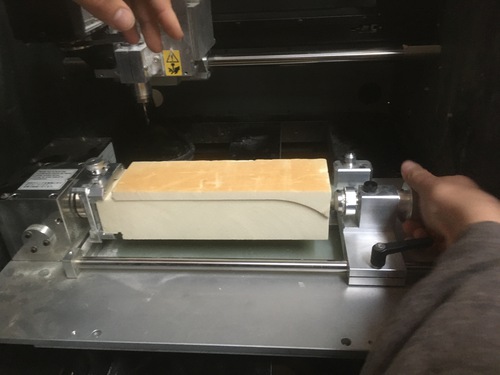
The first job was a pocket clearing, that would clear the top half of the model. It was done with a 4mm flat end mill, 1mm stock to leave, 4mm stepdown and maximum speeds. I could allow myself to work at such high speed and such extreme stepdown due to the material used, very soft modelling foam. Machining time, excluding fixturing and tool change was about 20 minutes.
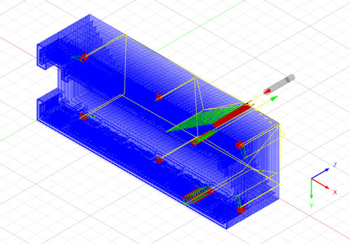
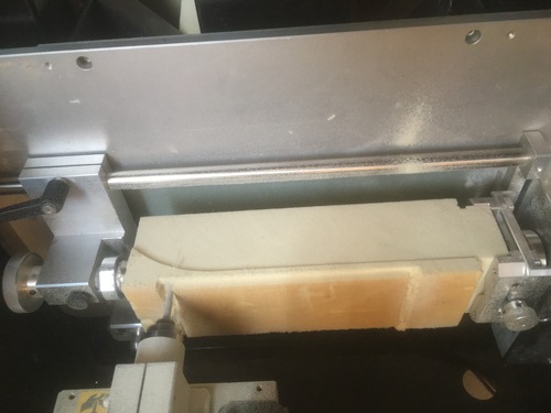
The second job was identical to the first, but tool orientation was rotated by 180° around the A axis, in this way I machined the second side of the model.
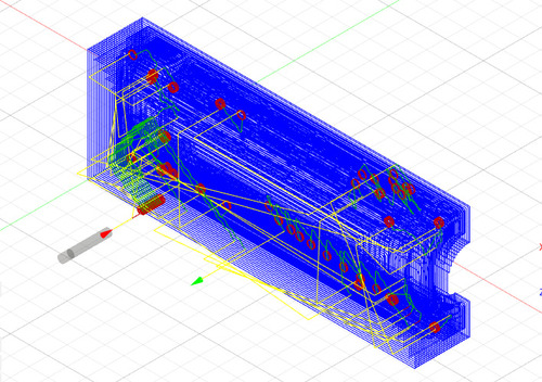
The third job was the first rotatory milling, it was also done with the 4mm flat mill. Most options were similar to the previous jobs. The job lasted about 10 minutes.
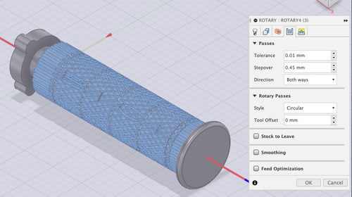
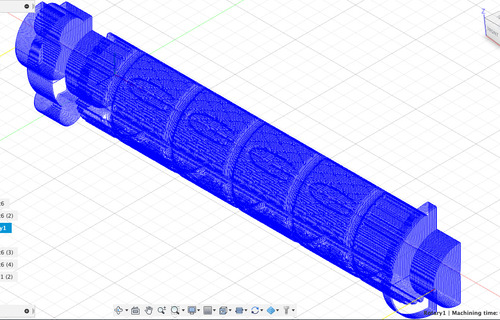
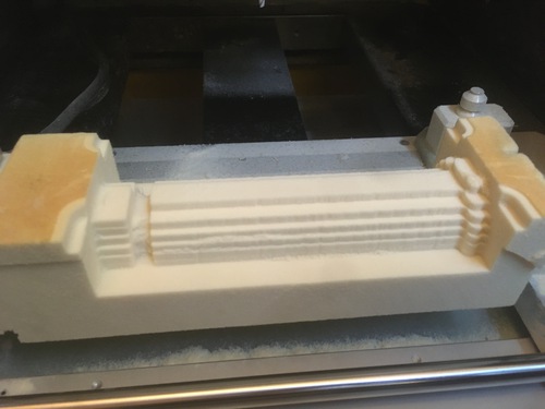
Fourth job was another rotatory milling (circular tactic), this was done with a much smaller mill bit, this was the first finishing job. All the consequent jobs were done to better “define” the detailing. In these jobs I did not machined the whole surface, but solely the parts where I needed the most details, in order to speed up the process. This job took about 35 minutes.
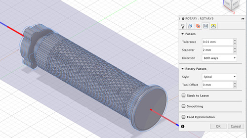
Fifth job was identical to the one before, with spiral tactic instead this time. Changing the tactict maintaining the rest unchanged alloed the mill bit to reach different surface areas. This job took about 15 minutes.
The sixth job was the most detailed as it used the smallest mill bit and the shortest stepover, this job was done to obtain the most details in the knurling and engraved letters. This job lasted about 35 minnutes.
The last job of about 3 minutes, took out the reamining stock to leave left on the extremities.
Second model CAM
As it happened for the CAD, the second model came with a much quicker CAM. One learns from their mistakes, otherwise it would make no sense to make mistakes at all.
The second model is actually made by two separate parts: meaning I did chage stock halfway through. I was very good to find out that I could start by designing one unitary body, that I then split.
There were two separate setup, even if identical (aside from the model body), as they both shared the same origins and stock sizes.
If in the first model it took 6 jobs to reach the final wanted result, it took exactly half for the second model. This mainly because I noticed I could avoid all the middle passages, and, after the roughing pocket clearing. I could go stright to the detailing job, done with the smallest mill end. The total machining time came to be much shorter than half (even changing stock midway through), as there were not only much less jobs, but also 2 tool changes only.
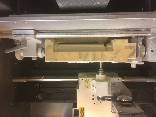
Machining
All the machining was done on the loyal Roland MDX-40 with the addition of it’s forth axis module.
These were the mill end I used for the jobs:
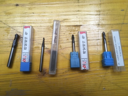
I had bigger ball end mills for roughing and smaller bits for finishing and details.
- 4mm, flat end mill; for roughing
- 2mm, ball end mill; for finishing
- 1mm, ball end mill; for detailing (I told Fusion this was 0.9 in diametre for the CAM to allow for deeper machining)
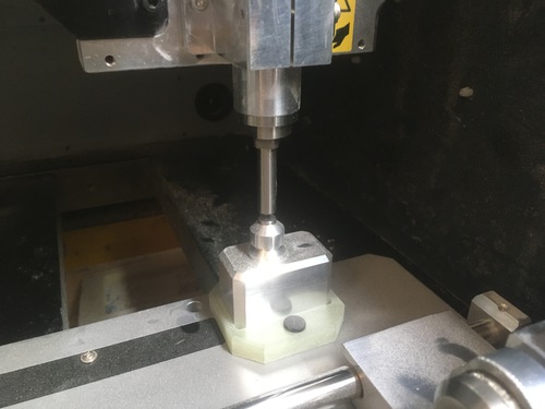
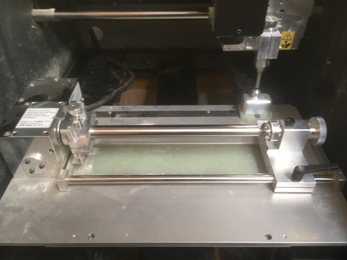
Machine setup
Our loyal Roland MDX-40 has a rotatory axis expansion. To install it you have to unbolt the sacrificial layer and substitute it with the rotary axis system, you then have to pull its cable and the jack connector to the back of the machine and slot it into the correct port.
You then have to install the detection pin, which is used to probe for the Z origin.
Once the detection pin is installed, one has to follow the steps on Vpanel to execute the detection routines.
Secondly the A (rotatory axis) origin is to be set, this is done by rotating manually on the VPanel app the rotating body, so that the tightening know is on top o the A axis.
The third step to be done is the detection of the centre of rotation. You first have to install the detection bar and the detection pin. When the tailstock and tightening knob are in the correct position and solidly tightened, it is possible to start sensing.
Once these steps are done is possible to start preparing the actual stock and tool used for the machining.
The stock, whatever its shape is, has to fit inside a imaginary circle of 120mm diametre. Its lenght has to be under 270mm.
One more thing to take into consideration in terms of stock selection is that one side has to be inserted in the vise, that is as wide as 45mm.
There are also limitations in terms of tool extension:
-
its maximum stick-out is 43mm.
-
one has to check that, with the spindle moved to it’s maximum Z the tool itself is still higher than the rotational range of the workpiece
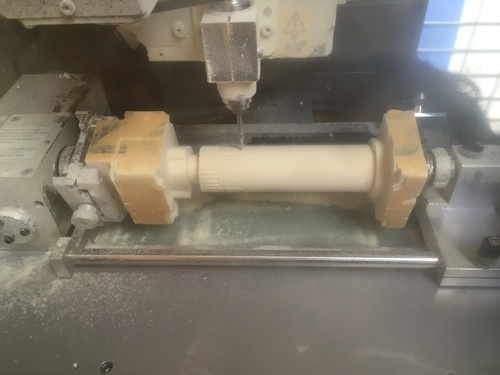
Once the stock and tool are installed, you can procede to set the Z axis again, this time not using the detection pin but the mill tool itself.
As the A origin was set before, and the Y axis corresponds with the central axis of the stock, the only one origin left to be selected is the X origin, this is done manually on VPanel. The one thing to be taken in consideration, is that the tool has to avoid stiking the centre vise.
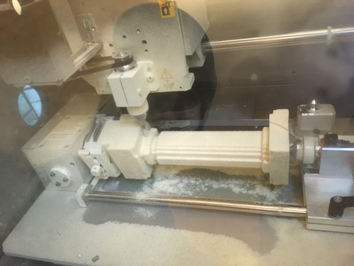
First Model Machining
The machining of the first model was done in a series of jobs:
- first side roughing pocket clearing
- second side roughing pocket clearing
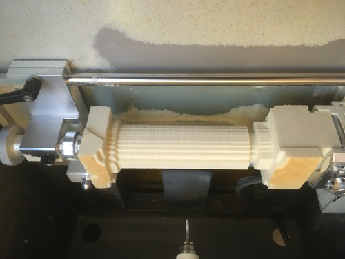
- roughing rotary job
- finishing rotary job
- detailing rotary job
- finer detailing rotary job
The reason why I choose to run so many jobs is that as opposed to normal 3 axis machining I found it easier to locate the origin and change tool, as well as the fact that I was working with very soft foam, which allowed me to run the jobs at the maximum speeds available on the Roland. On top op that gradually reducing the size of the end mill allowed me to control the state of the detailing, deciding step by step wether to contnue with further machining or be satisfied with the current state of the finishing.
On top of that, I realised that my end mills would be able to access different areas of the model depending on what tactic was being selected (circular, spiral, parallel).
First model post processing
I decided to cut the model by hand and, once I could hold it, I was very satisfied with the result.
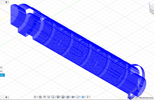
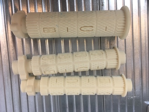
Machined Models
Here is a picture showing all of my handlebar grips positive model.
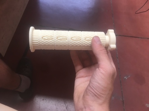
Details on first model.
Details on second model.
3D Printing
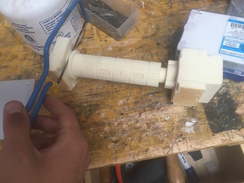
I 3d printed the a jig for the internal diametre, this was supposed to be inserted in the golden standard, in order to create the negative space for the handlebar.
Casting and moulding
This was the step were this project started to really have some issues.
Casting and moulding is surely a complicated, messy, sticky process, for which you can attempt to reduce your margin of error, or to improve once ability to perform this process, BUT it still may lead to unfortunate resuls. As it happened in my case.
First model golden standard
In order to obtain a golden standard I decided to build a jig, in which the model would be inserted using the side presenting the locking mechaninsm. Once the mould would have been set, it was to be cut in half, the model to be sobstitute with the spacer for the internal diametre. The resulting casting box would have been kept together by a new box and filled with the final silicon of my choice. Unfortunately for me, very little of this actually happened.
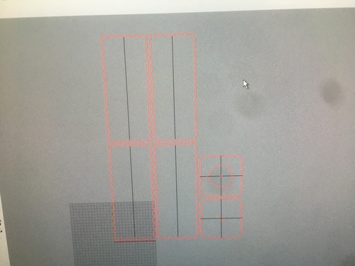
I first designed the jig on Rhino.
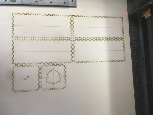
I then laser cut the jig and assempbled it.
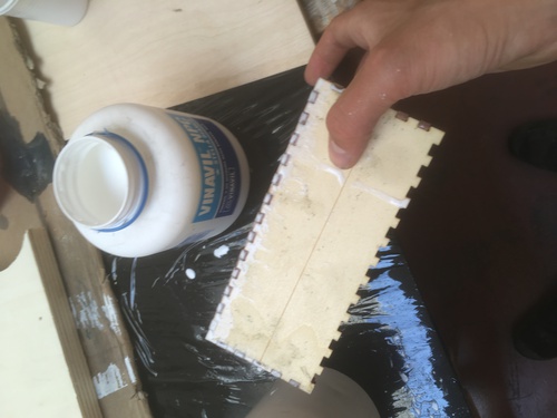
I used vinylic glue to better seal all sides.
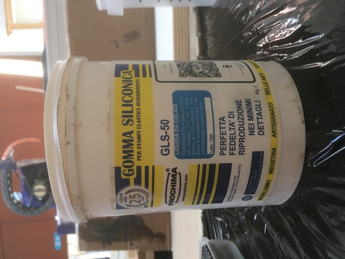
I used a silicon with a 1:1 ratio between the 2 components, this silicon presents a fairly elastic shore value, allowing me to be able to remove the model after the curing time has ended.
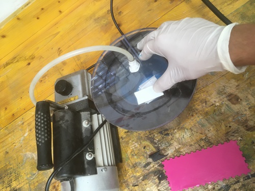
After I weighted the two components, pour them together and mixed them, I decided to try and degas them. I used a vacuum chamber.
Unfortunately, I did not know that this process would massively impact the curing time.
As a result, while I was slowly pouring the Silplay, the mixture quicky becama increasingly viscous, to the level that the mixture wouldn’t flow on itself and on the model’s surfaces.
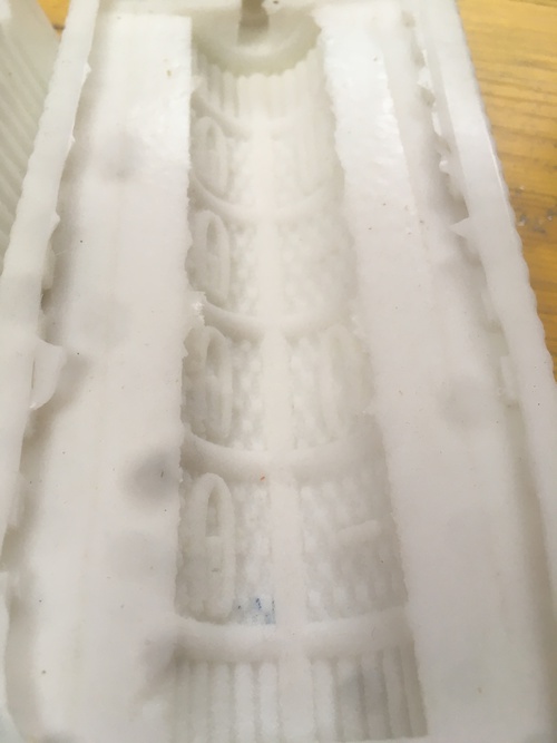
I still let the silicone to fully cure before retreiving the model, so to evaluate how the golden standard would come out.
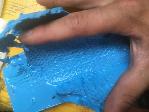
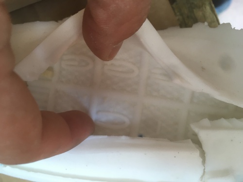
I was quite happy with the level of detailing.
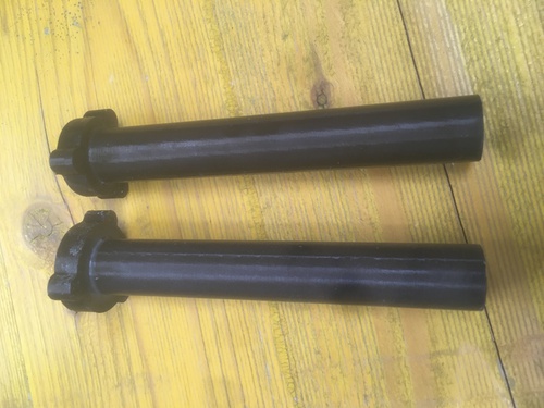
Second model golden standard
This casting\moulding process was supposed to be easier: it would not need a jig, the model was not suspended mid air, the filling\air leak channels were easily doable by just using plastic straws (still a legal item in Italy!).
I messed it up nonetheless.
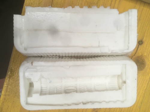
I did fixture my models to a wood base using double sided tape, but in one of my models the mixture detached my model from the stock, this made it impossible to take out the model or to align the two halves in order to pour the final positive.
I was sad this happened as I thought the detailing had come out pretty nicely.
Future Iterations
At this very moment the kind of 2 parts materials I need to re-do my golden standards and ultimately to pour my finals models are hard to get hold of in Italy. I will probably wait for the end of summer, oping the production and logistics line will be fully operational by then. I will probably try and machine a second model for each grips, so to be able to cast a full set each time. I will do a little pre-order of these handlebar grips through the cycling club I opened called GGGG.bici, once I will know more or less how many I will need to be producing, I will be ordering the materials, with part of the money raised with the preorder. I plan to sell these grips for about 20 euros, but giving the possibility of receiving a free replacement in case the grips fail withing the first year of use. I will also give a 30% discount to every consequent pair if somebody buys more than 1 pair.
As this project started as a way to experiment with the rotational axis (I was the first in the lab to fully experiment with this module!), but continued as a small out-of-academy project I did not want the lab to spend money on something I would have made profit from, therefore, once I finished the remaining silicon in the lab, I decided to wait untill available to the general public to finish this project.