Final Project
My final project is meant to be the coming together of all the skills and notions I learnt through the course.
The artifact I decided to design and produce is a chess clock.
Why a chess clock?
There are two main reasons.
Some friends of mine have been organising amateur chess tournaments on Thursday evenings. The are called Blitz at 6. They are lovely persons so I thought I could make this timer and gift it to them. Maybe they will allow me an extra pawn on the field, but I doubt it.
The second reason is strictly sentimental\conceptual: I do not play chess anymore, not competitively. But I used to play. Since I was six, untill I was 10, I used to play weekly. That is an age during which you encounter a very steep learning curve: you start primary school, and from then onwards, you continue learning. I did feel extremely empowered from all of this learing, and playing chess made me feel clever and proud. I did not feel in the same way, untill I started the FabAcademy. When I began this course I felt the same excitement I felt when I was learning how to read: it is a different kind of acquired literacy, but the fabrication and coding knowledge I got from this course feels as useful and as important as when I learnt the rules and symbols that form human communication.
Therefor, when I started thinking about my final project, I wanted to reference in some way that period of my life. A little wink to the past, kid-Filippo from the current semigrown-Filippo.
The Clock
Here I am going to outline the features and characteristics of my chess clock.
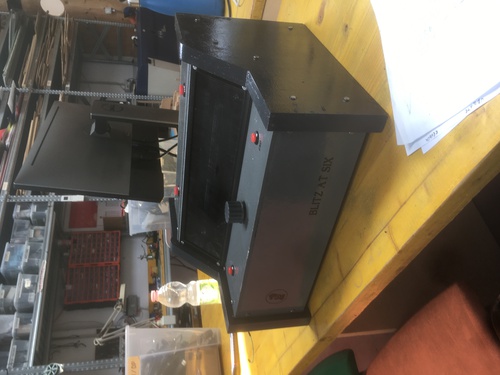
Structure
The structure itself is inspired by the looks of cold war era equipment in the navy and aviation, it was also inspired by the looks of Moog synth: such as the Minimoog, or the Subsequent 37.
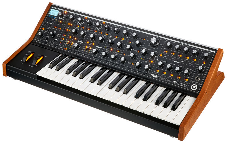
This Flickr album was of great surce of inspiration.
The machined plexiglass screen is meant to hide the looks of the LED matrixes, and is supposed to help convey the feeling of this object as a retro-yet-futuristic piece of equipment.
I decided to opt for a much bigger, heavier and sturdier structure than the usual chess clocks. I had a series of reasons for this:
- I wanted the clock to feel “important”, and something heavier and bigger is generally percieved like that in western cultures
- I wanted it not to be a portable object: I envisioned it as permanently waiting to be used, sitting on a small table, overlooking a chess board
- I wanted the players to feel they could hit the buttons and the clock with quite some power when passing turns, I do enjoy the sound of a palm slapping the wood or the plastic buttons in the adrenalinic peaks of a good game.
The two machined wood sides hide the joints that keep the rest of the faces. Each panel was laser cut, and aside the front, back and bottom panel, the other three carry a function: the 2 flat faces present the buttons and rotary encoder, while the screen is inclined by 45°, so to help sitting players to properly see their times.
These panels hide the connections, the boards and the power supply of my clock.
Features
The clock has a screen of 256 LED pixels distributed in 8 rows for 32 coloumns. This screen is covered by a machined plexiglass piece.
There are a series of buttons in this objects:
- left player button
- right player button
- mode\reset button
- start\end button
There is also a rotary encoder that has a push button function, which makes it the 5th button on my clock, used to select values.
Functioning
The clock has several functions:
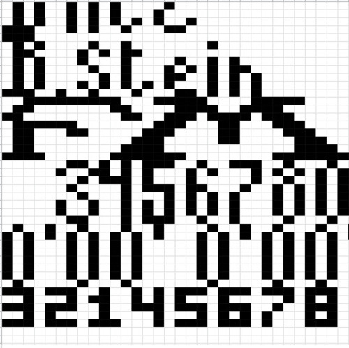
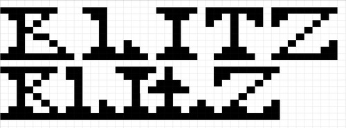
- it runs an animation stating my initials and the name of my chess playing friends’ event: Blitz at 6
- it then allows for you to select among various time control modes
- it gives the possibility (depending on time control rules) of selecting available game time to players, available moves to players and delay\increment values for each move
- once the game has started the time does not start running unless one of the two players begin their first move
- there are various triggers for the endgame: the time may run to 0, the move may run to 0, the players may press the endgame button
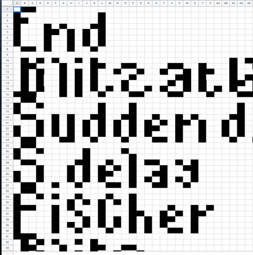
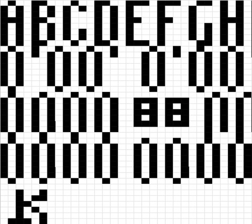
The clock also utilises a bitmap font of my design.
Design
As I mentioned before, my references for the looks of the clock were quite clear. To know pretty much how something will have to eventually look saves a lot of time: you can deductevely find out what production processes you will need in order to achieve such look.
Thanks to all the prior months working with the softwarea and the machines, I knew what I would need to do to reach what I wanted to do. The main factors that made me opt towards an option or another were most of the times quite practical:
- how long will this take?
- can it be done at the same time of another task?
- how much waste will it generate? can I have multiple versions on the same stock?
and so forth.
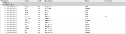
All the design is parametric so it can always be adapted to different screens, buttons, screws, wood stocks and so forth.
Most of my design was done in Fusion 360.
The whole design is done with parameters.
### Joints
The 3D printed joints were the first element I designed.
It was easy to imagine the sides and panels (being simple rectagles at a certain angle), but not how they would have been kept together. I so started my design from the joints.
These would have needed to be produced additevely due to the complex shapes, overarches and holes: 3D printing was the way to go.
I also found that in terms of fixturing, 3D printed materials to not always need bolts when prototyping if thick enough, as they slightly melt, adding friction that keeps the structure together.
I only needed to design one set of joints and mirror them, on top of that the 2 sets of 90° joints where almost identycal, only differing in height.
Joint features:
- The central joint holds the screen at 45°, and it’s designed so that the screen and sides meeting point is hidden
- joints holding the bottom face would differ from the other sides as they weren’t enclosed in the sides, so that the bottom face could be taken away for quicki re-wiring and degugging
- the joints would allow for the central structure to be solid even without the sides for increased stability and the possibility of prototipation prior the end of the sides’ machining
- asymettric holes positioning for bolt screwing clearance
Joints CAD
All joint design was done in Fusion. It was done in two iterations:
- the first version had holes placed at the geometric centre of the face where it was needed, this would cause the bolts to meet at a certain point, preventing me to tighten them fully.
Joints CAM
The file for the printer was generated in Ultimaker Cura. In my first design I put 50% infil and thinner walls, as well as higher layers to speed up the printing, while I was milling boards. The second design still presented 0.2mm layers for added friction with the bolts as I was not bothered with the looks, being the joints an hidden component. I differed with the first print in terms of infill density (now 90%) and wall thickness (now 3mm instead of one) for added rigidity and adhesion with the bolts.
Joints production
As described in the 3D printing assignment. Nothing special to make note of.
- retreiving the second version of the joints after printing
Panels and screen fixture
The faces\panels were easily done with laser cutting: they only presented 2D features (cuts, holes), I wanted them in light and thin stock. On top of that the laser cutter is one of the quickest machines (if one avoids bitmap engraving) both in terms of operating and operational time.
Panels CAD
I also designed these in Fusion 360. Holes were projected from the joints, all other dimensions were arbirtary, proportional to the screen, and functional to the sturdy final look I wanted to acheive. I also had other holes were I wanted my buttons to be. The matrixes fixtures holes were based on a 3D model found on Thingiverse, unfortunately now taken down by the original author. THe holes for cabling were enlarged toallow for better clearance and my clumsy manners.
Panel CAM
I exportend the sketches of the panels faces as DXF. Imported them into Rhino 7, in order to scale them (as sometimes moving between programs alters the dimensions), place the design into one layer so to facilitate the printing process and export them to Rhino 5, as the computer connected to the laser cutter has that version of the software.
Once in Rhino 5 I opened the laser cutter extension, nested my design, ran sum speed tests, and was ready to cut.
Panels production
Pretty much as described in the computer cutting assignment. Nothing particual to mention.
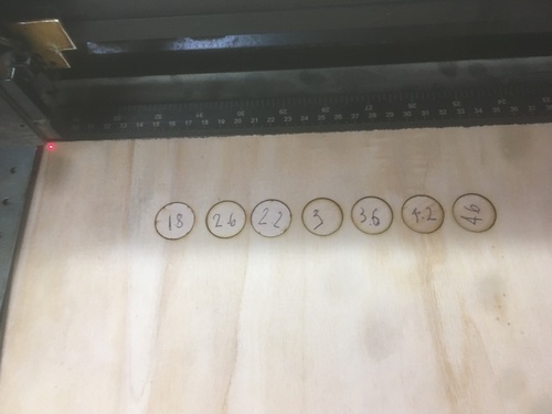
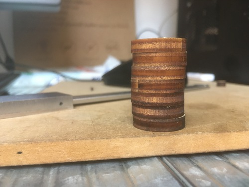
- laser speed tests
- clearance for wires on the screen fixture
- panels lasering
Screen
The plexiglass screen was also designed in Fusions.
It had a variety of features:
- filleting to allow for mill bit clearance
- holes for fixturing
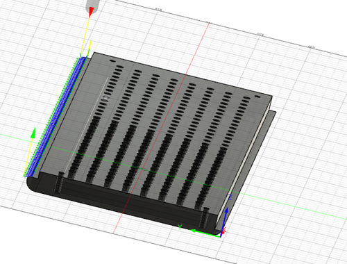
- drill holes in the back, projected from the LED placement to channel the LED beam preventing the halo effect
- a pocket clearance on top to reduce the material thickens where the screen is
- its sides were designed so that they would hide the meeting point with the panels
Screen CAD
The screen was designed in Fusion 360 proportionally to the matries model.
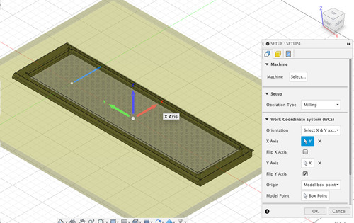
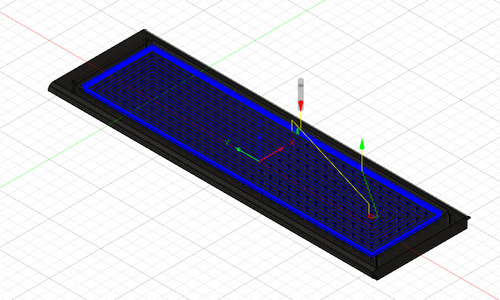
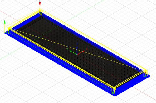
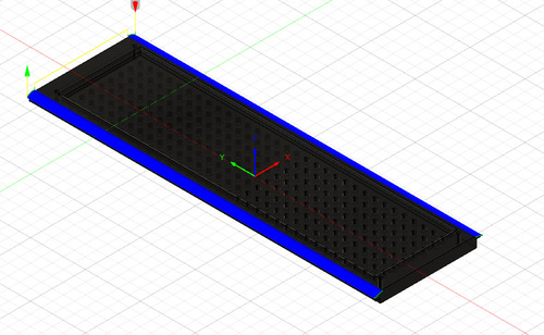
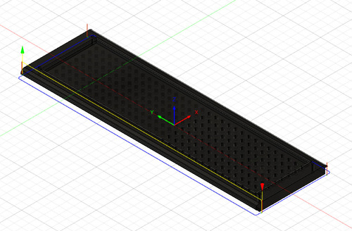
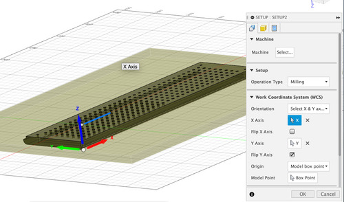
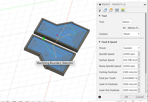
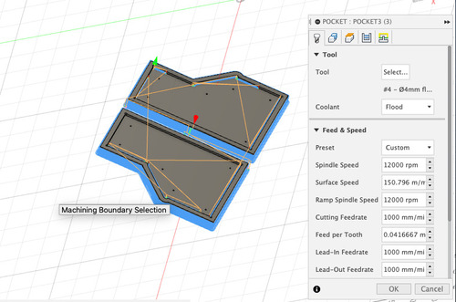
Screen CAM
This part of he process also happened in Fusion 360. The hardest part in the CAM for the screen and it’s production was setting the origin system and model orientation. This was caused by the fact that I would have to oprate different set of jobs on each side, mantaining the same machine origin (aside from Z axis, which is instead tool related), so changing model orientation.
All feeds and speeds were very reduced (especially for drill jobs) in respect of normal wood, as plexiglass is extremely hard are risks too melt once the mill end gets too hot.
- alignment jig setup
- screen top side setup
- fixturing drill holes
- pocket clearing jobs
- filleting
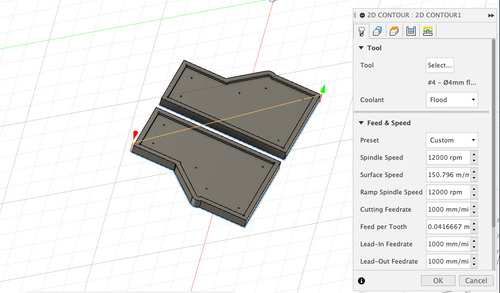
- contour
- other side setup
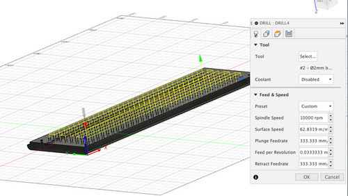
- partial drill holes for lights
- pocket clearing
- filleting
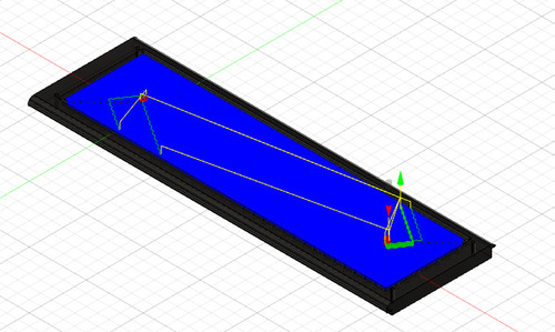
Top side
On this side I had 3 Jobs:
- drill holes for fixturing (both while machining and in the final assembly)
- roughing pocket clearance for the inside and the outside
- finishing pocket clearance for the inside and the outside
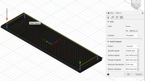
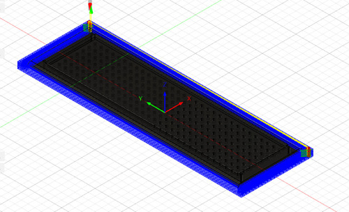
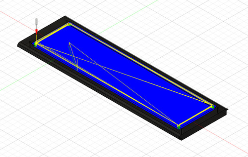
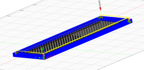
Bottom side
On this side I had 3 Jobs:
- drill holes for LED light
- roughing pocket clearance for the the outside
- finishing pocket clearance for the outside
- phantom job to check everything was correct
- drill job, I used partial retract to reduce tool overheating and stressing
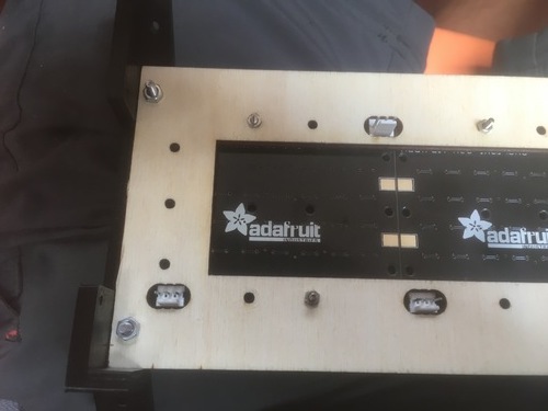
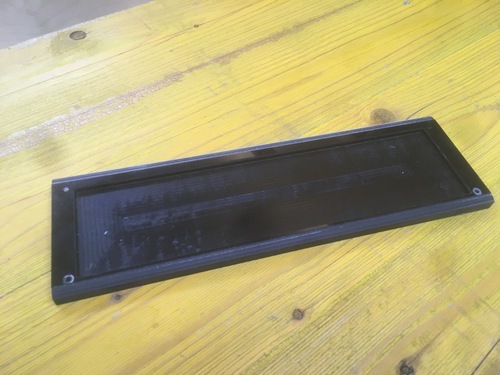
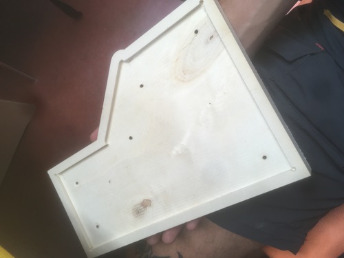
Screen production
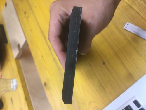
I used the large format Shopbot CNC machine for the production of the screen. I used 10mm thick black plexiglass for this screen. I fixtured the stock to the machine and proceeded following the workflow outlined in the CNC assignment.
I’d say the aspect that was the most worth noticing is that I smelled melting plasting when drilling so on top of overriding the current rpm settings on the shopbot I sprayed some water on the stock (keeping all de distance from the spindle).
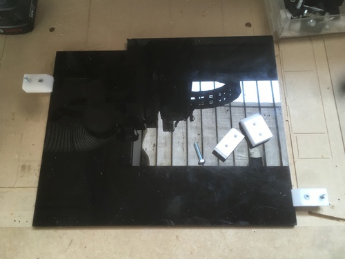
- Fixing the stock
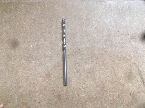
- Drill bit used for fixturing holes and back light channels
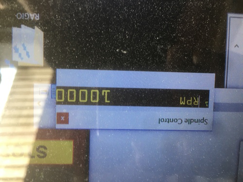
- RPM override when my drill job was too quick (causing the plexiglass to slightly melt around the edge)
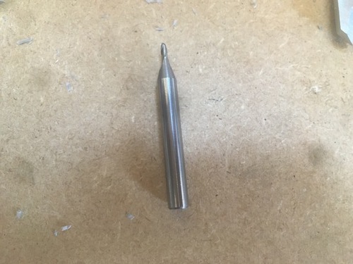
- Ball end mill used for finishing jobs
- final results
- roughing pocket clearing on bottom side
- finishing pocket clearing on bottom side
- roughting external pocket clearing on bottom side
- contour job for alignment jig
- external finishing pocket clearing
- filleting
Sides
The two thicker sides, inspired by Bob Moog’s synths, kept the structure together.
Sides CAD
The sides presented a pocket clearing on the inside to hide the point of meeting of panels and joints, the bottom panel is intead free to be removed for prototyping.
I only had to design one as the other one was mirrored.
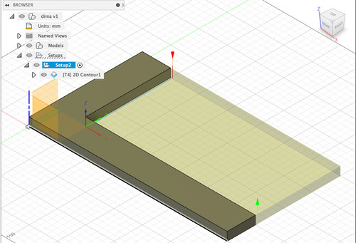
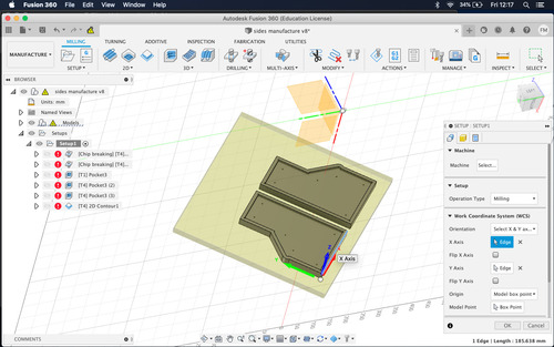
Sides CAM
These parts of the structer were also manufactured with files made on Fusion. Luckily for me I did not have to flip the stock as all jobs were on one side.
I had several job for these components:
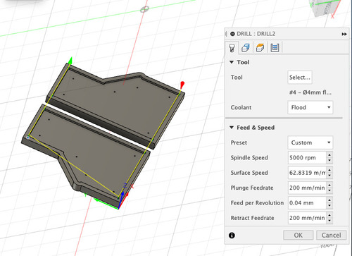
- drill job for fixturing (both for the machining and the assembly)
- roughng pocket clearing inside and outside
- finishing pocket clearing inside and outside
- contour job to detach the shapes from the stock
- setup
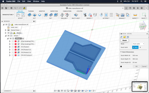
- stock selection
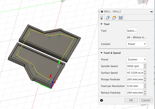
- Drill holes
- Dogbones for sides sitting
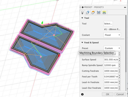
- roughing and finishing pocket clearing
- contour
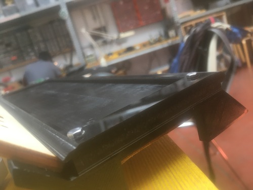
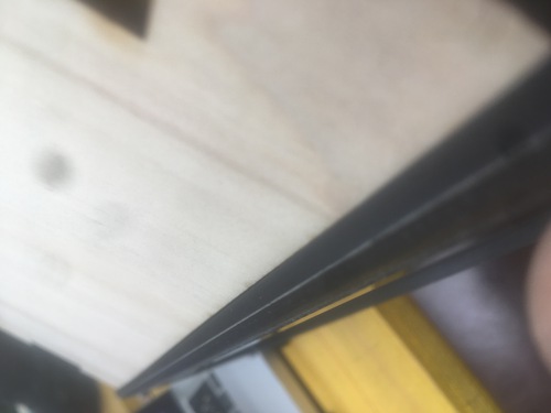
Sides production
I used the large format Shopbot CNC machine for the production of the sides. I used 20mm thick mdf wood for these parts. I fixtured the stock to the machine and proceeded following the workflow outlined in the CNC assignment. In order to keep my origins when flipping the board I machined a small jig with a precisely machined 90° angle, that I used as reference to fixture the screen once flipped.
- final result
- sides holes drillling
- roughing pocket clearing
PCBs
I had two PCBs for this project:
- the main one would receive all signals from the buttons and rotary encoder
- it would also to the processing of the time and the setup of the game
- the secondary board would recive inputs from the first board via i2c, these would
- cause the board to render on the LED matrixes a certain bit array
- cause the board to show each player available time on screen
I also had a series of breakout boards:
- one to spread power supply from the cable to the matrixes (with a 1000kU capacitor) and to the i2c board
- one that would supply power two the two boards and function as i2c bridge
PCB CAD
I designed all my boards on Eagle. The design followed the DRCs and workflow described previously during the electronic production week.

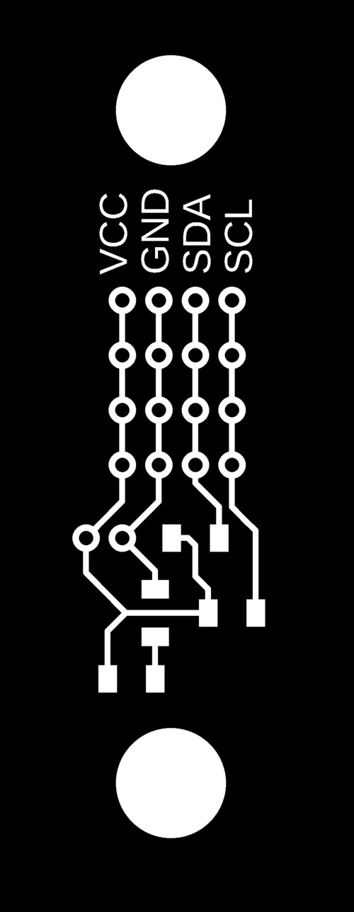
- I2C + boards supply connector

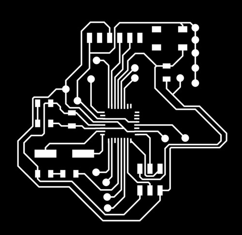
- Main Board

- power supply + capacitor connector

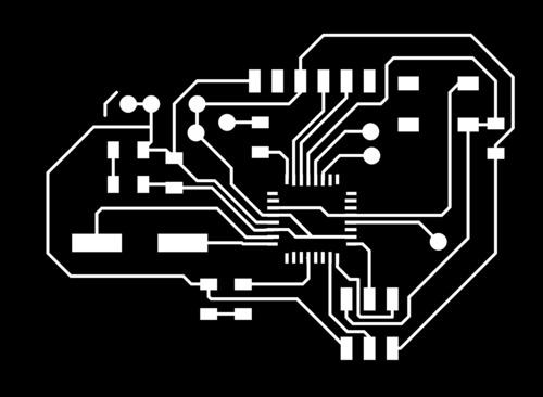
- secondary board
PCB CAM
I did my .rml file for milling o FabModules as I previoulsy did.
PCB production
Nothing special to notice in this part of the process either as t went smoothly due to the skills gained in the use of the Roland MDX-40, most likely my favourite machine in the workshop.
The only thing worth noticing is that, because of problems with the re-supply we had finished single layer stock, but, as I had through hole pins, I had to fully get rid of the conductive layer on the other side, I did so with a brutal combo of a sanding machine, the dremel and a coloumn drill.
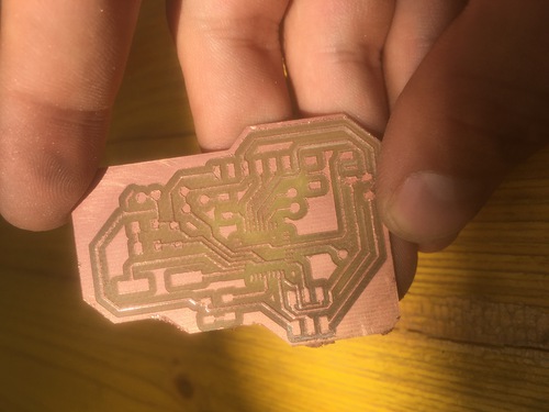
- secondary board milled pcb
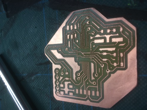
- primary board milled pcb
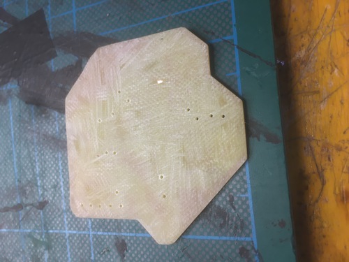
- the aforementioned brutal sanding job, sorry mama for I embraced the dark gritty side of digital fabrication
- PCB trace engraving
PCBs hero shot
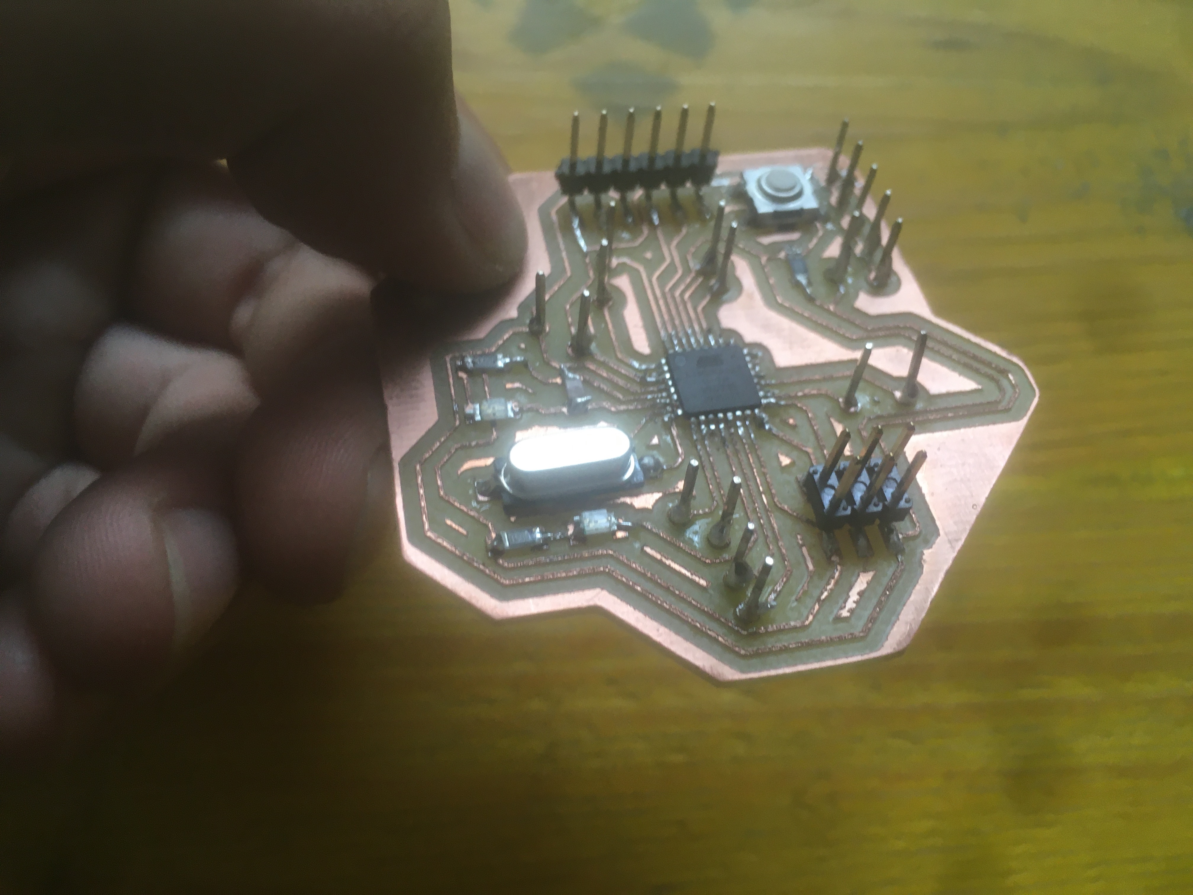
This is my main board, in which the clock will exist.
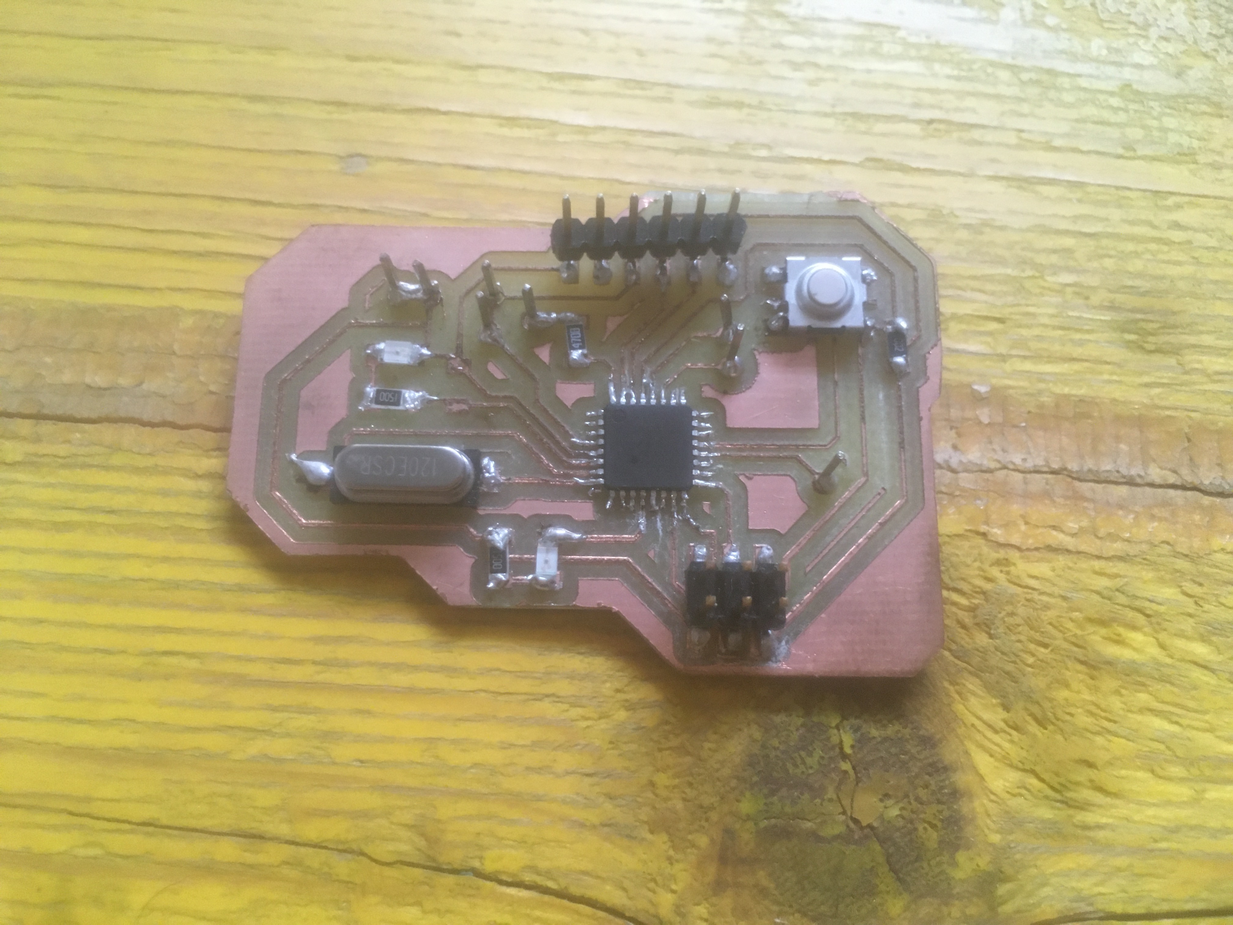
THe secondary board, that will render the main board messages to the LED screen.
Decals
I added vinyl cut details to my design. The structure was meant to present the button function for each button, the name of my friends’ chess event, as well as their logo, and my initials, to stroke my ego.
Vinyl CAD
The logo was designed by my friend Yuri Kaban, one of the two organizers of Blitz at Six, the rest of the writing was designed on Illustrator, using the beautiful Eurostile font family. The font was then converted into shapes and exported as .svg.
Vinyl CAM
I moved my .svg onto Inkscape, on the computer connected to the cutter. I then opened the file with the Reoland Cut Pro extension. Once I nested my design and fetched the roll dimensions, the file was ready to be sent to cut.
Vinyl production
I followed the workflow outlined in my Computer Controlled Cutting assignment. I cut the shapes, peeled off the negative space, placed a sticker layer on top, peeled the back, was ready to stick my vinyl on the clock.
Rotary Encoder Cover
I hve also designed and 3D printed a cover for the rotary encoder. The design was made so to be 3D printed.
Button Cover CAD
The button cover was design in Fusion 360. The diametre for the rotary encoder to fit had a little added tolerance for it to snugly fit, but to be easily removed if necessary.
Button Cover CAM
I did the CAM for this part on Ultimaker Cura:
- layer height was fairly precise for aesthetic reasons (0.15 for fairly smooth surface finishing)
- infill was 75% in order for the part to feel weighted, but quick enough to print
- button cover printing
Wiring
All internal wiring beween the matrixes, the moards and the breakout modules was done with felame\female jumper wires.
Buttons
I decided not to design buttons but to buy them, as I was starting to run out of time, entirely for my fault.
As I had opted for gray in the looks, I opted for menacing red buttons, definetely adding to the Thrill™ of a game of chess, played with a fabable clock.
Bolts and nuts
I did not have any glue or mechanical joints in my design. I opted for nuts and bolts for fixturing for two main reasons:
- you can rely on bolds and nuts to never fail
- they are quickly installed or removed for rapid prototyping
- I choose simple flat hex bolts, I thought they looked perfect for my project
Painting, Finishing and Coating
The post processing fase was also hindered by my time management: I had planned 3 coats on top of the other, with sanding in between, to achieve maximum smoothness. Because I did not wait long enough for the sandng, some areas presented thicker\bubbly parts of paint. The clear coating added a lovely translucent layer to the clock.
System Integration
I had predicted the inside of the clock would be a bit messy: I have 2 boards, 2 breakout boards, 4 matrixes, 4 buttons and a rotary encoder.
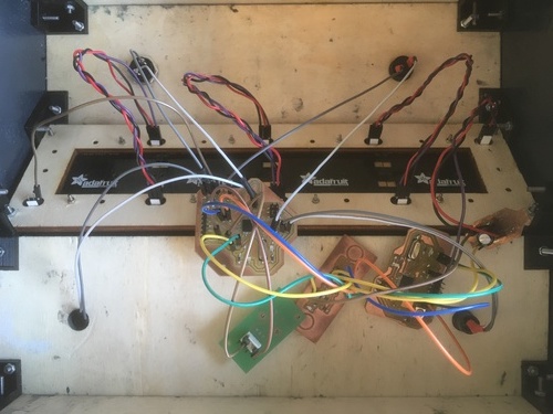
In this iteration the whole connections were made with female\female jumpers. This resulted in a tangle of wires, especially caused by the lenght of the jumpers: if I had them longer I would have managed to put them in braids.
Font & BitArrays
I designed my font and bit arrays (for animations) on Google sheets, It was an easy way to quickly test designed based on binary values, I then copied such designs in value arrays, placing a 1 for lit LEDs and a 0 for dark ones.
Software
I wrote my code in Visual Studio Code as it has a series of features missing in Arduino IDE, such as the split screen view or the quick find\replace function. I then proceeded to program the boards and debug in Arduino IDE.
The code is structured this way; in the main board, after the setup, the loop was divided in three parts:
- input reading, depending on the current machine state, inputs (buttons) are read
- system update, depending on the current machine state, variables are initiated and inputs are engaged, as well as preparing to switch to a previous or following state
- render, where values and characters are sent to the secondary board
The secondary board solely renders values and animations to the LED screen.
License
All licensing informations and thoughts available at this link.
I chose the software to be under Creative Commons CC-BY-SA.
Bill of Materials
The list with all the materials used is outlined here.
Slide & Presentation

Files
Software:
Full Assembly:
Joints:
Panels:
Others:
Decals:
Boards:
- power.sch
- power.brd
- i2c_conn.brd
- i2c_conn.sch
- 328_final_secondary.brd
- 328_final_secondary.sch
- 328_final_main.brd
- 328_final_main.sch