7. Computer Controlled Machining
Once again, a more creative week. These are so difficult for me.
First, we got introduced to CNC and were showed all the nice things you can make out of plywood. Then we were told that we are given a sheet of OSB, not plywood. So, instead of of making something nice, we get to make something “trendy” (read: ugly) with more limited actual use.
Wood industry accounts for about 1/5 of Finland’s export and 78% of land is covered with forests, so wood products are relatively cheap in Finland… so we are working with OSB.
Creating a 3D model to manufacture
First I thought about what to make, and on concept level, I ended up on two ideas:
- Table for 3D printer or side table, mainly the same idea, a bit different purpose.
- Side table for living room
I decided to create a table for 3D printer. More about designing in 3D can be found at Computer-Aided Design week.
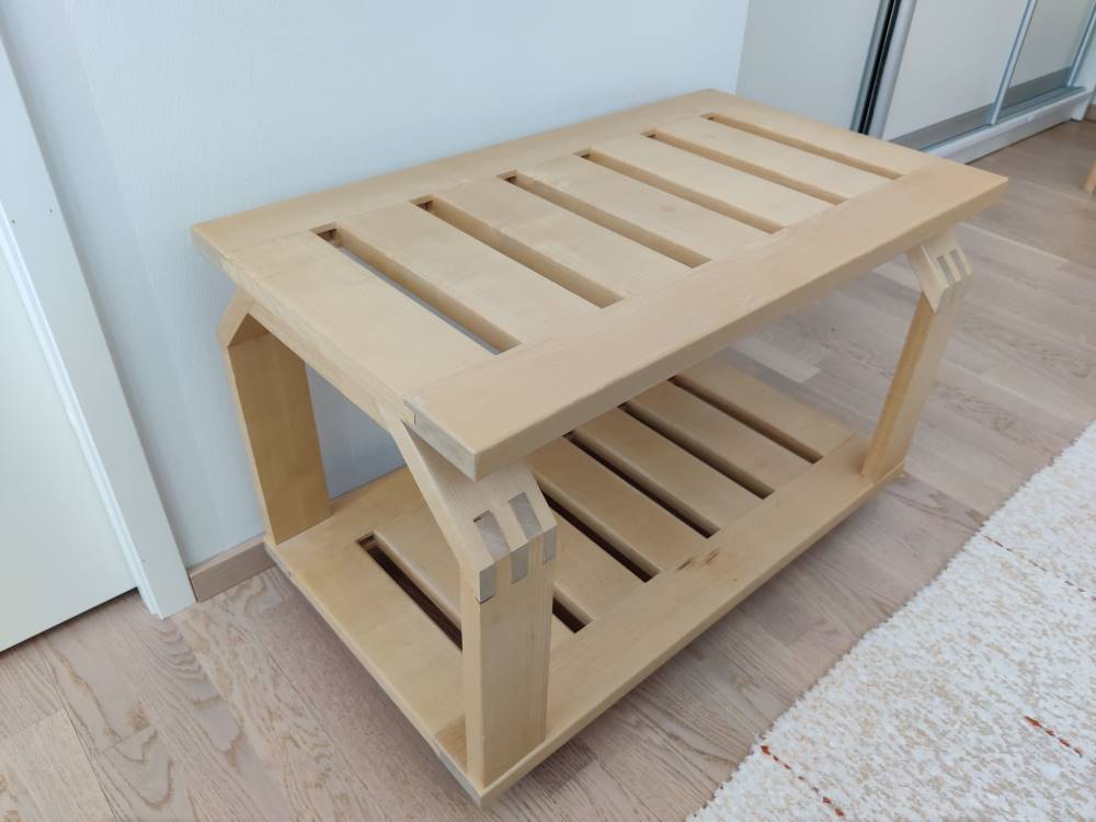
I also visited my parents and got inspired by tables my dad made in 80’s while working on wood industry.
 I designed a more CNC-friendly version of these tables, but when confirming that aren’t we allowed to use Ikea-like wooden pins for assembly, I got denied.
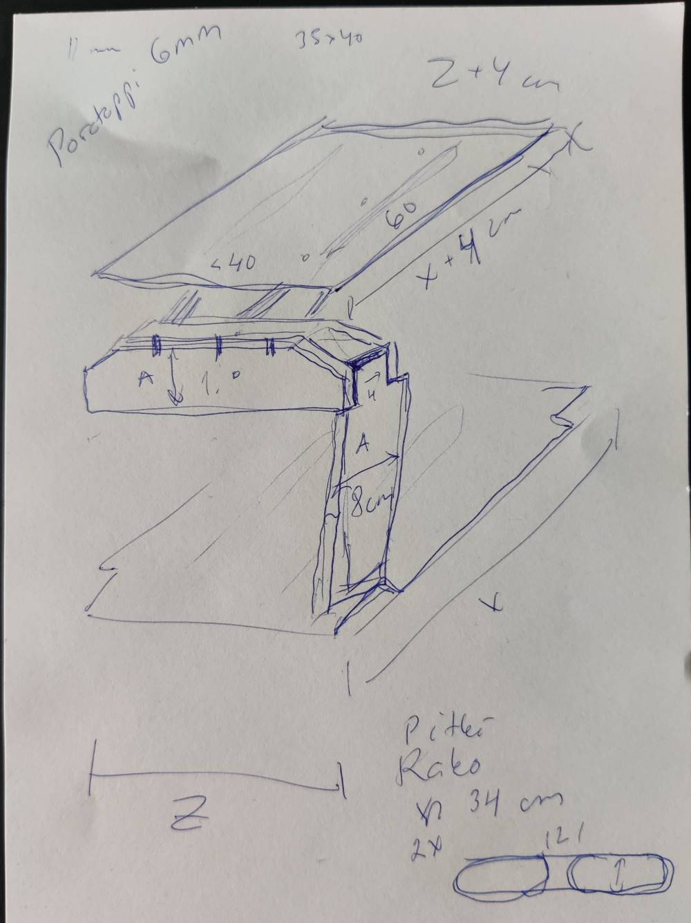
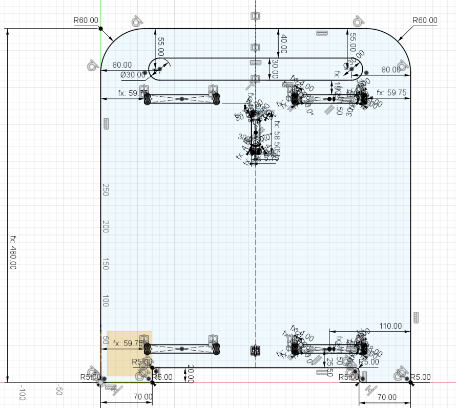
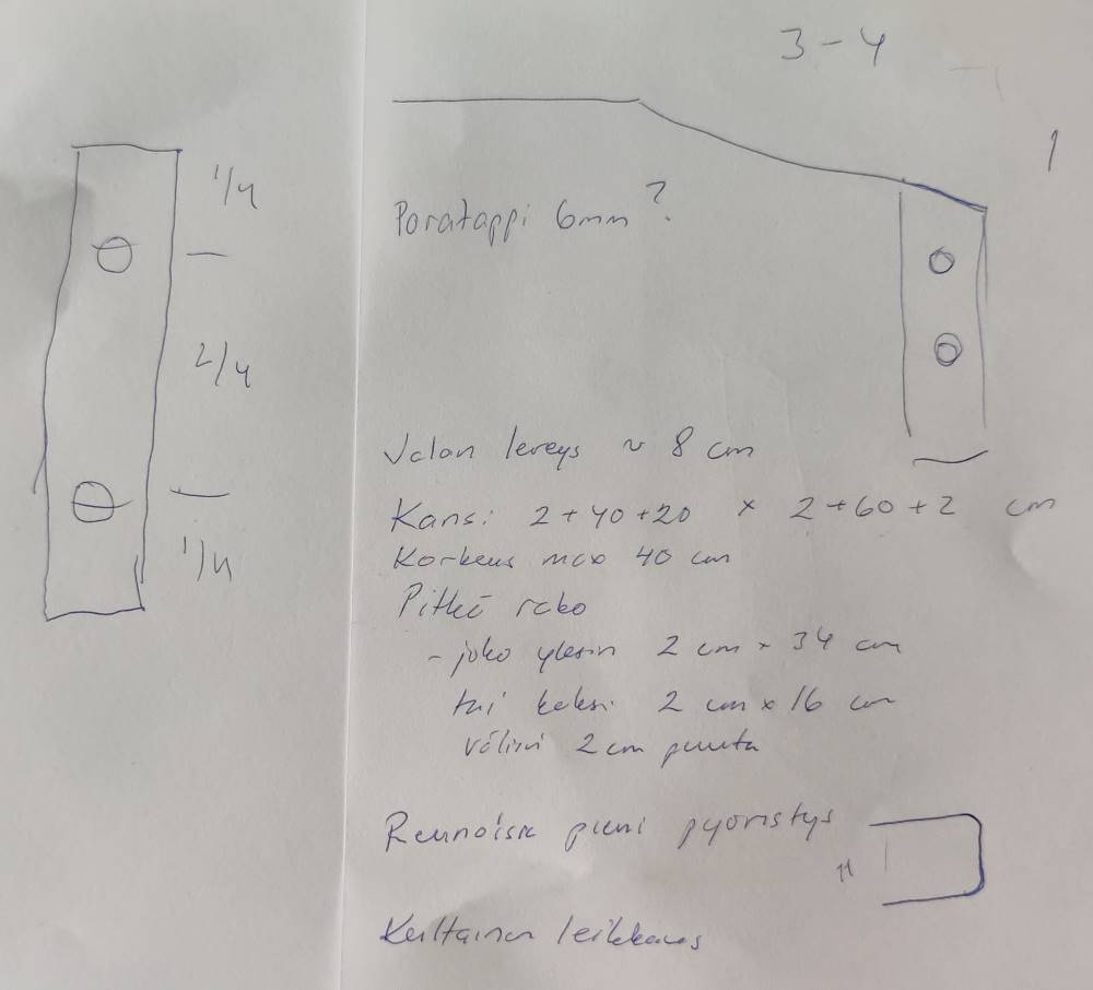 First design had two planes, one on top and one on bottom. Under bottom plane I might use small furniture legs or wheels. Top plane had 2-3 support bars under it to increase rigidity and lengthwise gaps to make it look lighter. Each pair of legs would have an attachment structure under top plane consisting of two bars. Each leg would have a single, wide “finger” on top end to go between attachment bars. Bottom end of each leg would be attached with wooden pins, also the top end of each leg would secured with wooden pins, as would top plane and the attachment bars under it.
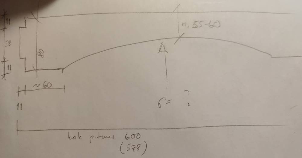
After the denial of use of wooden pins, I browsed around on previous year students pages to see what they have made. Meanwhile, my dad took less than 5 minutes to have a new, rough sketch without wooden pins. We processed the new sketch further together and soon I was ready to launch Fusion 360 and start modeling.
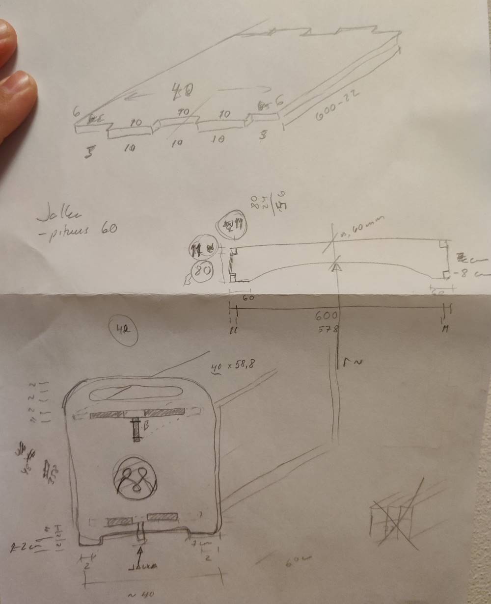
 I got left and right walls ready, but my laptop was about run out of battery, so I had to continue later. Meanwhile, I attended Global Open Time and heard couraging comments of my design, and also some wondering if using wooden pins wouldn’t be against the scope of the week.
Anyway, I kept it simple and got the pin-free design ready the next day. Edit: Adding dogbones postponed it one day further, but other people weren’t ready either, so I had time.
Arranging the design
Something I seemed to have missed on previous weeks, was how to arrange the design ready to be milled. I went looking for previous year students pages and asked help on Mattermost’s local group. Best results I got from Youtube 1, 2, 3.
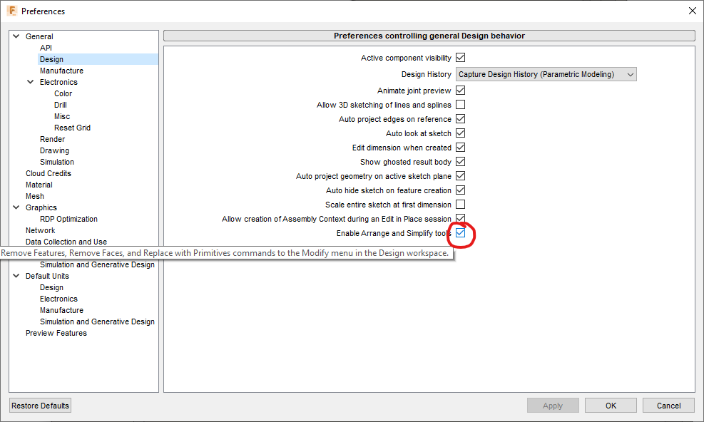
First, I enabled the Arrange-tool.
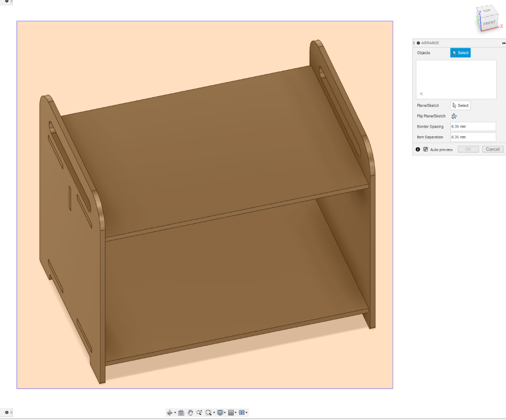
Then I realized the Arrange-tool works on Components, while my design consisted of Bodies. Video 1 helped me with that, and I selected all bodies, right-clicked and selected Create components from bodies and renamed the bodies with sensible names. I kept following instructions on Lars’ video and went to Manufacture workspace, and from dropdown menu of Setup ribbon, I selected Create Manufacturing Model and from the newly-created Manufacturing Model 1 I right-clicked and selected Edit Manufacturing Model. From Modify ribbon’s dropdown I selected Arrange.
Note! In videos the arrange tool is mentioned to be available for commercial users only. I can use it on Education License, but it might not be available for hobbyists with Personal License.
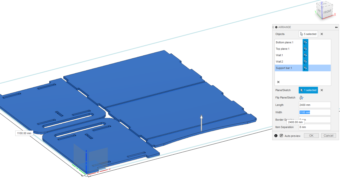
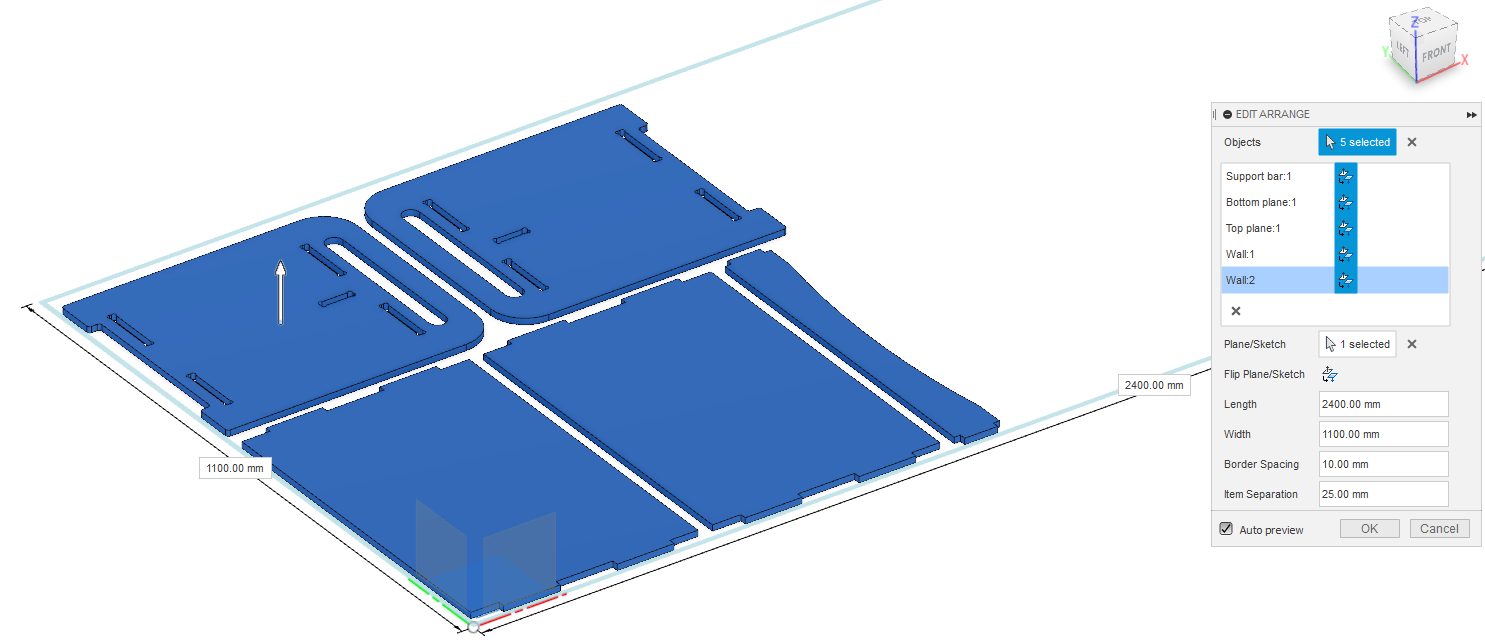
In Arrange tool, I dragged over the design to select all. And for Plane/Sketch selection I chose the bottom plane of the coordinate system (the bottom square next to origin).
 For Length and width I entered the dimensions of available stock, which is 1200x2600 mm, but just to be safe with mounting I entered 1100x2400 mm, which didn’t change the layout.
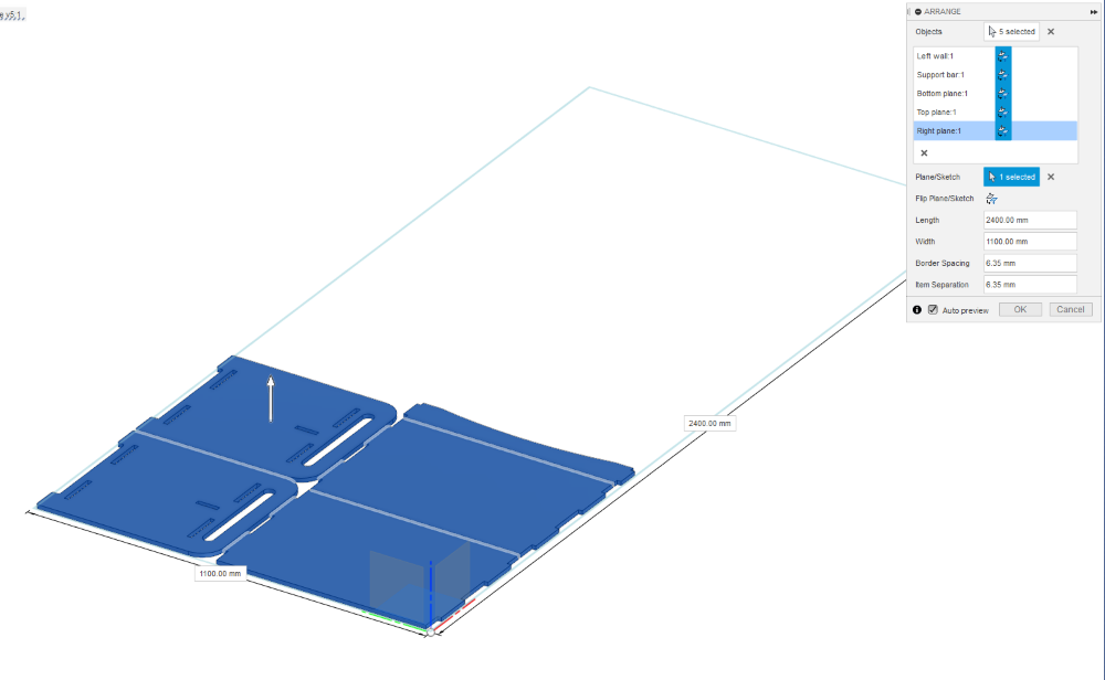 After entering dimensions of stock, the design is laid out on available stock. Now you can edit borders or separation if needed. I just click OK and the design took a second or two to process. Then I was ready to finish edit (button on the top ribbon).
Toolpath generation
Setup generation
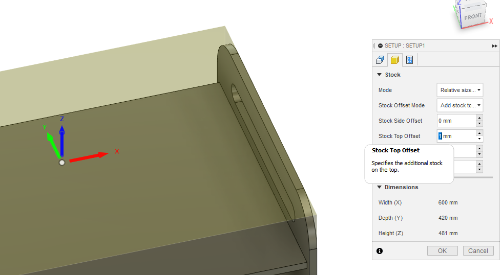
Continuing in Manufacture workspace, click Setup (folder icon with a cube in it). First, zero offsets on stock tab (second tab).
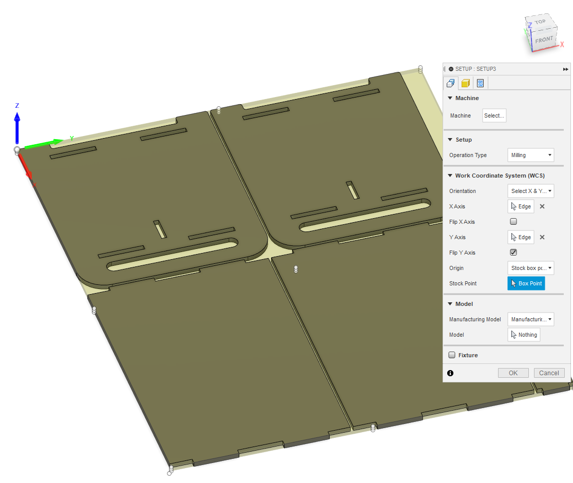
 Back to the setup tab (first tab), click Orientation, select Select X & Y axis, click on X Axis Select and click on width directional edge of arrangement, click on Y Axis Select and click on length directional edge of arrangement. Flip X or Y Axis if needed. Finally, click Stock Point Box Point and select front-left corner on top plane. Click OK to close setup.
Surprise: missing tool library
I was about to try generate toolpath, but following the local instruction video I realized I haven’t set up available tools for local CNC machine. Luckily, Autodesk had a decent help article about it since I was not aware of other guidance about it.
I was confused about all the disabled buttons in Fusion 360 tool library, but all I had to do was to right-click local library and import the tool library available on local Microsoft Teams workspace. (Would it be too convenient to have all information in one place, like Gitlab?)
Back to toolpath generation
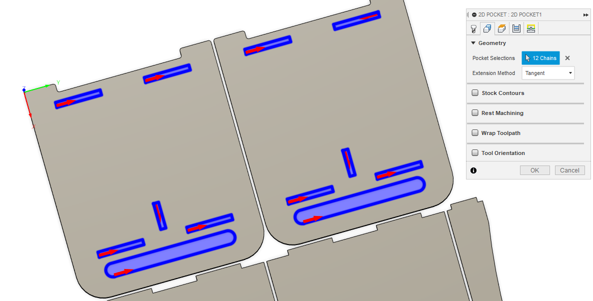
For holes inside pieces, I used 2D Pocket tool and selected 8 mm flat-end milling bit on the Tool tab (first tab).
On Geometry tab (2nd tab), I selected features I want to make.
 On Heights tab (3rd tab), I set Top height to Model Top and Bottom height to Model bottom.
On Passes tab (4th tab), I unchecked Stock to leave and checked Multiple Depths and set Maximum Roughing Stepdown to 3 mm and checked Use Even Stepdowns.
On linking tab (5th tab), I unchecked Lead-In and Lead-Out, and set Ramp type to Plunge and hit OK.
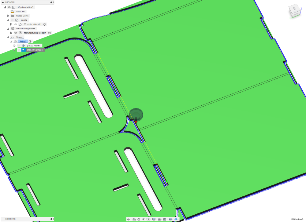
For outlines, I selected 2D Countour tool, used the same 8 mm tool. On Geometry tab I selected all 5 pieces, and checked Tabs, and kept the default values. On tabs 3, 4 & 5 I did same steps as before.
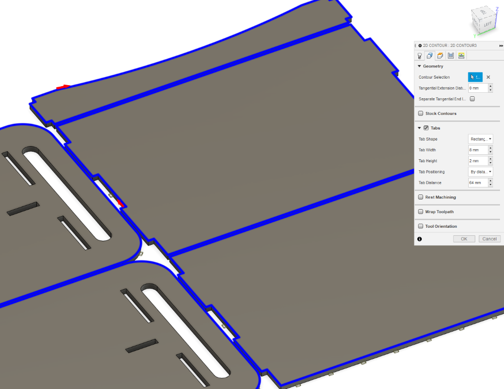
After clicking OK, I can clearly see that selected tool doesn’t fit between the pieces.
Re-arranging after changes
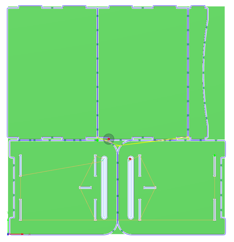
After finding out that design needs to be rearranged so that tool fits everywhere cut separate parts, I also added dogbones to walls. I set Borders and Item separation to 10 mm, so that 8 mm tool has no problems fitting anywhere.
New toolpaths
After adding and editing dogbone slots and rearranging pieces with bigger separation distance, I ran 2D pocket toolpath for pockets and 2D contour toolpath for pieces the same way I did on the first time (read above).
Simulation of toolpaths
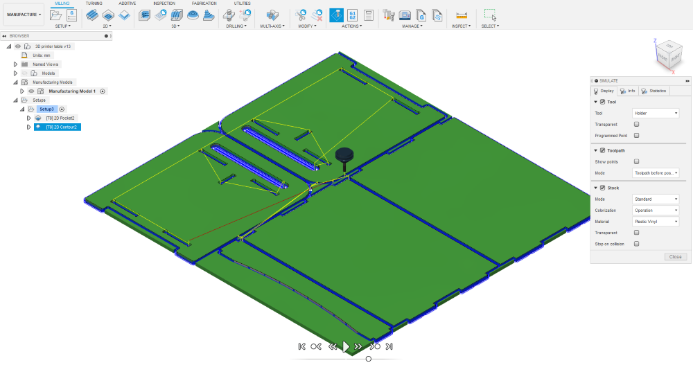
I selected toolpath setup, not just a single toolpath, and clicked Simulate button on the actions ribbon (selected in the picture below), and on Display tab (1st tab) I checked on Stock to see tool virtually removing material, instead of running in holes that appear premade. On the bottom the the window are playback controls and I clicked play to start simulation. Under playback button is a slider to set the speed of simulation.
 After closing the simulation view, I was ready for post-processing.
Post-processing of CNC toolpaths
Post-processing is mainly turning toolpaths into NC-code. I selected all toolpaths and clicked Post Process button next to Simulation button. However second surprise was waiting me there.
Surprise: missing post-processing setup
With no instructions how to setup post processing, it was time to explore once again. Luckily local instructors of some other weeks had thorough documentation about their setups.
So I just selected Use Personal Post Library and copied the .cps file there.
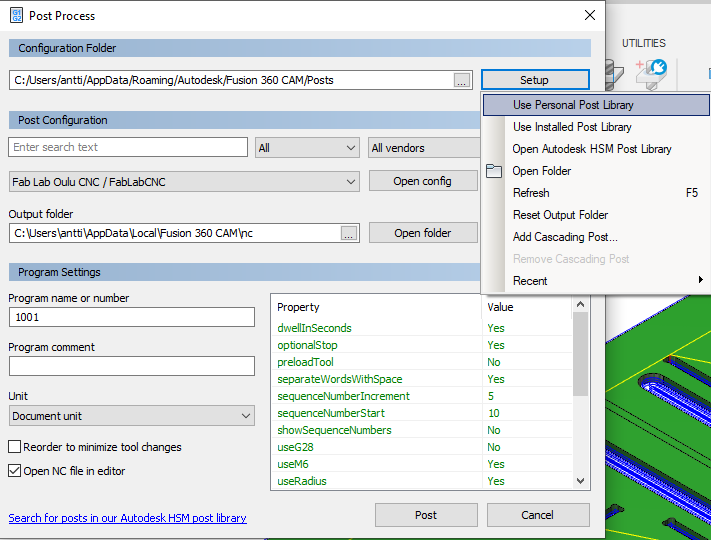 Once I can see Fab Lab Oulu CNC / FabLabCNC as machine, I’m ready to press Post and enter name for nc-file.
Third time is the charm, right? Please..?
I was told that pieces need to be separated from stock, not from each other. So stock must be left in between pieces. Well, in my design they did not.
Back to Manufacture-workspace, edit Manufacturing Model, Arrange, increase separation to 25 mm, finish edit.
 I checked the stock point, somehow x- and y-axes were wrong, so I set them again. Now toolpaths were out-of-date, but luckily I didn’t have to do all over again. I just opened each toolpath, it updated to point at new arrangement, checked all settings and hit OK. This way the toolpaths got up-to-date again!
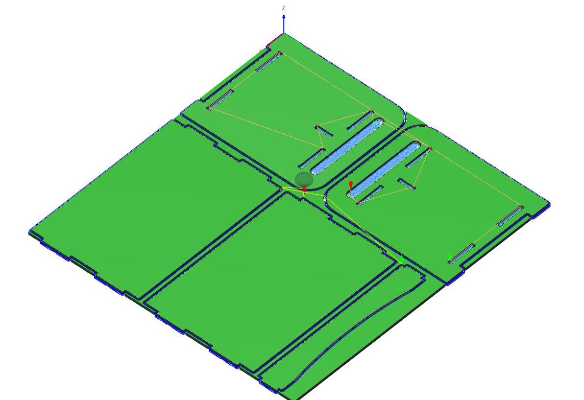 I simulated the toolpaths like before, generated G-code and exported .f3d file local PC.
To be continued :D