12. Molding and Casting
This week I will learn so much new about molding and casting, as I don’t have any previous experience on topic.
Group work
This week’s group work consisted of trying out different materials for molding. Me, Mona and Ken worked together with Ari guiding us. This week’s group work can be found at Mona’s site.
Individual work
This week I have to machine a mold for casting something. Because I have little to no previous knowledge on topic, I try to keep it simple. My individual work is supervised and instructed by Gleb Bulygin.
I would be wise to make something for my final project, such as buttons, but because it hasn’t progressed that well, I thought I’ll try to make custom keycaps for computer keyboard, such as ESC-key out of clear epoxy with a drop or two of unmixed color ingredient. But while doing group work it hit me, while I don’t have anything to work towards my final project this week, it might still be fun to cast ice or chocolate onto a shape of a Poké Ball or team Instinct logo.
Research
Existing 3D models or guides to help me progress faster:
- YouTube search: pokeball fusion360
- Readymade model of button with logo
- Phone case that has 3-dimensional logo
I also need to have rough estimate of dimensions and weight. For ice casting I think 25 mm diameter would be good for sphere shape, while button shape might work even with 30-35 mm diameter. For chocolate, each ball or button should weigh about 5-15 grams. Milk chocolate has a density of about 1300 kg/m3 or 1.3 g/cm3. So 5-15 g would be 3.8-11.5 cm3, which as a sphere shape would mean a diameter of 19.4-28.0 mm. As a 6 mm thick button the diameter would be 28.6 mm for 5 g weight and 49.5 mm for 15 g weight.
I will start working on sphere shape first. For it to be usable both as ice mold and chocolate mold, I select 25 mm diameter which as a sphere would weigh 10.6 grams.
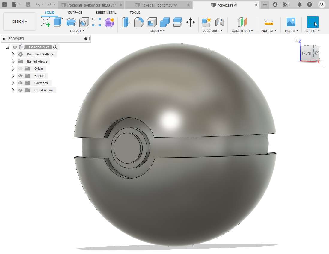
Model design
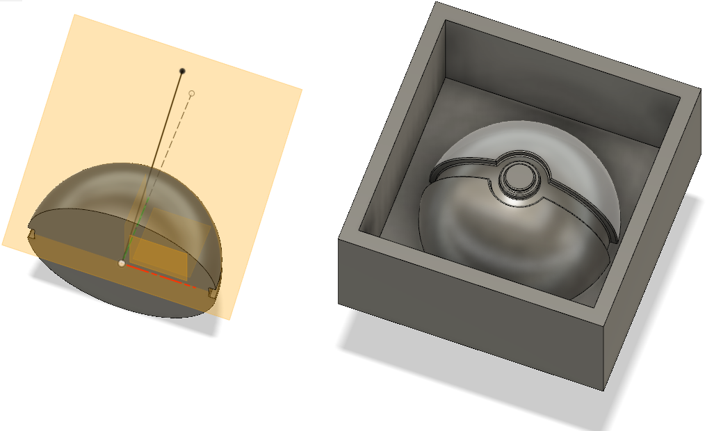
First I made just a round pokeball by making a sketch that has a circle that I cut in half. I also added indentation for the middle part of the ball and the end result of the sketch looked like a side profile of half a pokeball. Then I used revolve tool to turn it into a ball. By using an offset plane I added the button area.
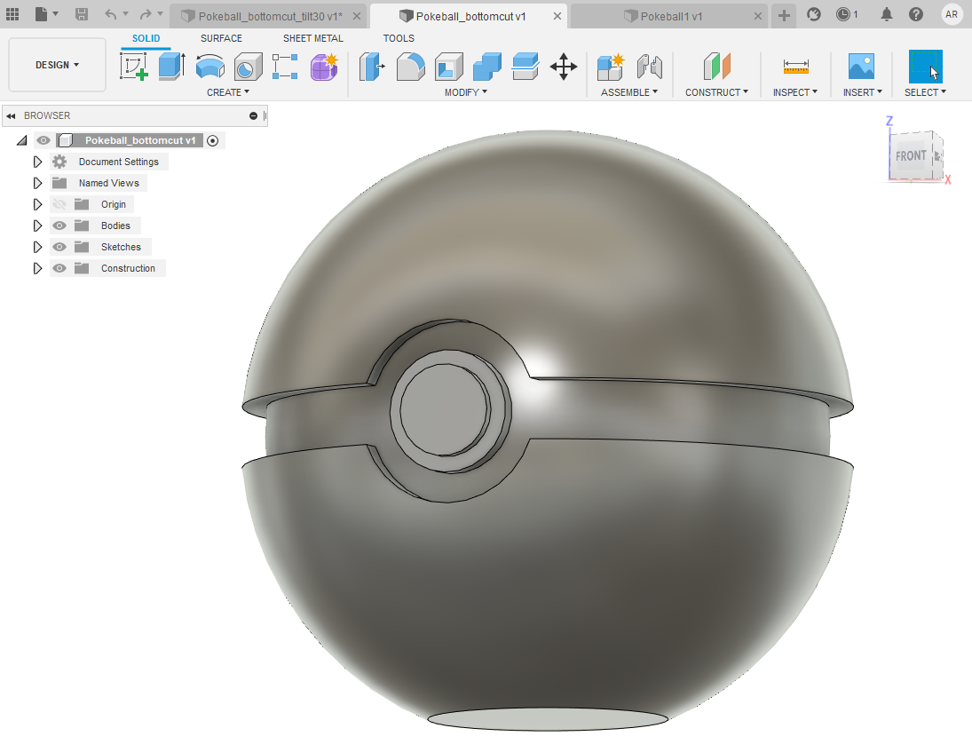
I also made two more versions: one with an offset plane on the bottom of the ball to cut small portion of bottom out so that ball can stand still.
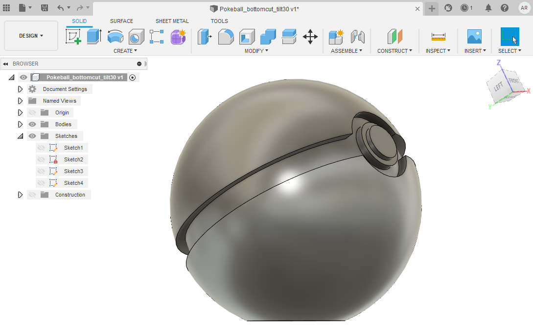
Another version had the offset plane at an angle so that ball faces upwards.
To split the ball in half I used Split body tool under Modify ribbon and selected to split in XZ-plane. Because my origin was in the center of the ball, I could use the XZ-plane connected to origin rather than having a need to set a new plane for splitting.
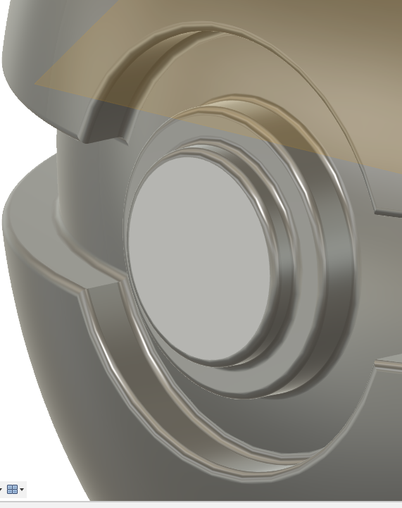
I also added chamfer to have the cast easier to remove from mould.
Preparing design for molding
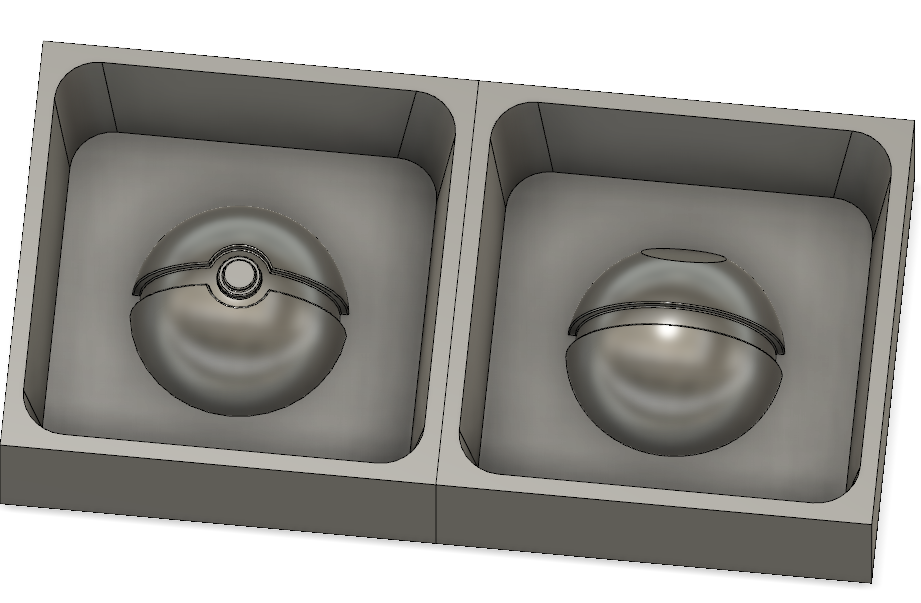
With Gleb we added a box (under Create ribbon) to my design, set dimensions as 35x35x18 mm, made a shell out of it with 2 mm wall thickness and then aligned the front half of the pokeball to the box.
Other half got the same treatment to a box that was cloned wall-to-wall next to the first box. Later box dimensions were changed to 50x50x19 mm. Larger box due to pouring shaft, deeper box to accommodate 2 mm alignment feature.
Draft tool was used on the inner walls of both boxes so that the mold is easier to remove. Walls were tilted by 7 degrees.
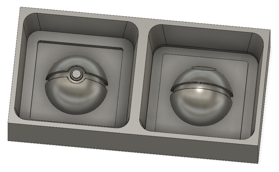
On a new sketch we added a feature to align the halves. On one sketch the alignment feature was joined and extruded upwards by 2 mm, on other one it was cut and extruded downwards by 2 mm. I was a bit surprised to be told to leave no tolerances here, but apparently Smooth-Sil 940 will cast so nicely that it doesn’t need tolerances.
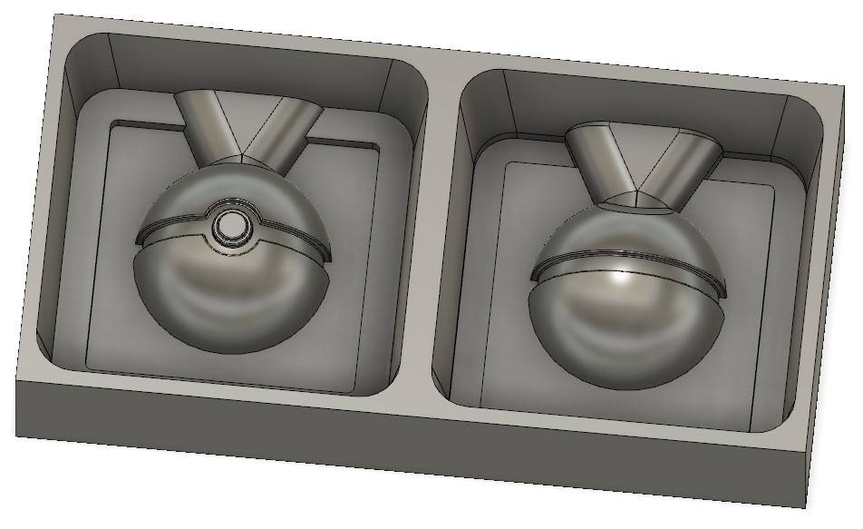
For pouring shaft a new sketch was made with lines to be extruded upwards and to be filleted. Due to drafted wall those shafts became disconnected from walls and had to be extruded to wall.
Left box before extruding shaft to wall, right one extruded.
Creating mesh and saving .stl file
On Tools ribbon, under Make button I click downward arrow and select 3D print. Then just click the body to create mesh from. After clicking I also changed refinement from medium to high.
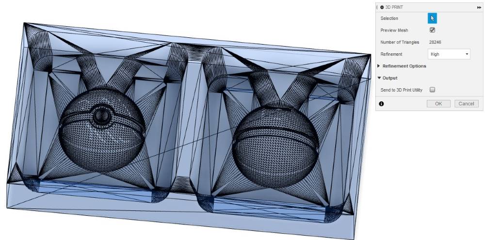
Clicking OK proceeds to saving .stl file. Pokeball_bottomcut_tilt30.stl
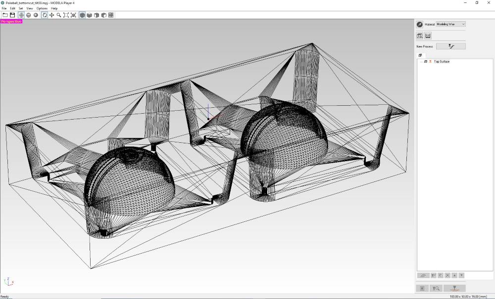
Creating roughing and finishing toolpaths for Roland SRM-20 with Modela Player 4
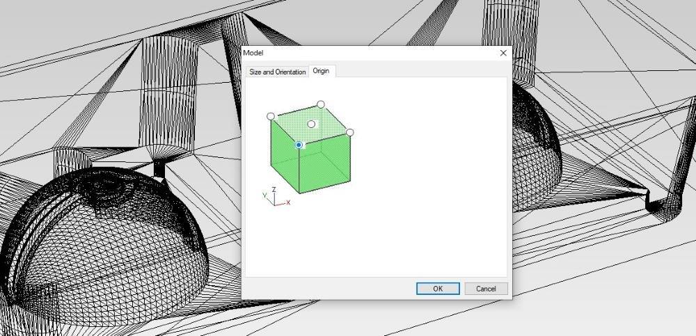
First, I loaded .stl file to Modela and changed origin from center to bottom-left corner from Options - Model - Origin(tab)
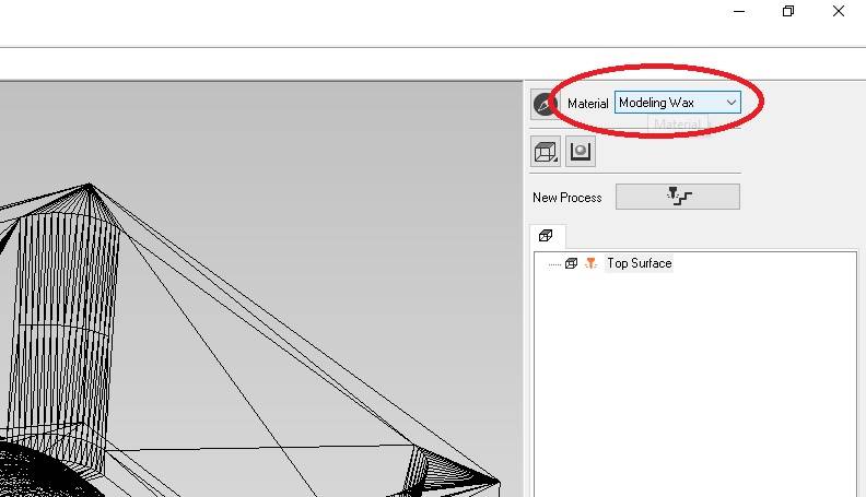
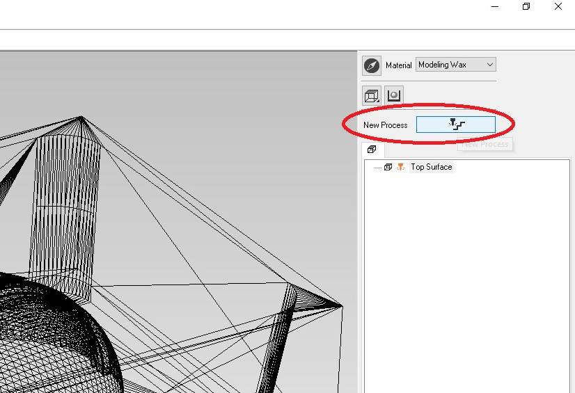
Be sure to select Modeling wax as material before proceeding!
Creating roughing process
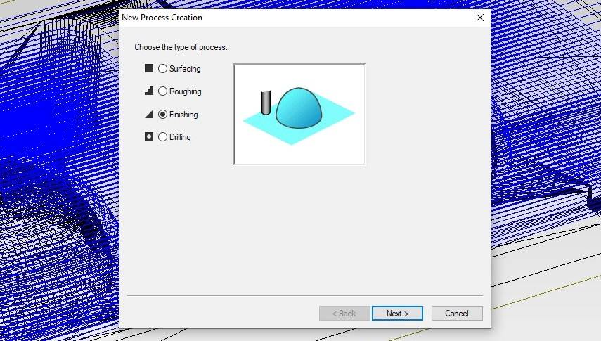
Creating a toolpath for roughing is started by clicking New process button.
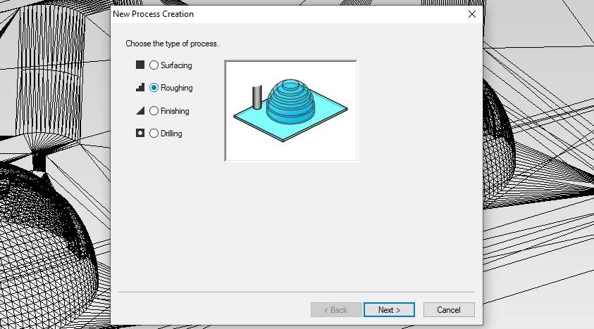
Select the process type, this time I selected Roughing.
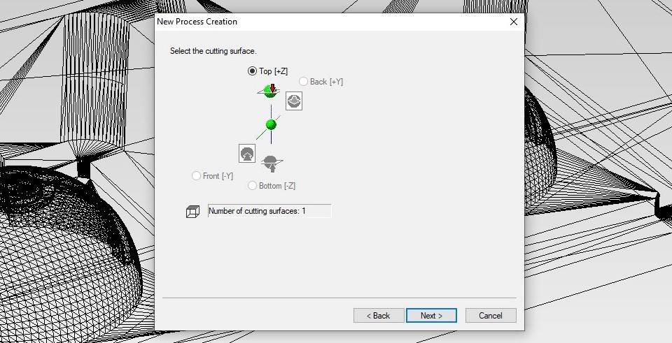
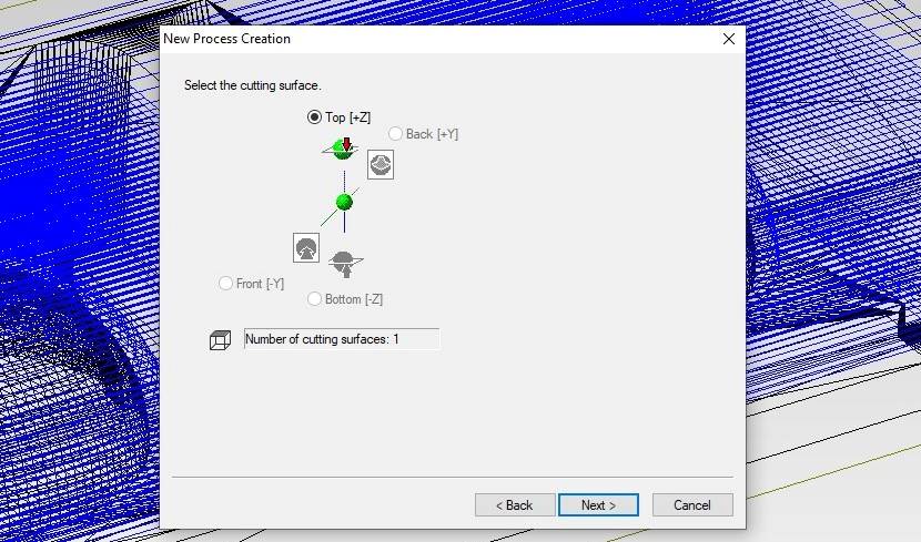
Selecting cutting surface means which way I want to to mill. If my design were oriented differently, I’d select some else direction.
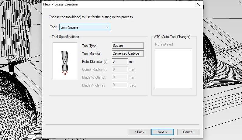
Selecting tool. For roughing I was guided to use 3 mm flat end milling bit.
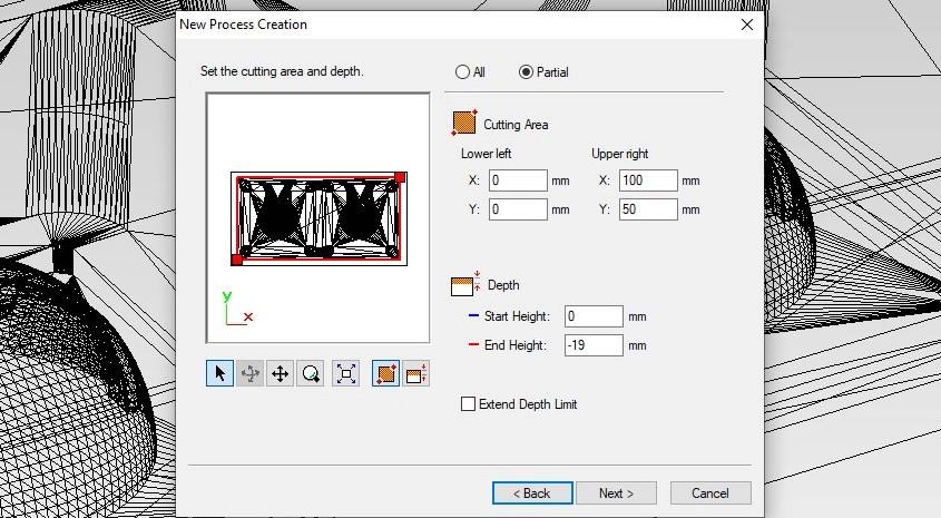
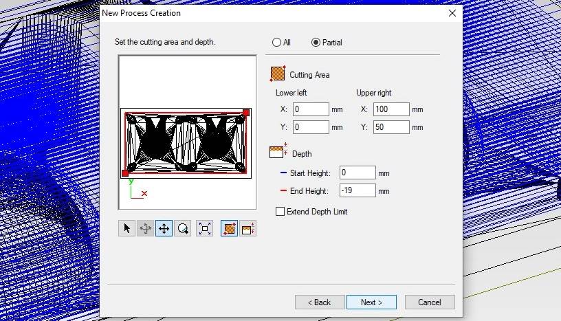
Selecting cutting area. By default All is selected, but to speed things up I can select smaller area.
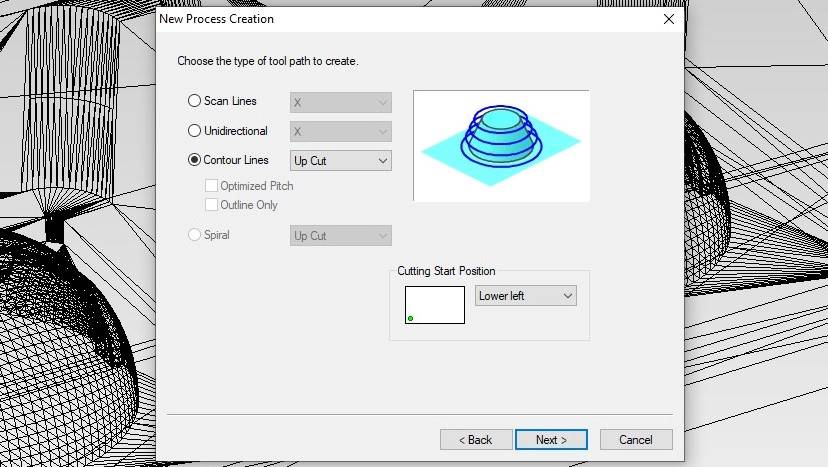
Roughing path type. Contour lines and Up cut were selected by default and I kept those. Don’t know about other options.
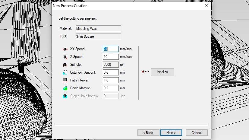
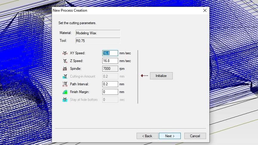
For tool parameters I checked that right tool and material were selected and clicked Initialize to have parameters loaded.
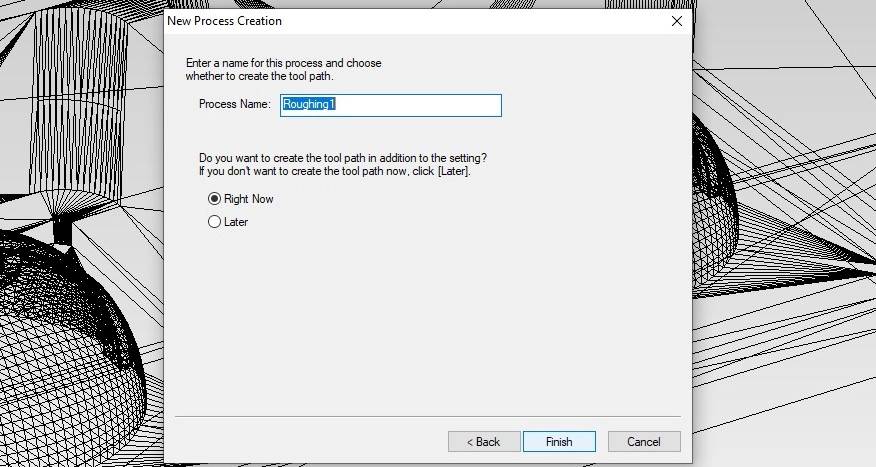
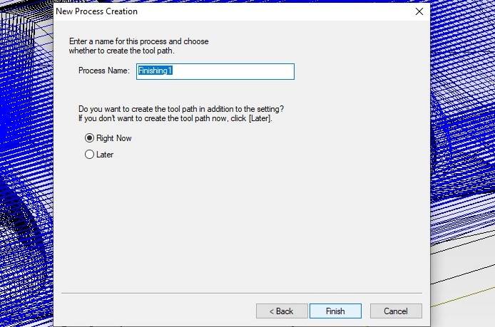
Now there’s only naming left, then roughing process is ready. I kept the default selection of creating toolpath Right now. Processes will be saved to files later.
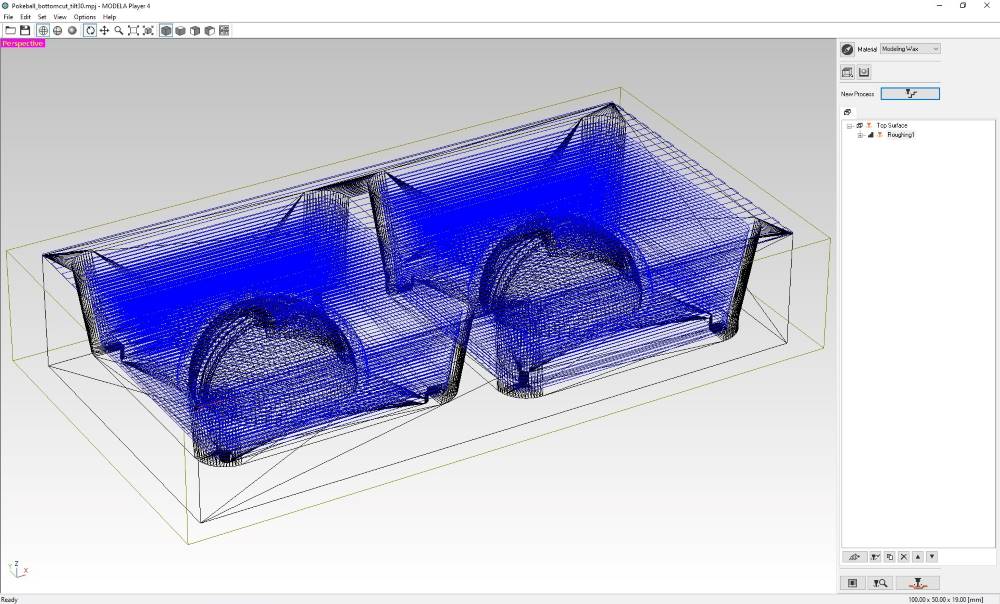
Once roughing process creation is ready and toolpath created, it will show up on default view when appropriate process is selected.
Creating finishing process
Following really similar steps to Roughing process, creating toolpath for finishing process started with New process button and selecting Finishing as process type.
I kept the same milling direction that was used for roughing.
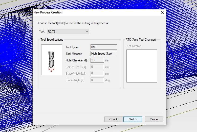
For tool, I first went with 1.5 mm ball nose tool, but the middle line of pokeball didn’t look good on toolpath simulation (6 pictures later), so I redid finishing with 3 mm square end tool (not in picture!)
For area, I selected Partial option and zeroed out the 4 mm overhead on each side, like I did with roughing.
For toolpath type Scan Lines was preselected and I selected X+Y directions for smoother result. Forgot to take screenshot of that selection.
Like with roughing process creation, for tool parameters I loaded default values for selected tool by clicking Initialize.
Only naming is left. I could give a more specific name for created process, but I kept the default name.
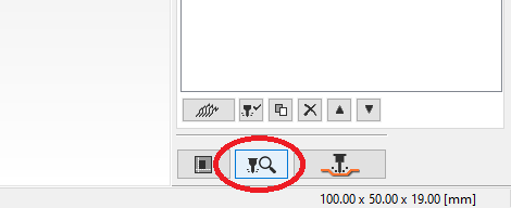
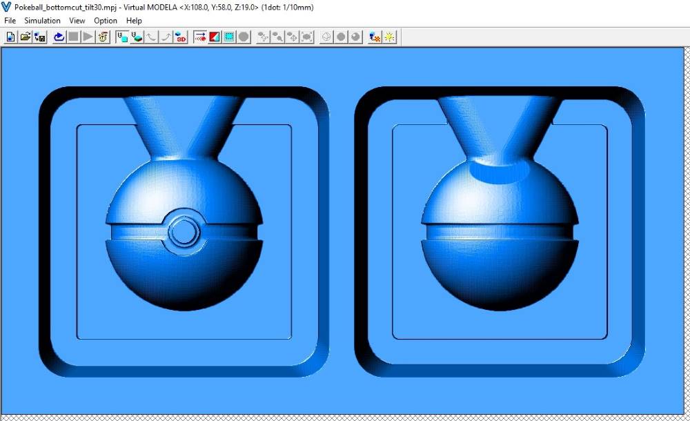
Once process(es) are ready, I can simulate them by clicking Simulation button on the lower-right corner of window.
Simulation result of my roughing process.
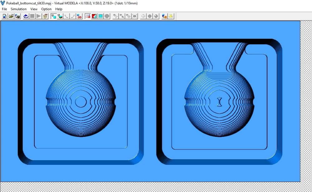
Simulation result of my finishing process.
Saving the files is done by clicking the Output button on the right to Simulation button. On save dialog there’s a checkbox whether to send processes to milling machine or create files. I created files.
Milling positive mold to wax
For milling I needed a milling machine to use, so I copied my process and project files that Modela software created, to usb stick and moved those to another computer next to unoccupied DGShape SRM-20 milling machine.
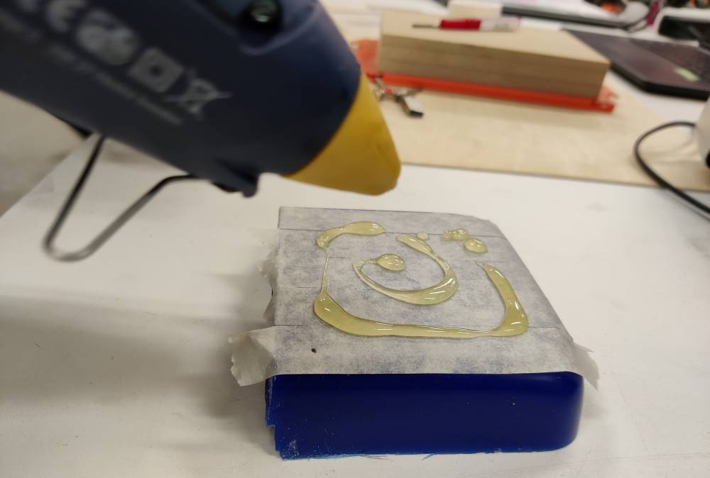
Attaching wax to milling bed
Attachment of the wax to milling bed was both sooo sketchy and so brilliant at the same time. I covered both the bed and the wax with masking tape and hot-glued wax to bed.
Milling starts
With correct milling bit set, I opened VPanel software to control milling machine. I set XY-origin to lower-left corner of the stock, but left wide margins so that machine won’t mill through the mold as my stock has slight curvature on most sides. Z-origin was set to the surface of the stock.
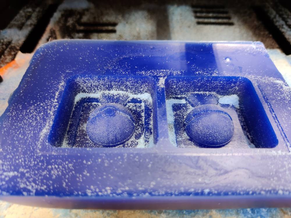
After both processes were run, I cleaned most of the wax to see result.
Don’t vacuum the milling waste, it is reusable by casting it to block shape.
Weird behaviour on DGShape SRM-20
Finishing process took 4.5 hours because milling machine kept lifting tool up every time there was nothing to mill on the bottom of design. 24 seconds was spent on unnecessary up-down movements of 36 second total it took to do one scan line in X-direction. I was using the only DGSHAPE-branded machine instead of two Roland-branded machines. While waiting for finishing to finish, I also tested the same milling file on another Roland-branded SRM-20. It didn’t do that unnecessary lifting of tool! So the reason isn’t the file itself, but on milling machine or on the computer controlling it. All three computers that have Roland/DGShape SRM-20 connected to them have the same driver for milling machine and use same version of VPanel, so the problem is likely realted to milling machine, possibly to it’s firmware.
HUGE thanks to Gleb for keeping FabLab open for such late hours!
Another finishing toolpath
While I was away for few hours, Gleb had prepared a new finishing process for me that uses 1.5 mm ball nose to smooth out that ball shape. I changed the milling bit and calibrated Z-origin mostly on the same position as I did with square end milling bit.
Hugely important thing is NOT to change XY-origin or move/remove wax stock when changing milling bit!
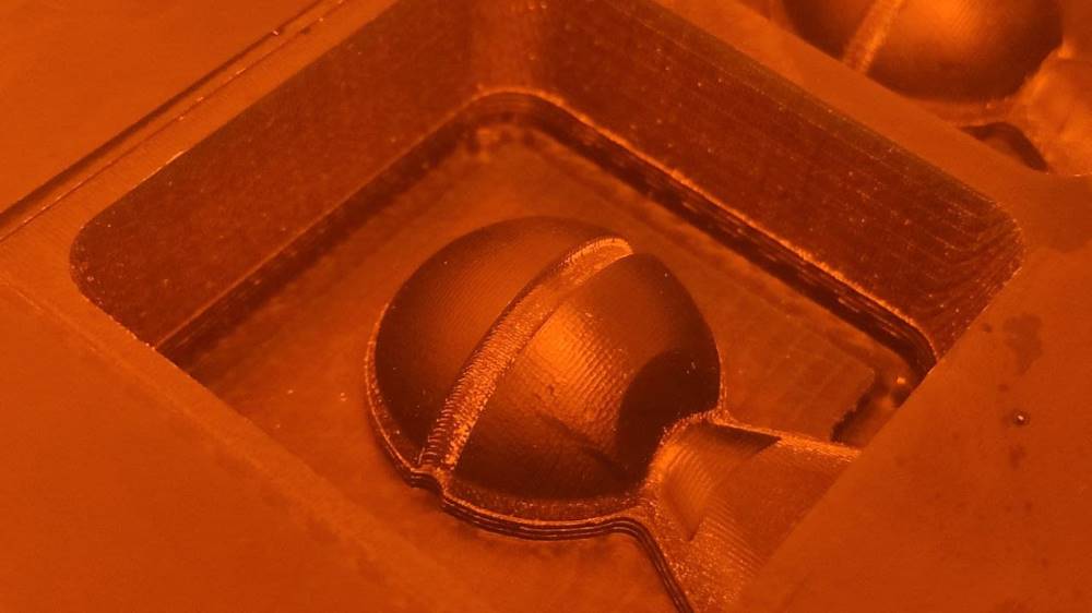
New finishing process was split into two processes, left mold and right mold. Right mold was run first and it turned out visibly smoother than with square end milling bit.
Also left mold was rerun with new finishing process and 1.5 mm ball nose milling bit.
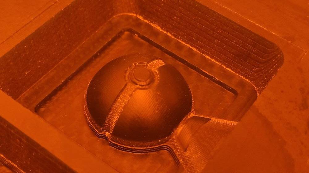
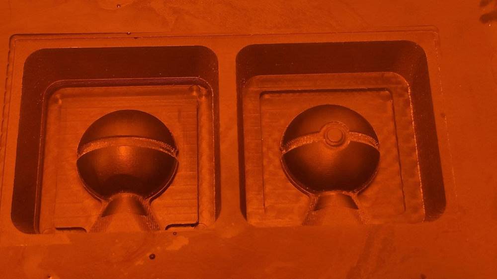
Both molds finish redone with 1.5 mm ball nose milling bit. (Pictures taken in a room that has no blue spectrum in lights due to chemical pcb manufacturing process)
Finishing the wax mold
After me and Gleb were happy with result, I carefully removed milled mold from milling machine, removed masking tape from mold and milling machine, cleaned milling machine and collected as much of milling waste as easily possible. Then I cleaned the mold under running water and dried it with compressed air.
Casting Smooth-Sil 940
I prepared to handle potentially harmful materials by wearing labcoat, vinyl gloves and protective glasses and making sure that air conditioning is turned on.
Remember that Smooth-Sil 940 has mixing ratio of 100A:10B in weight.
Measuring & mixing
I measured my molds to hold 48 grams of water, so I aimed for a bit more of Part A than that, about 55 grams. Part A was quite thick, so it was difficult to pour and I had 60 grams of it in a plastic cup. I added Part B until scale showed a result of 66-67 grams.
Vacuuming & casting
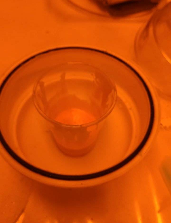
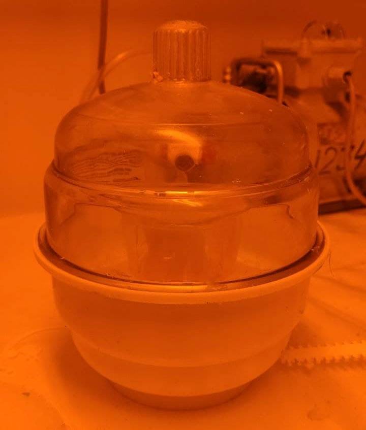
Smooth-Sil 940 needs few minutes of mixing, after which I put it to vacuum chamber to remove air bubbles.
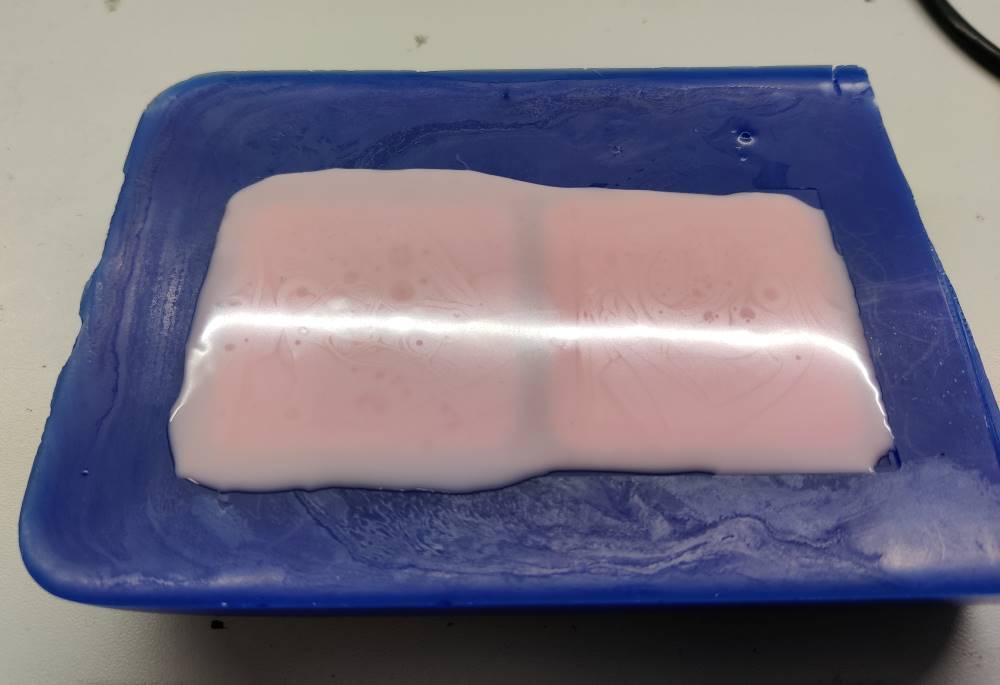
Mixed Smooth-Sil ready for vacuuming.
Vacuuming itself wasn’t that exciting. I think something was wrong with air valve this time as Smooth-Sil didn’t form that much bubbles, but Gleb told me it was fine. I later made second cast and it expanded a lot during vacuuming, so I’m quite confident that air valve was on some kind of “partially open” position on th first time.
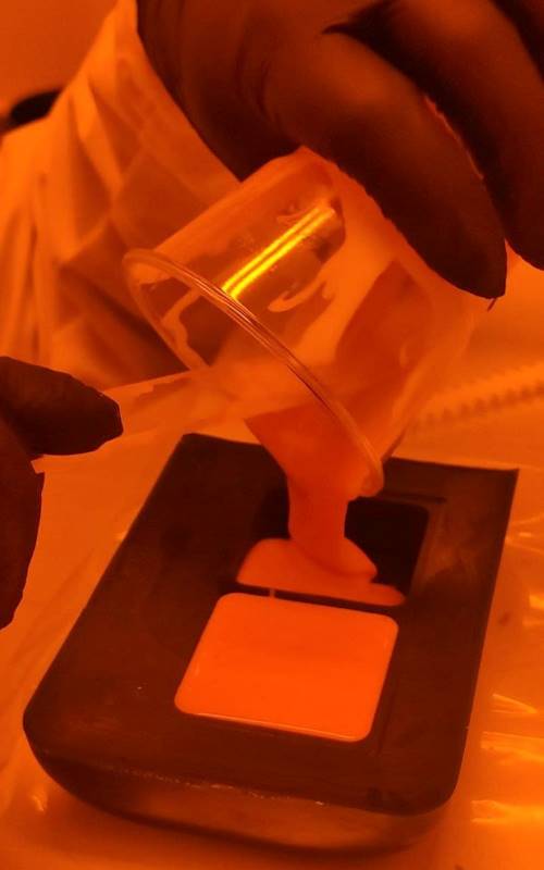
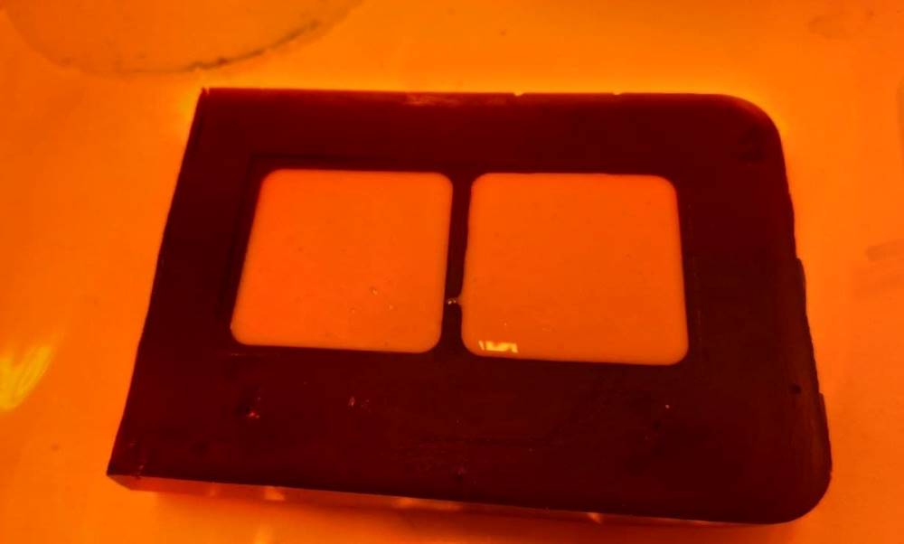
I casted Smooth-Sil from plastic cup to molds by pouring and helping the thick material to pour with a plastic stick.
Casts formed some tiny bubbles on top the cast, but I learned from Gleb that because Smooth-Sil takes 24 hours to cure, it has time for bubbles to rise up so there won’t be bubbles left on the cast surface. Those bubbles were quite difficult to get visible on camera, but this is my best shot of them.
Compared to my second cast that expanded and collapsed during vacuuming, the second cast had virtually no bubbles.
I left the cast to cure for 24 hours.
24 h later
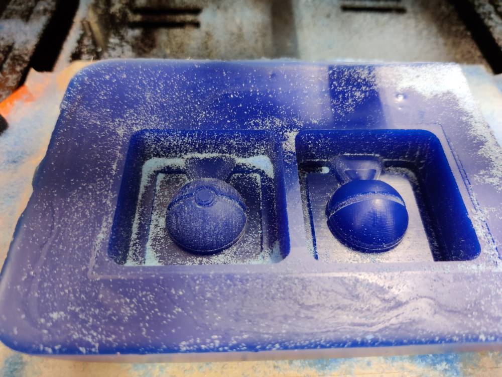
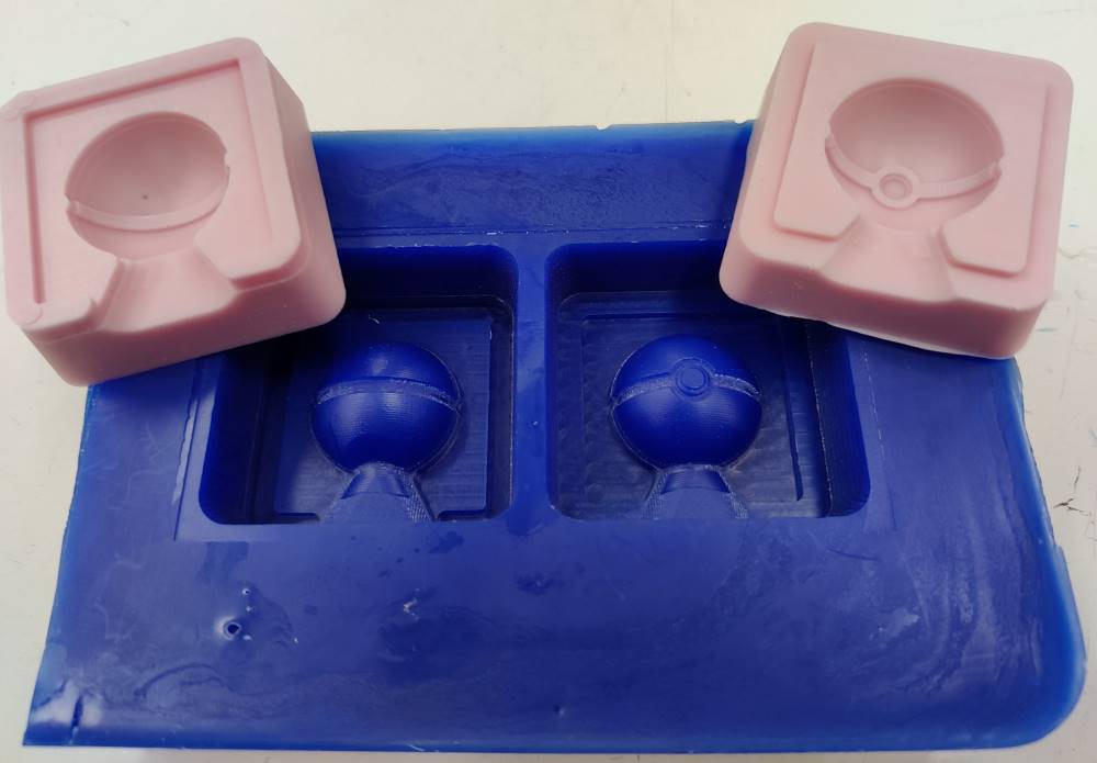
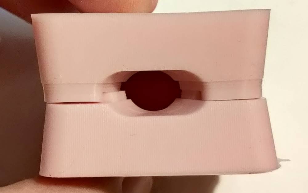
After removing silicone casts from wax mold, I can say that casts turned out really nice!
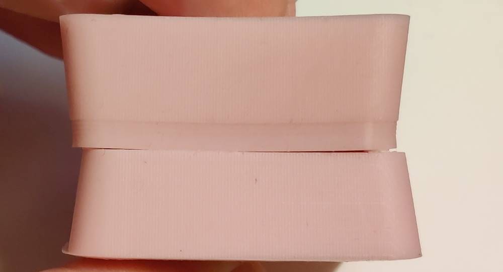
Also my second cast 24 h later turned out good.
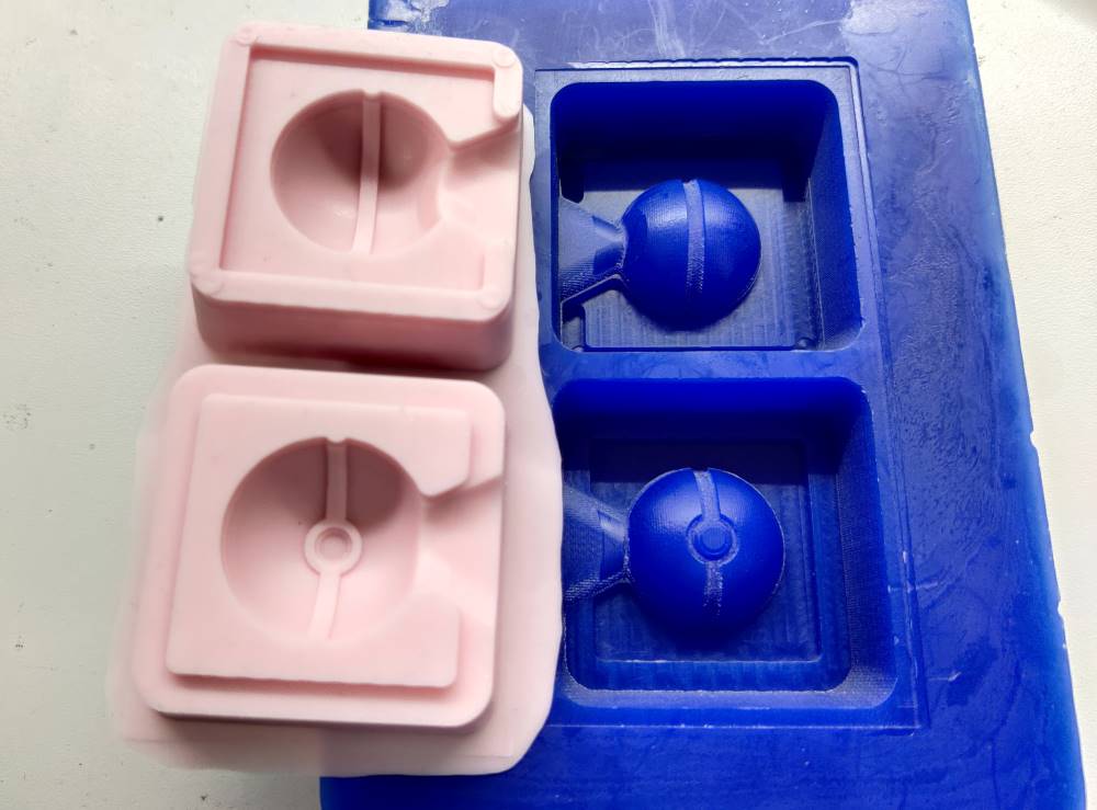
Also alignment works well. Silicone molds are quite easy to align perfectly.
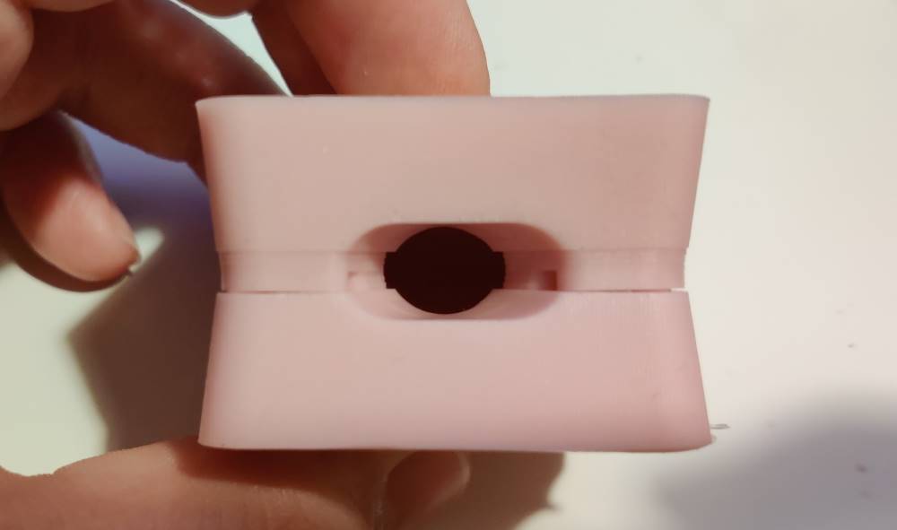
However alignment isn’t foolproof, you can misalign it if you want.
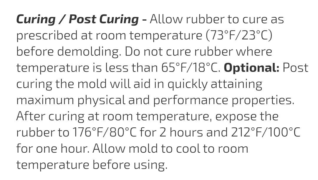
Post-processing (curing)
For post-processing I got these instructions from Gleb.
Lessons learnt
I had no previous experience on molding and casting, and I must admit I’m somewhat excited about it now! It isn’t that messy as I thought and it is easier than I thought.
Even with this quick tour in molding and casting, I leanred few things I would do differently if I would have to redo this week.
I would do finishing process differently
For rounded shape like pokeball, I’d definitely select ball nose milling bit for finishing, but I also would select square end for finishing sharp, straight edges like the groove in the middle of pokeball. So my solution would be to do two finishing processes. First for square end with areas strictly limited to where you think you need it. Second finishing process I would do with ball nose and would select whole area for it.
Roland SRM-20 vs DGShape SRM-20
Due to weird behaviour I experienced on DGShape branded machine, in FabLab Oulu I’d choose Roland-branded SRM-20 for milling wax mold. I don’t know the root cause for unnecessary up-down movements DGShape machine does, so until that issue is resolved, I’d avoid it.