8. Embedded programming
Group Assignment:
● compare the performance and development workflows for other architectures.
Individual Assignments:
● Read a microcontroller data-sheet.
● Program your board to do something, with as many different programming languages and programming environments as possible.
Gleb Bulygin , Fab Academy 2019 alumni, gave us the local lecture about Embedded programming.
1. Individual assignment
1.1 ATtiny412 data sheet
I used UPDI programmer on week 4 and the ATtiny412 board on week 6. The ATtiny412 microcontroller is using the AVR® RISC architecture, and is capable of running at up to 20MHz. It has 4KB Flash, 256bytes of SRAM and 128bytes of EEPROM in a 8- pin package.
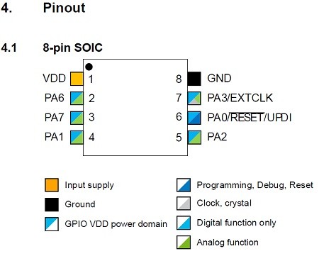
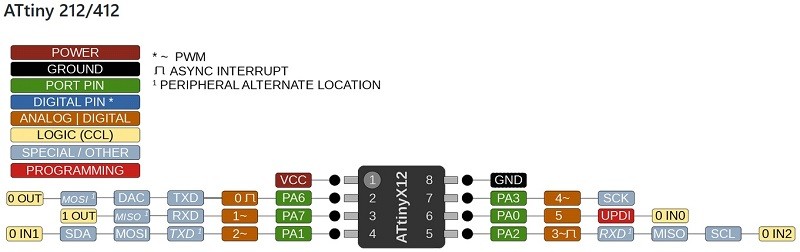
1.2 Pinout
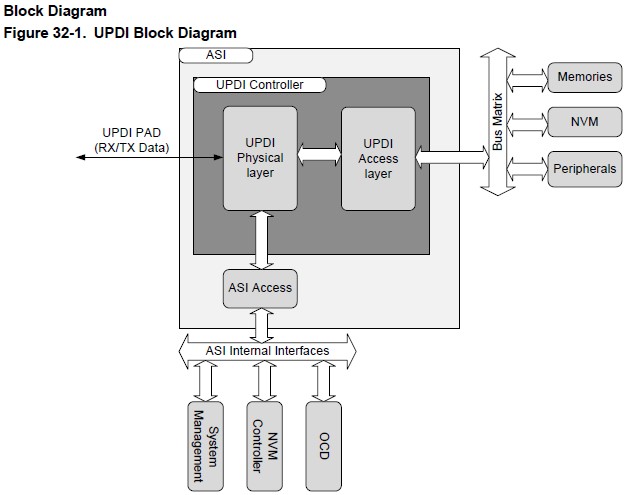
1.3 Block diagram
The ATtiny412 microcontroller system has Single Pin Unified Program Debug Interface (UPDI). UPDI is an proprietary interface for external programming and on-chip debugging of a device. Programming and debugging is done through the UPDI Physical interface (UPDI PHY), which is a 1-wire UART based half-duplex interface using the RESET pin for data reception and transmission.
1.4 Programming the board
I tested the board which made at Assignment of week6 with the code controlling LED with push button.
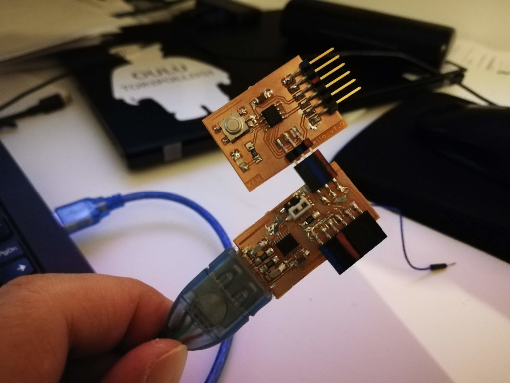
Programming to the board is the same way of previous week6, using Arduino IDE and FTDI board which is made in week4. First I tried with this simple code. From Pinout and circuit diagram of the board, I set output LED is 0, and input push button is 1.
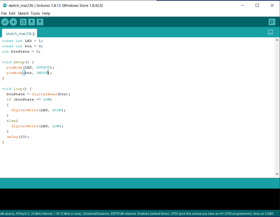
And upload to the board using COM3 (at my PC). After uploaded and run the program on the board, however the LED lamp is always on even not pushing the button…
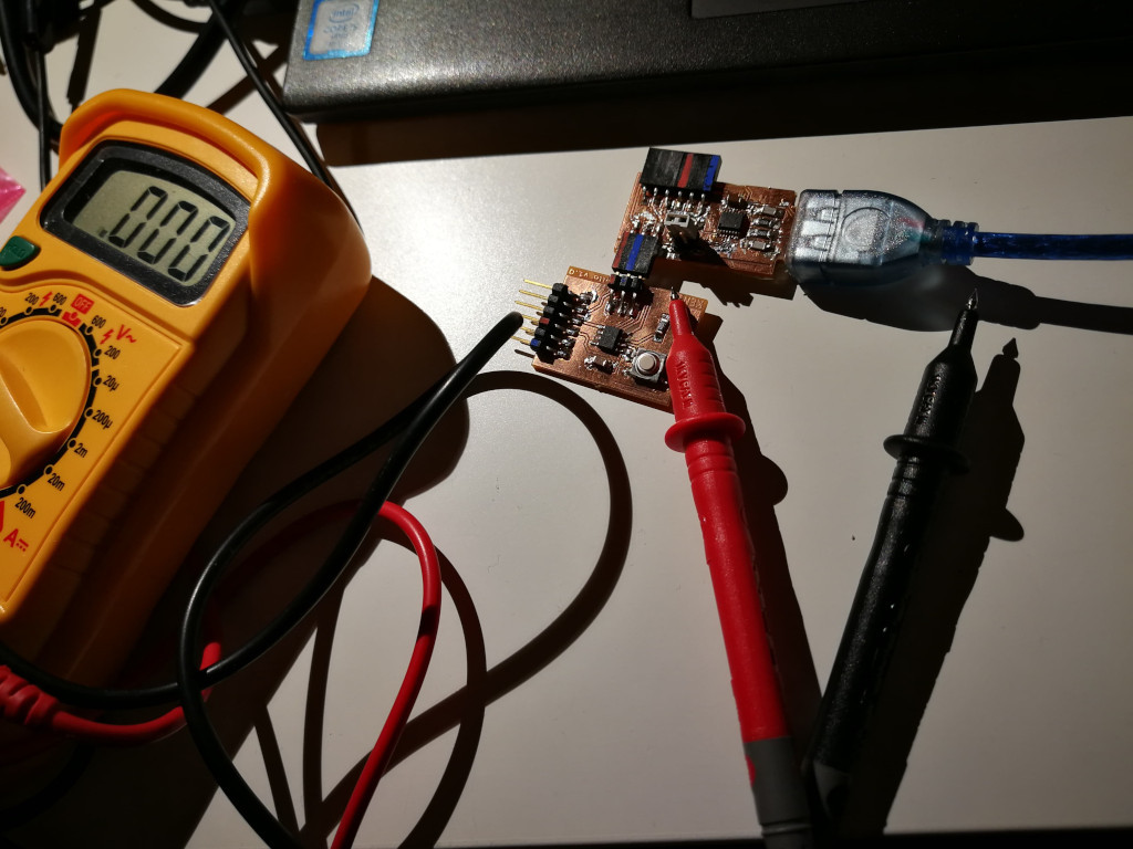
I checked the voltage on the #2 pin of input
- 1.6V
It is something wrong, not reaching to 5V and this made always LOW state even not pushing button…
This board circuit design, the input from button is not added the pull up register because of using internal pull up on the IC… This was the reason the voltage of the pin cannot be HIGH state. I checked how to make the pull up state using internal pull up, it was simple, changing the code from
pinMode(btn, INPUT);
pinMode(btn, INPUT_PULLUP);
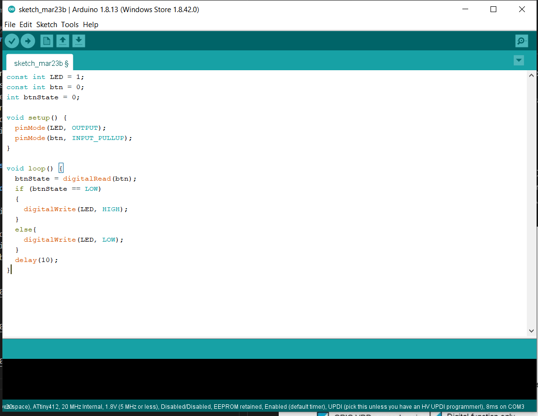
Then after uploaded the code to the board, the LED lamp can work properly with pushing the button. And I measure the voltage of the input pin, it shows 4.8V when not pushing the button.
2. Group work, compare the embedded devices
We compared the several embedded devices with the group of Antti, Mona and Helle (remote). The report can be found here Mona’s report.
reflections
It was good learning about pull up resister for digital input with simple mistake but deeper investigation. Also compare the embedded devices with group work, could understood the different performance and it was good opportunity to touch and try different devices.