Embedded Programming

Final Project

For programming in Arduino, I needed to find the proper library to use in the code. I made a quick search to find some examples on the interent and found this sample from Tinker Projects. It seems one of the most common libraries for deltabots is DeltaKinemtaics which allows to transform from Cartesian coordinates (X,y,z) to angles for the motors. I downlowded the zip folder and added it to the Arduino libraries. In this library:

DeltaKinematics(double ArmLength,double RodLength,double BassTri,double PlatformTri)

This Fuction is set up the class to calulate the forward and inverse kinematics for the delta. ArmLength, RodLength, BassTri and PlatformTri are the set values from the Delta robot defined as the following:

  • ArmLength: Lenght of the first arm (mm)
  • RodLength:Lenght of the second arm (mm)
  • BassTri: Distance (Sb) of the upper platform (mm)
  • PlatformTri:Distance (Sp) between the axle and the lower paltform (mm)

See image below to see how to take the measurement.

Millimetre, meters, inches or any other lenth measurement can be used for ArmLength, RodLength, BassTri and PlatformTri. The measurement will need to be the same for x, y and z.

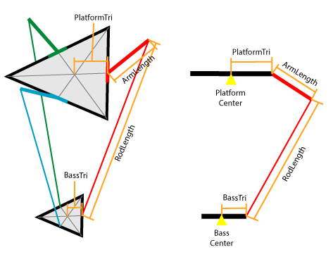
For my delta robot this line would be as (in mm):

DeltaKinematics DK(63,125,030,85);

Another library would be AccelStepper which provides an object-oriented interface for 2, 3 or 4 pin stepper motors and motor drivers.

I started with the code using in this project and modify it based on my own data. (stepPin and dirPin assigned to each driver and also the free pins in the board).

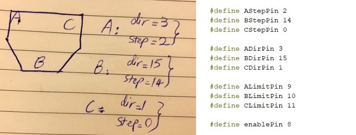
As I explained in Electroncis design and production, I had three limit switches on the upper plate connected to the main board that could be touched by the upper arm and helped me to find the origo. I used the free pins on the microcontorller by:

#define ALimitPin 9

#define BLimitPin 10

#define CLimitPin 11

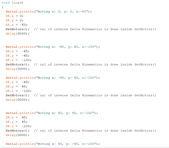
After several tries, finally, I set the home positioning by measuring the approximate angle of arms.

Then, I needed to figure out guiding the steps. First, I started with z positioning and then, added the movements in x and y directions. I started with the z movement (here, upper moves are assigned with minus values according to the aligmnemt of the axis) and then, added moves to x and y.

Then, to have an interface with the machine, I tried to modify the current code with adding serialEvent but the machine was not working with that. Aftet a quick search and with the great help of Ivan, I found that it would not work with my microcontoller (ATtiny3216) (See here). So, I changed the code to Serial.available() as the following.

  • readStringUntil() reads characters from the serial buffer into a String.
  • indexOf() locates a character or String within another String. By default, searches from the beginning of the String, but can also start from a given index, allowing for the locating of all instances of the character or String.
  • substring() Get a substring of a String. The starting index is inclusive (the corresponding character is included in the substring), but the optional ending index is exclusive (the corresponding character is not included in the substring). If the ending index is omitted, the substring continues to the end of the String.
  • toInt() Converts a valid String to an integer. The input String should start with an integer number. If the String contains non-integer numbers, the function will stop performing the conversion.

Then, according the the previous test, I set a starting point as:

Serial.println("Moving x: 0, y: 0, z:-60");

DK.x = 0;

DK.y = 0;

DK.z = -60;

And complied the new code. Then, I connected the board and computer with a FTDI cable and put different set of values as x:y:z in serial monitor to control the deltabot.

The full code I used for serial communication was as the following: