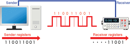
is a communication method that uses one or two transmission lines to send and receive data, and that data is continuously sent and received
at a time. Since it allows for connections with few signal wires, one of its merits is its ability to hold down on wiring material and relaying equipment costs.
.
An asynchronous serial interface operates without an external clock signal. Its operation is controlled by these four parameters:
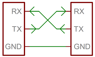
consists of just two wires - one for sending data and another for receiving. As such, serial devices should have two serial pins: the receiver,
.
The key idea in a simple serial bus between microcontroller is that when the node sends a response, the Tx pin is switched to output state and back to input after sending. The default state is input to not interfere with other nodes.
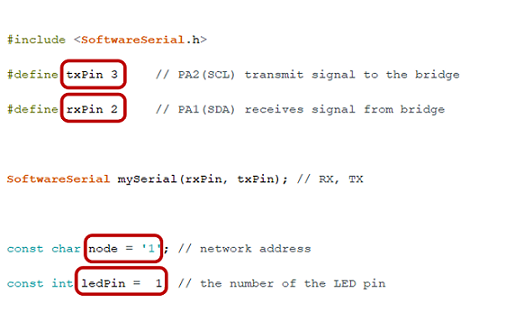
I started to assign different nodes to the two blinking boards with different microcontrollers I made during Week 6: Electronics Design and Week 10: Input Devices . First, I started to program the board with ATtiny412 which was connected to LED with pin 1 (PA7) while pin 2 (PA1) and pin 3 (PA2) were connected to RX and TX , respectively.
The full arduino code for serial bus (with ATtiny412 board)
Here, I noticed the 1x3 male connector had been detached from the board and I was afraid to have to make a new board. But Juha-Pekka, our week instructor saved me and fixed the issue with the glue and resoldering.
Figure 4. Fixing the detached connector with glue
Then, I started to connect the programmer to PC with the USB cable and also, to the board with ATtiny412.
Figure 5. programmer and board connections
Next, I uploaded the code and programmed the board as Node 1 and blinking.
Figure 6. Uploading the code in Arduino
Then, I attached the cables to FTDI of the both boards.
Figure 7. Connecting FTDI cable to the programmer
To test the programmed board, I went to Tools->Serial Monitor and entered 1 to see if it is blinking and then, entered other numbers to see what is the difference in output. I noticed although it was working well with blinking, it had issues in output printing and there were some trash bites as in the Figure 8. Then, with the suggestion of Juha-Pekka, I changed the setting from Newline to New line ending and it worked! Also, remember to check the Baud rate as 9600 as it is defined in the code.
Figure 8. Setting changes in serial monitor to fix the output
The following video shows testing the board first by pressing 1 (two blinking) and then, 2 (one blinking).
Testing the ATtiny412 board
Testing the ATtiny1614 board
For programming this board, I needed to modify the previous code as the following according to the ATtiny412 pinout and my schematic design:
txPin 5 (PB2(RXD))
rxPin 4 (PB3(TXD)
node = '2'
ledPin = 10
Figure 8. Programming ATtiny1614 board in Arduino
Similar to the previous board, first, connect the board to the programmer and then, connected it to FTDI to test the program.
Figure 9. connecting ATtiny1614 board to the programmer
After successfully uploading the code, I tried to test with through the serial monitor as previous with this difference that this time, I expected to see two times blinking with 2 while only one blinking with 1 which as it is shown in the following video, it worked well!
Testing the ATtiny1614 board
HM-10 Bluetooth Module
Then, Juha-Pekka suggested me to try Bluetooth connection with using a Bluetooth module which will transfer data through the TX pin to the RX pin of the Arduino. I used HM-10 Bluetooth Module which is a 34-pin module but we only need four pins of all 34 to establish a communication.
Figure 10. HM-10 Bluetooth Module
This module is used where short distance wireless communication is needed (less than 100 meters). HM-10 MODULE is designed by Bluetooth low energy (BLE) chip so it consumes very less power to function. So the module can be used on mobile systems
I connected the module to my hello board from Week 6: Electronics Design with following circuit connections:
VCC to VCC
GND to GND
TXD to pin 5 (RX)
RXD to pin 4 (TX)
Figure 11. Circuit connection between ATtiny412 Hello board and HM-10 Bluetooth Module
Then, in Arduino I wrote this code which refers ledpin as 1 and pins 2 and 3 as switch pins (referred to TXD and RXD) for ON and OFF, respectively.
The full arduino code for connection between ATtiny412 Hello board and HM-10 Bluetooth Module
The commented lines are for Arduino UNO operation where software and hardware serial ports can be utilized. But in my case with ATtiny412 board, it is not applicable.
Figure 12. Uploading the code to the board
To connect to the HM-10 and to read the services and characteristics we need to use a BLE app. Since I am using IOS system, Juha-Pekka suggested me to install BLE Scanner app Which is applicable with iPhone devices. I used this inclusive tutorial for the connection steps.
Once the installation is completed, open the App and enable Location and Bluetooth permission. Scan for the bluetooth devices. The name of HM-10 BLE 4.0 device is CC41-A . So, choose it and conncet it to your device. As soon as the deviced are connected, the mudule will stop blinking.
Then, click on it and you will get SERVICES options including Device Information and Custom Service. Click on CUSTOM SERVICE .
Next, go to Wrtie,Read,Notify,WriteWithoutResponse .
Then, click on Write Value .
Figure 13. Reading the characteristics of the HM-10 using using BLE Scanner
Now, simply type 2 from Text referring to LED ON and you will see the light will be on.
Figure 14. Testing LED ON by sending 2
Then, type 3 referring to LED OFF and the light will be off.
Figure 15. Testing LED OFF by sending 3
Reflection
During this week, I learnt more about programming in Arduino and also, got familiar with networking and communication by using a Bluetooth module which was absolutely new for me. In addition, during struggling with connections for the circuits, I knew more about the logic behind the pins connections.