Assignments
Group assignment:
- Compare as many tool options as possible
Individual assignment :
- Write an application that interfaces a user with an input &/or output device that you made
Week 14
I was in the group with Antti and Kenichi and we divided the tools as the following in such a way that each of us had the chance to test 1-2 of them and get familiar with them:
Processing is a simple programming environment that was created to make it easier to develop visually oriented applications with an emphasis on animation and providing users with instant feedback through interaction. The developers wanted a means to “sketch” ideas in code.
First, I downloaded and installed Processing in my computer. Then created a new Processing sketch and copied the simple "hello world" skecth from the github and used Arduino Uno board.
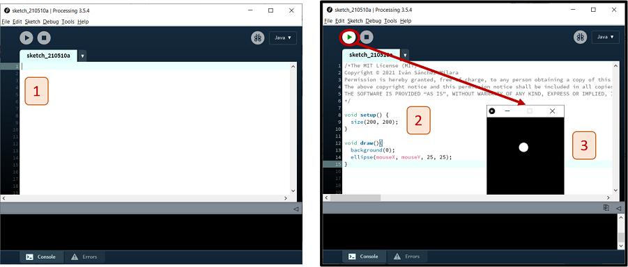
Figure 1. Uploading and running a sketch in Processing.
The Processing equivalent of a "Hello World" program is simply to draw a line:
line(15, 25, 70, 90);
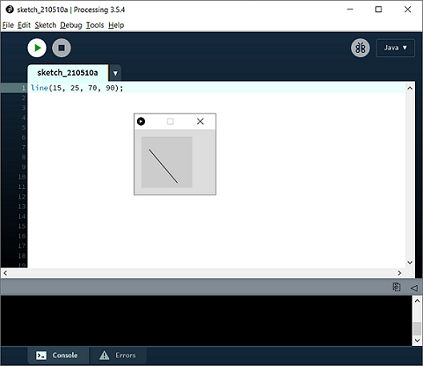
Figure 2. Drawing a line in Processing.
Then, in Yazan's page, I found an example of how to print “Hello world!” in the console (Figure 3) and how to print it on a window. Window is created with size(x,y) and the background is set as yellow throuhgh background(255, 204, 0). Besided printing command, we should also define the format of the font including its type, size and filling color (fill(0,0,0) for black) as they are marked in Figure 3 with red line. To avoid overlapping the printing texts, I had to modify height.
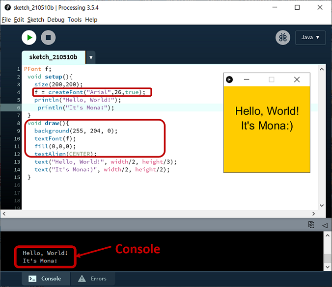
Figure 3. Uploading and running the "Hello, World!" sketch in Processing.
Blynk was designed for the Internet of Things. It can control hardware remotely, it can display sensor data, it can store data, vizualize it and do many other cool things. There are three major components in the platform:
Every time you press a Button in the Blynk app, the message travels to space the Blynk Cloud, where it magically finds its way to your hardware. It works the same in the opposite direction and everything happens in a blynk of an eye.
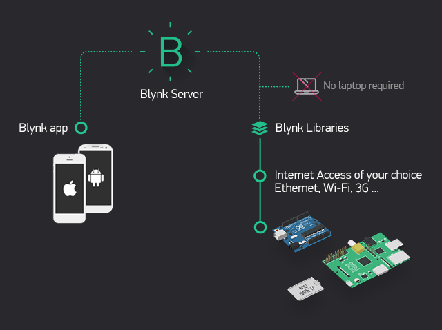
Figure 4. How Blynk Works [ref.]
First, I installed IOS version to my phone, then opened the App and created a new account. An authentication toke will be sent to your email for each one of the projects you create in Blynk. Then, I installed Blynk Library in Arduino IDE through Sketch->Include Library->Manage Libraries.... Then the Library Manager will open and you will find a list of libraries that are already installed or ready for installation. Search for Blynk library and in the version selection choose the latest version to date. Then, I installed the ESP8266 development board in Arduino IDE. I followed the next steps from here:
Then, I created a new Blynk project in my phone, selected the right board and chose a name for the project
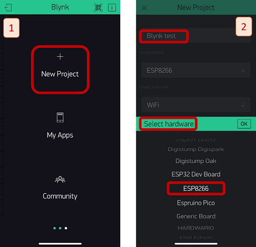
Figure 5. Creating and setting a new project in Blynk
In Arduino IDE, choose the right board as Figure 6.
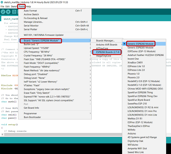
Figure 6. Choosing the right board in Arduino IDE
I used the following code in Arduino:
MIT App Inventor is an online platform designed to teach computational thinking concepts through development of mobile applications. Students create applications by dragging and dropping components into a design view and using a visual blocks language to program application behavior. The MIT App Inventor user interface includes two main editors: the design editor and the blocks editor. The design editor, or designer, is a drag and drop interface to lay out the elements of the application’s user interface (UI). The blocks editor is an environment in which app inventors can visually lay out the logic of their apps using color-coded blocks that snap together like puzzle pieces to describe the program.
Kenichi had already worked with MIT App Inventor during Networking and Communications week and you can find inclusive instructions on his page.
First open the programming webpage of App Inventor. After defining the name of project, the designer view is shown with smartphone view. Then, add a simple Text Button and change the view of blocks. This is similar operation as Scratch coding blocks.


Figure 8. Adding blocks in MIT App Inventor
When setup is done on PC, you can connect with phone and the phone can run this code and verify the functions.
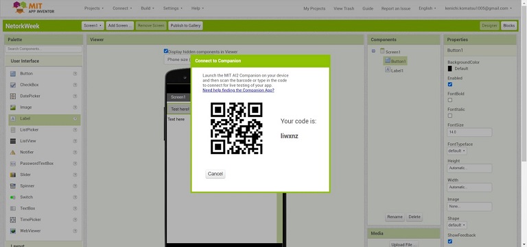
Figure 9. Connecting pc to the phone in MIT App Inventor
For this test, ESP32 board which is made in Kenichi's previous week and upload the code there.
ESP32 coding, he used the default library of ESP32 regarding Bluetooth connectivity. And set the LED function using digitalWrite for GPIO #23 when received the Bluetooth serial “1” or “0”. Also set up the debug purpose serial print and can confirm the signal of Bluetooth connection.
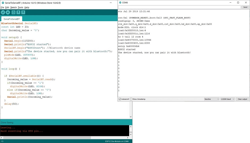
Figure 10. Configuring in Arduino IDE
To transfer the code from the website directly to your mobile phone, you need to install MIT AI2 Companion App.
For working with Adafruit IO, first of all you need to create an acount to sign up. Then, go to Dashboards -> New Dashboard and create new Block (e.g. a Toggle Button). This time, the developement kit of ESP8266, (NodeMCU v2 - LUA ) is used for test.
In Arduino IDE, install “Adafruit IO Arduino” by Library manager (ESP8266).
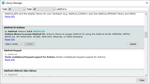
Figure 11. Adding Adafruit IO Arduino library in Arduino IDE
To check the connection with ESP8266 and Adafruit IO webpage, try the example of “adafruitio_00_publish”
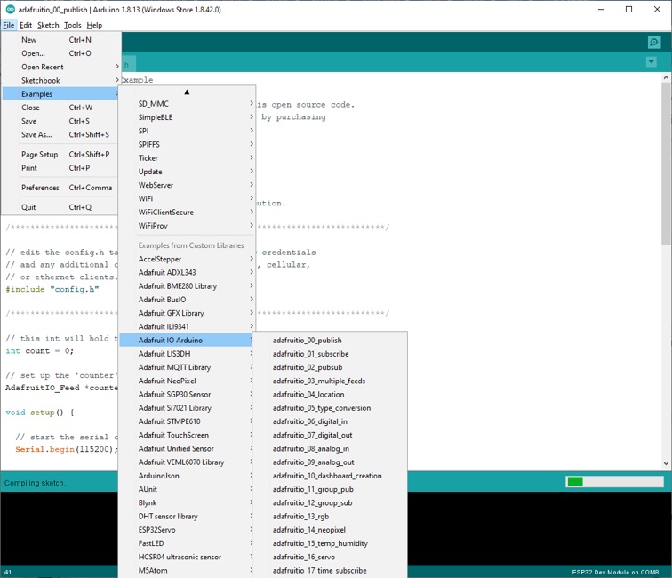
Figure 12. Testing the example “adafruitio_00_publish” from the selected library
Then, change the account info of Adafruit IO and Wifi SSID and Password of your local Wifi connection.

Figure 13. Adding the account info according to the username and Active key
Next, upload the file to ESP8266 and reset the board, then for Wifi connection, the ESP8266 connects to internet and Adafruit IO web site. Profile -> Monitor can show the live data of connections.
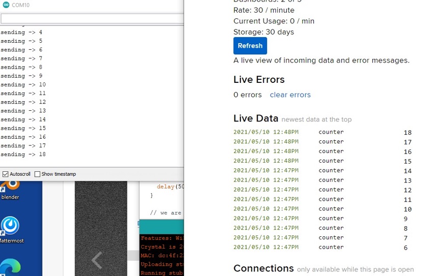
Figure 14. Wifi connection and live data in Adafruit IO
MQTT, or message queue telemetry transport, is a protocol for device communication that Adafruit IO supports. Using a MQTT library or client you can publish and subscribe to a feed to send and receive feed data.
Feeds are the core of the Adafruit IO system. The feed holds metadata about the data you push to Adafruit IO. This includes settings for whether the data is public or private, what license the stored sensor data falls under, and a general description of the data. The feed also contains the sensor data values that get pushed to Adafruit IO from your device. You will need to create one feed for each unique source of data you send to the system. For example, if you have a project with one temperature sensor and two humidity sensors, you would need to create three feeds. One feed for the temperature sensor, and one feed for each humidity sensor.
Tkinter package (“Tk interface”) is defined as the “standard Python interface to the Tk GUI toolkit”.
First thing to get strated with tkinter is to install Python. Newest version at time of this group work was 3.9.5, which was installed. Tkinter is installed by default in Python installation.
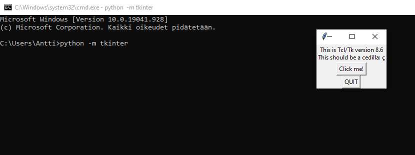
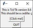
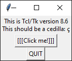
After installation, Tkinter can be tested by running python -m tkinter in command line.
Clicking button adds [ ] brackets around “Click me!” text. Screenshots after 1 and 3 clicks.
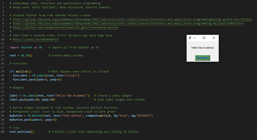
With help of Iván’s Gitlab wiki pages and GitHub repository and John Elder’s Youtube video‘s first 30 minutes, creating basic elements with Tkinter was easy.
Starting with import, Tk() and mainloop() commands, empty Tkinter window can be produced.
Adding labels (text boxes) and button is quite easy, but packing those to window must not be forgotten!
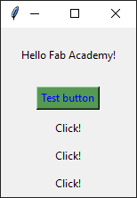
Tkinter code and window it creates:
Tkinter window after 3 clicks:
We have tested five different application developement tools, Processing, Blynk, MIT APP Inventor, Adafruit IO and Tkinter. Processing and Tkinter are more for code oriented developement tools, Blynk and MIT APP inventor are GUI orientend developement tools. GUI oriented Blynk and MIT APP inventor are work friendly, easy to understand for beginers but it is needed to registration and a bit complicated setups for PC, phone and devices. Once environment is ready, it's easier developement environement but also it costs subscription fee. Processing and Tkinter have more straightforward path for the programmers . It is easy to make hello world and functional demo use case but difficult nad time consuming to create and handling widgets such as button, images or labels.
For this week, I decided to use Processing with the board I made for Input Devices week which had ATtiny1614 microcontroller and was programmed for an ultrasonic sensor. I tested two codes with different UIs. The first one was with a car image which its sizes increased and decreased by changing the distance while for the second test, I tried a black background with a text displaying the distance and would be modified if the distance is changed. I started with the Arduino code I tested before:
I had no prior knowledge about interface tools but during this week, I briefly learned about a couple of them including Processing that I worked with it for my individual assignment and tried to generate UI for the board I made during Input Devices Week. I also got familiarized a bit how the pc is supposed to connect with the phone through an application. I also learned about different codes applied for defining UI in processing.
