For my final project, I decided to find some ideas related to my research to help my measurements. Then, after discussing with my supervisor, I came up with two ideas. I am working a spectroscopic setup using fiber optics to probe meat samples. But in that setup, there is no focusing and there are no lenses on fibers to focus light on the sample and/or to collect light from the sample. For conducting long-time measurements, focusing is more important since it could provide better signals. So, I am going to design and make a 3D scanning of the fiber probe over the sample surface, to make spectral mapping (because different parts of the sample might change differently) – this as a much cheaper alternative to camera imaging.
After a short research and several discussions with Fablab Oulu instructors, I came up to make a Delta Robot holding the fiber optic moving over the sample to scan it.
Final project requirements
Our project should incorporate these units:
- 2D and 3D design
- Additive and subtractive fabrication processes
- Electronics design and production
- Embedded microcontroller interfacing and programming
- System integration and packaging
What will it do
The base plate of the delta robot will be attched to an optical fiber to scan over the sample. It can be controlled with a joystick or mobile UI or at least with serial monitor. The movements of the base would be in 3D (up/down and left/right).
Who's done what beforehand?
The first idea was a motorized fiber positioner (
a hexapod-based photonics alignment system), but then, simplified to a delta robot which a couple of examples can be found in
instructables. In Fab Academy former projects, I found
this final project which was another delta robot but for pick and place. I had a quick look at the list of components and also, the part he explained about what did not work. From there, I found that ATmega328 is not a good choice for processor and also, home positioning would be challenging. Also, I found
this robotic project from a Machine design week which I got some ideas for coding from there.
What will you design?
- Fiber holder clamp
- Motor holder clamp
- Three upper arms
- Joints for the arms
- Joints for the frames
- Mount for side and up frame
- Clamps (one for holding the arm ends and fiber and one for the upper side for stepper motors and the other end of arms)
- Upper arm attached to the motors shaft
- Joystick remote control
- PCB board
What materials and components will be used?
The following list is a rough estimate of of the needed components, but for more details, you can check Bill of Material from my final project page.
- MDF or plywood
- ABS
- 3 x Stepper motors (17hdc1220-300n)
- 3 x Driver for stepper motors (DRV8825 )
- Joints (to connect different sides of the frame)
- Screws (≈50) and nuts (≈50)
- PCB board components
- 12 Rod end bearings (M4)
- Aluminium threaded rod (1m x 4mm)
- 1 x ATtiny3216 microcontroller
- Resistor
- Capacitor
- Connectors
- LED
- Voltage regulator
- Joystick
- Terminal block
Where will come from?
Up to now, most of the required components are available in Fablab inventory except the rod end bearings which will be ordered from Amazon and threaded aluminum rod from a local shop (Motonet).
How much will they cost?
For the rod end bearings, it would be 19€ plus around 5€ for the aluminum rod. For the rest of componets from Fab inventory, I can have a rough guess estimate of 100€ for laser cutting and 3D printing parts from here and for electronics components, about 80€ from Fab inventory. More precise cost of components can be found here .
What parts and systems will be made?
- Mount for side frame (laser cutting)
- Upper plate for all motors (laser cutting or water jet cutting)
- Fiber holder clamp (3D printing)
- Motor holder clamp (3D printing)
- Three upper arms (3D printing)
- Three lower arms (laser cutting)
- Joystick remote control (3D printing OR molding and casting)
- PCB board milling with LPKF
What processes will be used?
- 2D and 3D design
- 3D printing
- Laser cutting or (molding and casting) for the joystick
- Electronics design (KiCad)
- Electronics production (milling and solering)
- Embedded programming
- Interfacing and programming (serial communication)
What questions need to be answered?
- What would be the proper sizes for the body parts considering an efficient deltabot (geometrical aspects)?
- How it will be moved?
- How it will be controlled?
- Stepper motor or servo motor?
- Which microcontroller?
- What will be the accuracy of this design? Would it be enough for my purpose? How can I improve the accuracy
How will it be evaluated?
The principal point of evaluation is the functionality of the Delta Robot through arms movements. So, the following options can be considered for evaluation:
- Mechanical design efficiency (kinematics)
- Stepper motors functionality with the arms
- Movements of the arms in 3D (x,y,z). I should be able to move the delta robot on a volume of (20x20x20 mm^3).
- The accuracy of the movement can be acceptable up to 5mm.
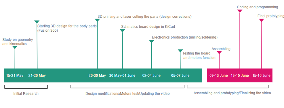
Project timeline
The following timeline diagram shows an approximate plan I had in mind from Week 16 to Week 19 (Final project presentation). Although I could not fit the actions for each step in reality, it is good to have it for a clear vision of your project and time management.