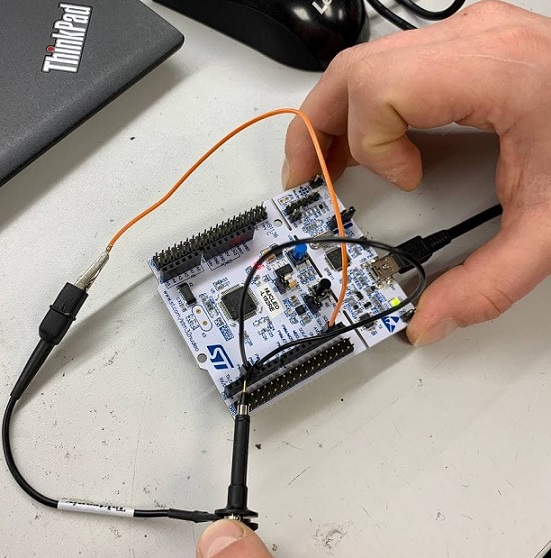
The STM32 Nucleo board is a low-cost and easy-to-use development platform used to quickly evaluate and start development with an STM32 microcontroller in LQFP64 package. The STM32 Nucleo boards integrate an ST-Link debugger/programmer, so there is no need for a separate probe.
Figure 1. Testing STM32 Nucleo-64 board
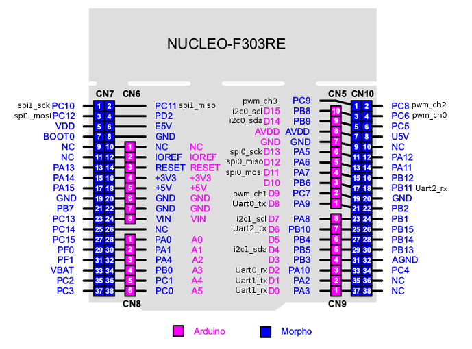
Figure 2. STM32 Nucleo-64 board pinout
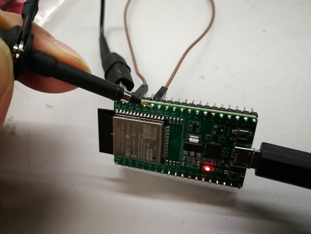
The ESP32 Dev board is a small-sized ESP32-based development board produced by Espressif. Most of the I/O pins are broken out to the pin headers on both sides for easy interfacing. Developers can either connect peripherals with jumper wires or mount ESP32-DevKitC V4 on a breadboard.
Figure 3. Testing ESP32-DevKitC V4 board
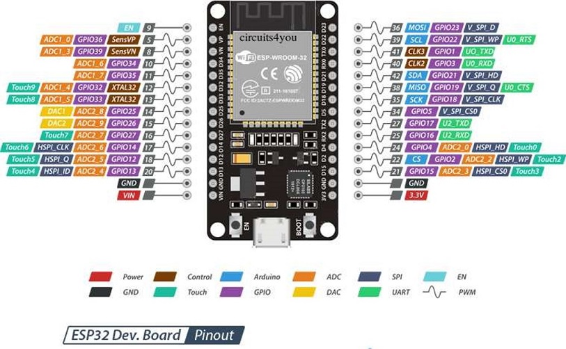
Figure 4. ESP32-DevKitC V4 board pinout
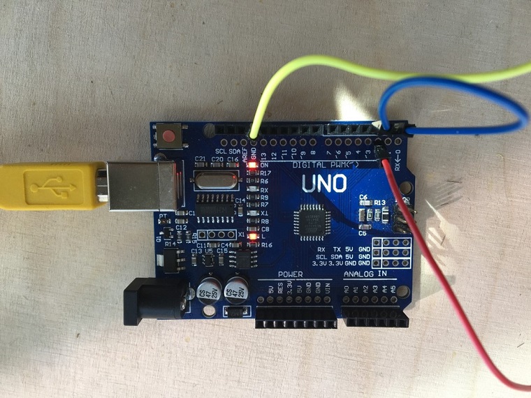
The Arduino UNO is the best board to get started with electronics and coding. The Arduino Uno is an open-source microcontroller board based on the Microchip ATmega328P microcontroller and developed by Arduino.cc. The board is equipped with sets of digital and analog input/output (I/O) pins that may be interfaced to various expansion boards (shields) and other circuits.
Figure 5. Testing Arduino Uno board
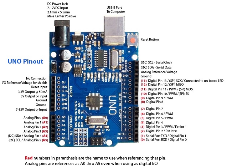
Figure 6. Arduino UNO board pinout
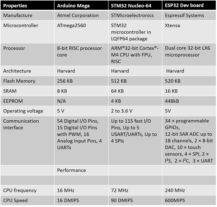
The comparison table of the main features of the tested boards and performance:
Table 1. Comparing the main features of the three tested boards
An LED-blinking test was programmed on all three development boards as following (Explanations are for STM32 Nucleo-64 board but it is similar for two others):
Connect the board to a connector USB
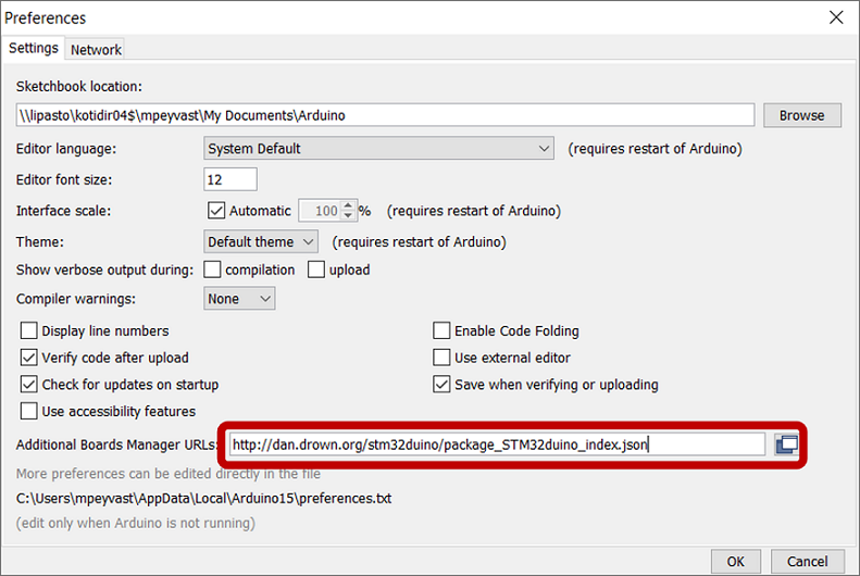
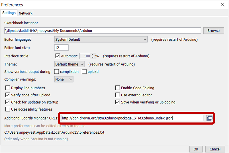
For STM32 Nucleo-64 board, we followed this tutorial to download the board to the Board Manager. Then, Launch Arduino IDE and go to File->Preferences and add the following link to the "Additional Boards Managers URLs" field and click OK:
Figure 7. Adding Additional Boards Managers URLs in Arduino IDE :
Next, go to Tools->Boards->Boards Manager, search for STM32 and then, install the board as selected in Figure 9:
Figure 8. Installing the selected board
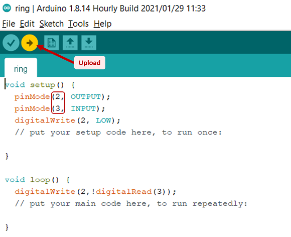
Upload the ring sketch, Verify and then, Upload the file.
Figure 9. Uploading the sketch
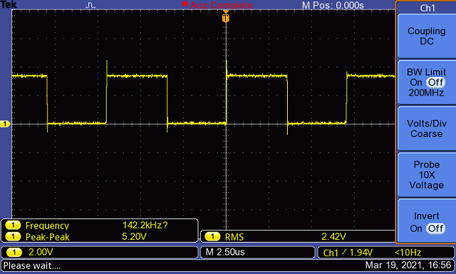
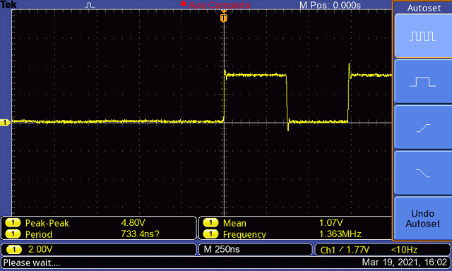
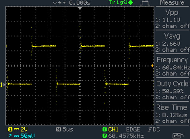
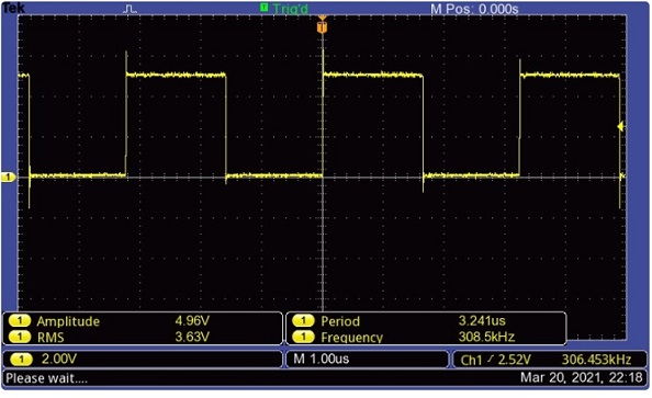
Finally, according to the pinout info for each board, we connected each board to the oscilloscope to compare their features (Figure 11-13).
Figure 10. Testing STM32 Nucleo-64 board with oscilloscope
Figure 11. Testing ESP32-DevKitC V4 board with oscilloscope
Figure 12. Testing Arduino UNO board with oscilloscope
Figure 13. Testing echohello board with oscilloscope
Individual assignment
Reading ATTiny datasheet
For this week's assignment, we should read a microcontroller datasheet and since I used ATtiny412 to make my board in Week 6, so I decided to read that microcontroller datasheet. The latest ATtiny412 datasheet has 594 pages! But I found a summary of it with only 16 pages. So I had to scan it briefly
The ATtiny412 microcontroller is using the high-performance low-power AVR®RISC architecture and has these main features:
Running at up to 20MHz
h up to 2/4KB Flash
128/256bytes of SRAM
64/128bytes of EEPROM
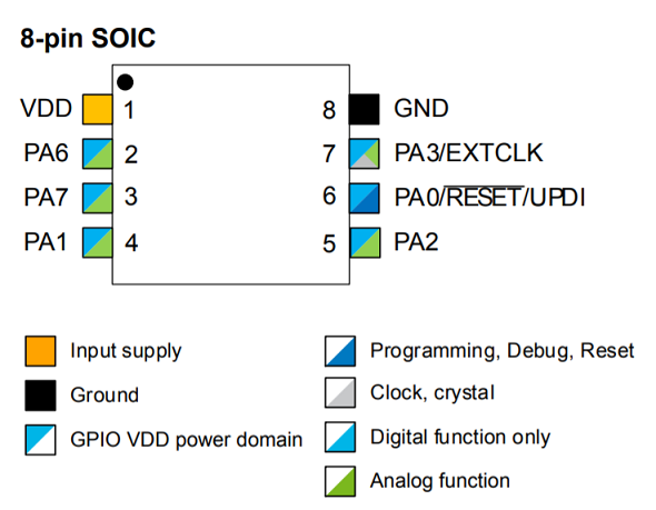
8-pin SOIC150
6 Programmable I/O Lines
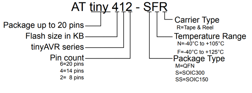
The name of a device of the series contains information as depicted in Figure 14:
Figure 14. Device Designations in ATtiny412
Figure 15. ATtiny412 pinout
Programming ATtiny412 with Arduino IDE
The open-source Arduino Software (IDE) makes it easy to write code and upload it to the board. This software can be used with any Arduino board.
To add the ATtiny44 board in Arduino IDE, I followed these steps from here to install megaTinyCore board manager :
Launch Arduino IDE, go to File -> Preferences->Additional Boards Manager URLs and enter this URL:
http://drazzy.com/package_drazzy.com_index.json
Figure 16. Setting Additional Boards Manager URLs in IDE
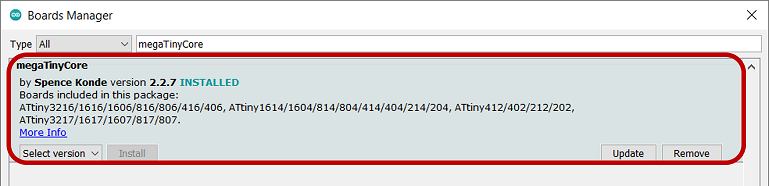
Go to Tools -> Boards -> Boards Manager, then, select "megaTinyCore by Spence Konde" and click Install.
Figure 17. Installing megaTinyCore board manager in IDE
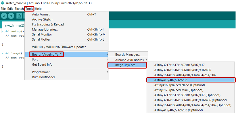
Next, go to Tools > Board:xxx and find megaTinyCore Board for ATtiny412 (Figure 18)
Figure 18. Selecting megaTinyCore board for ATtiny412 in IDE
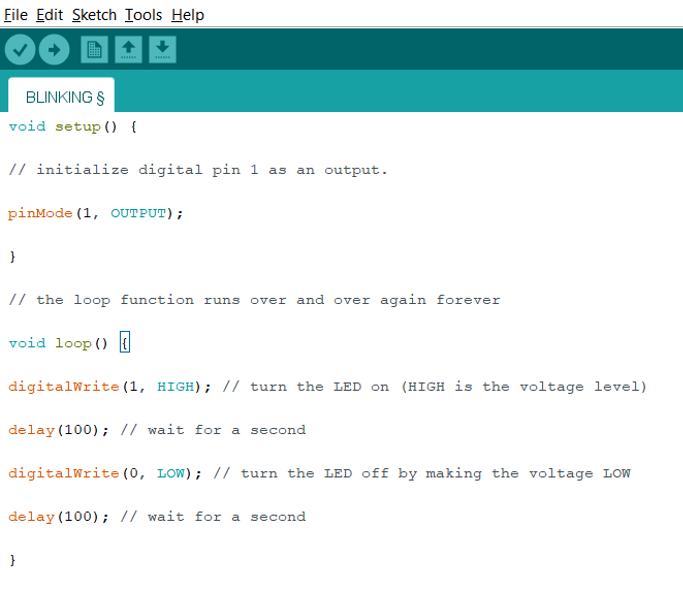
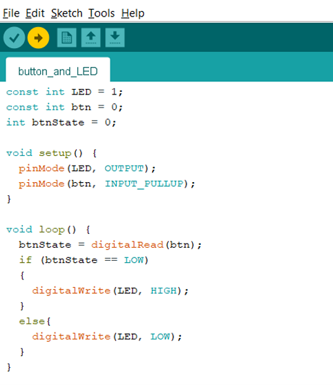
Then, I tried to write a simple code following this tutorial and conidering Output LED pin number as 1 and the Input BUTTON pin as 0 according to the Arduino IDE pin out Instruction as the following image:
Figure 19. Programming a blinking code in IDE
But I faced this error:
avrdude: ser_open(): can't open device "\\.\COM4": The system cannot find the file specified.
The setting I have used for this sketch is shown in Figure 20. As you can see, Port setting was inactive and I could not edit it as suggested in solution pages.
Figure 20. Settings of the first sketch in IDE
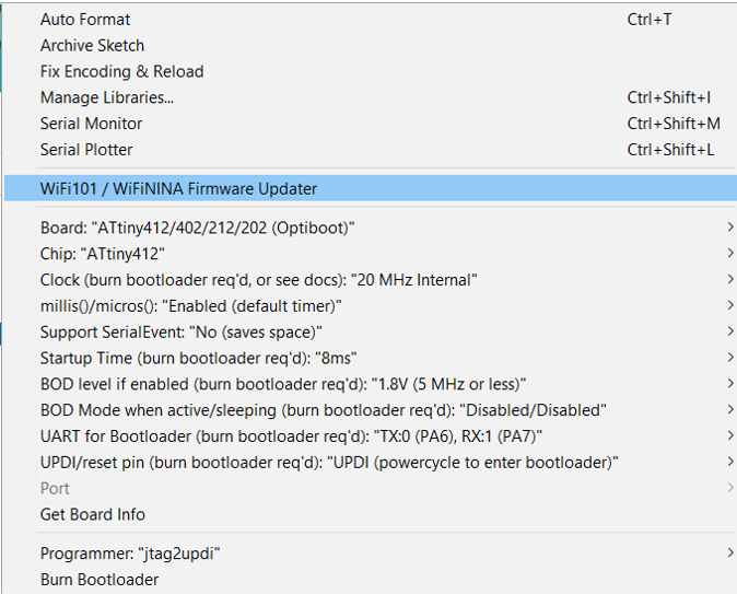
So, I asked our instructor, Gleb, for the help with that. First, he asked me to change the LOW voltage pin to 1 in order to have the output from one pin, then, change the borad to megaTinyCore->ATtiny412/402/212/202 and finally, choose COM4 from Port. It worked and thanks to him!
Programmed blinking board with Arduino IDE
Then, Gleb helped me to activate the button on my board by using this simple skecth on IDE:
I did not have any experience with embeded programming before, so during this week, I learned the basics of programming with Arduino IDE for different boards according to their pinout.