Week 10
Individual assignment- add an output device to a microcontroller board you've designed and program it to do something
For my project there are two types of outputs I will use: audio and scent. The first one is quite hard to implement for now, this is why for this week I focused entirely on the second output which is to be done through a motor. I was working still remotely using Arduino Uno starter kit. So I tried a dc motor and a servo motor. Truth to be told, I did not have much knowledge about motors in general, for this reason I did a little research on it.
Servo motor
So I got started with a servo motor that is a motor that can rotate only to 180 degrees and controlled by electrical pulses sent from Arduino board which specifies the position of servo to take.
I used the following components:
- (1) x Elegoo Uno R3
- (1) x Servo (SG90)
- (3) x M-M wires (Male to Male jumper wires)
The code implemented permits to move the servo to 90 degrees, then to 60°, then 90° again and 120°.
#include/* After including the corresponding libraries, we can use the "class" like "Servo" created by the developer for us. We can use the functions and variables created in the libraries by creating objects like the following "myservo" to refer to the members in ".".*/ Servo myservo; //it created an object called myservo. /* you can see Servo as a complex date type(Including functions and various data types) and see myservo as variables. */ void setup(){ /*"attach" and "write" are both functions, and they are members contained in the complex structure of "Servo". We can only use them if we create the object "myservo" for the complex structure of "Servo". */ myservo.attach(9);//connect pin 9 with the control line(the middle line of Servo) myservo.write(90);// move servos to center position -> 90° } void loop(){ myservo.write(90);// move servos to center position -> 90° delay(1000); myservo.write(60);// move servos to center position -> 60° delay(1000); myservo.write(90);// move servos to center position -> 90° delay(1000); myservo.write(150);// move servos to center position -> 120° delay(1000); }
And this was the result:
DC Motor
As the tutorial to Arduino kit specifies if I were to connect DC motor directly to Arduino it would damage the board, because when I switch a motor off I get an electrical feedback that's why it was necessary to use a power supply module. As seen in the Bill of materials below the kit provided also for a half-H driver L293D that permits to control up to 2 motors at the same time and provides bidirectional drive currents of up to 1 A at voltages from 4.5 V to 36 V. Since I've had just on, I used half of the pins of this chip.
I used the following components:
- (1) x Elegoo Uno R3
- (1) x 830 tie-points breadboard
- (1) x L293D IC
- (1) x Fan blade and 3-6v motor
- (5) x M-M wires (Male to Male jumper wires)
- (1) x Power Supply Module
- (1)x 9V1A adapter
I used the following code from the kit's tutorial that tells the motor to move in one way, then reverse, stops. Then goes one way, stops slowly, goes one way and stop rapidly. Then it goes only half speed.
#define ENABLE 5
#define DIRA 3
#define DIRB 4

int i;

void setup() {
  //---set pin direction
  pinMode(ENABLE,OUTPUT);
  pinMode(DIRA,OUTPUT);
  pinMode(DIRB,OUTPUT);
  Serial.begin(9600);
}

void loop() {
  //---back and forth example
    Serial.println("One way, then reverse");
    digitalWrite(ENABLE,HIGH); // enable on
    for (i=0;i&l5;i++) {
    digitalWrite(DIRA,HIGH); //one way
    digitalWrite(DIRB,LOW);
    delay(500);
    digitalWrite(DIRA,LOW);  //reverse
    digitalWrite(DIRB,HIGH);
    delay(500);
  }
  digitalWrite(ENABLE,LOW); // disable
  delay(2000);

  Serial.println("fast Slow example");
  //---fast/slow stop example
  digitalWrite(ENABLE,HIGH); //enable on
  digitalWrite(DIRA,HIGH); //one way
  digitalWrite(DIRB,LOW);
  delay(3000);
  digitalWrite(ENABLE,LOW); //slow stop
  delay(1000);
  digitalWrite(ENABLE,HIGH); //enable on
  digitalWrite(DIRA,LOW); //one way
  digitalWrite(DIRB,HIGH);
  delay(3000);
  digitalWrite(DIRA,LOW); //fast stop
  delay(2000);

  Serial.println("PWM full then slow");
  //---PWM example, full speed then slow
  analogWrite(ENABLE,255); //enable on
  digitalWrite(DIRA,HIGH); //one way
  digitalWrite(DIRB,LOW);
  delay(2000);
  analogWrite(ENABLE,180); //half speed
  delay(2000);
  analogWrite(ENABLE,128); //half speed
  delay(2000);
  analogWrite(ENABLE,50); //half speed
  delay(2000);
  analogWrite(ENABLE,128); //half speed
  delay(2000);
  analogWrite(ENABLE,180); //half speed
  delay(2000);
  analogWrite(ENABLE,255); //half speed
  delay(2000);
  digitalWrite(ENABLE,LOW); //all done
  delay(10000);
}
This is the result:
As my instructor told me, for my final project I would not need to change the direction of the motor's movement. In fact, it would have been easier for me just to take Neil's circuit with H-bridge, but I drove into dc motors' circuits that turned out to be more complex than I had imagined. The basics about this type of circuits and motors in general I grabed from here and here. As also during the output class Neil says there is no need of 4 transistors as in H-bridge, but just one if you don't want to change the motor's direction. So I figured out that I would need MOSFET transistor of N type, that works roughly said as a switch enabled from sofware where the button on and off is regulated through the pin called GATE. A bit more about MOSFET I learned from this video and about transistors in general from this one.
I tried to create a schematic using a DC motor and putting a MOSFET transistor of type N, but it was a wrong try. The schematic is below, I will try to figure it out eventually.
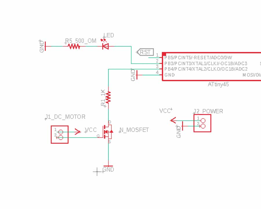
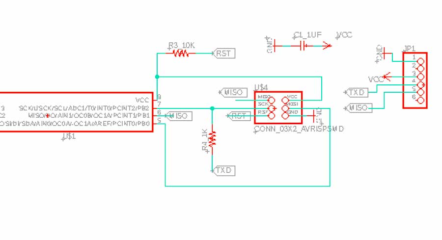
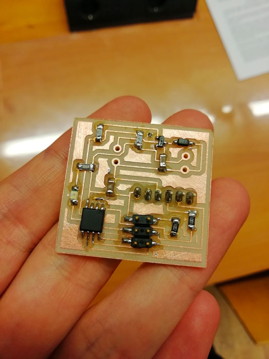
One of my doubts regarded the necessity of an extra capacitor and our instructor explained me that this so-called decoupling capacitor is needed in every board for every couple of VCC and GND to keep the power supply costant and without interruptions. So in my board I would need two resistors for DC motor part where one of 100 OHM value has the function to protect the microcontroller in case MOSFET were to burn, while the second is a pull down 1M OHM resistor. SOURCE goes to GND, DRAIN pin is to connect to the motor. As you can see in the schematic below next to the motor there is also a diode called flyback diode, its function is to protect mosfet when the motor stops working due to the effect generated by inductance that can come back to mosfet and burn it when it stops receiving current.
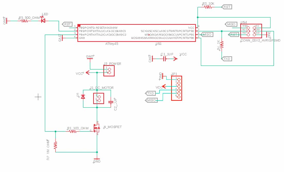
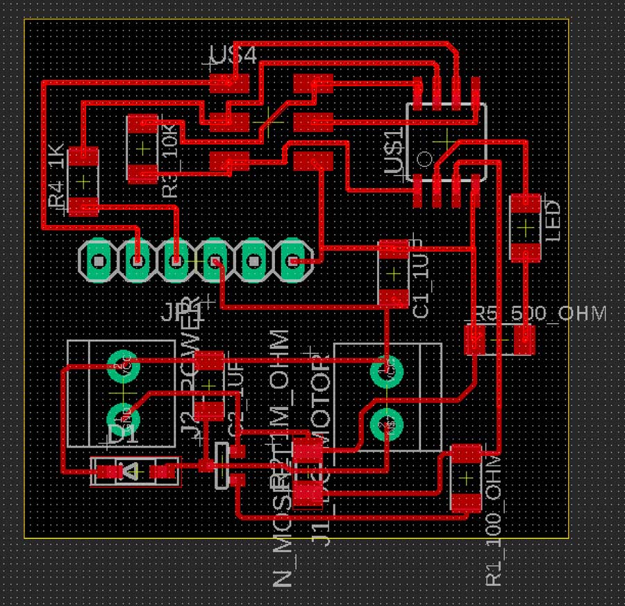
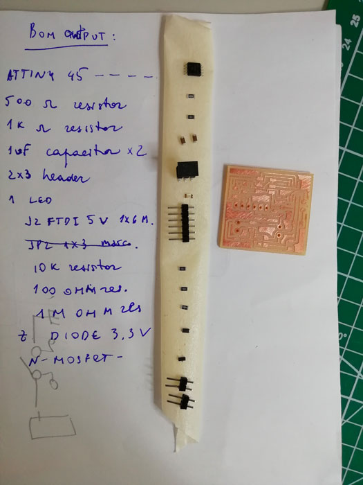
I left some extra terminal blocks in order to be used to connect a PIR or another motor. I still need to check whether my PCB functions or not.
DC motor in action
I programmed my PCB to blink the Led, but this week assignment as also my board turned out to be useful during machine design week in our group project, since for the tower we designed, we used DC motor for the movement.
Docs
You can download the zip package with files of this week from here.