Week 12
Group assignment
- design a machine that includes mechanism+actuation+automation
- build the mechanical parts and operate it manually
- document the group project and your individual contribution
Project idea
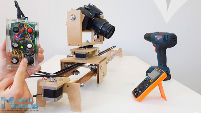
Doing the research to find an idea to implement for this project we eneded up on the howtomechatronics website. Firstly, we decided to build a Motorized Camera Slider following this tutorial. After a while, one of my colleagues proposed to construct a lamp that would be actually a Sauron Tower from Lord of the Rings. It seemed to be more original and fun to do, especially for a "wow effect" that we expected to get from this project. But "wow effect" we got mostly when something was not working lol
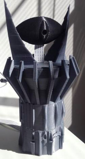
So these were the project proposal that we found. The top of this tower lamp would have a light, inside of the eye and the whole part can be moved in vertical direction: up-down by a servo motor and in horizontal: right-left by a DC motor.

Design
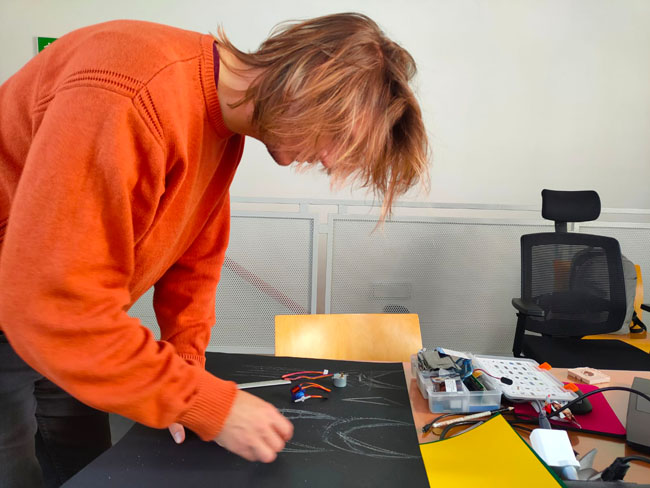
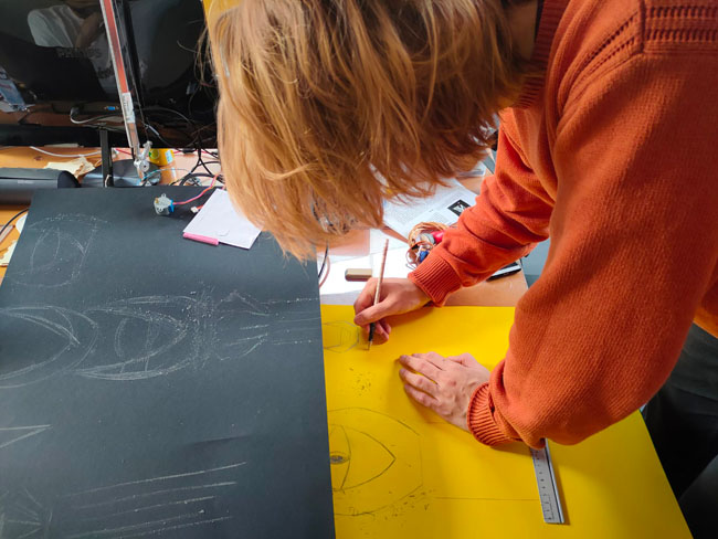
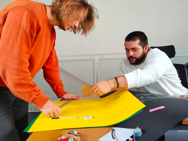
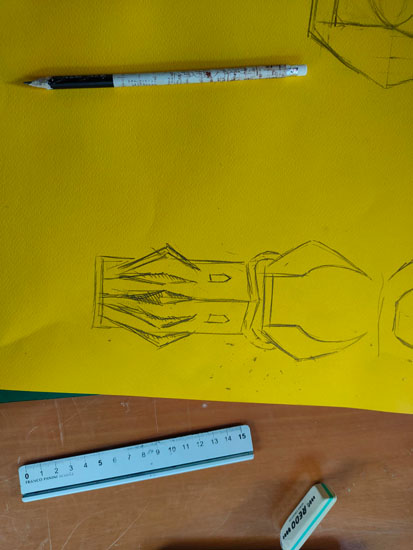
After a brainstorming with my colleagues about the structure and future location of motors & Leds I tried to figure out on paper the dimensions of our project in order to understand how big and tall the tower/eye would be. So I just roughly misured servo motor that is to be placed in the "head" of the eye. I did not calculate the thickness of wood, there was my error. Overall, it is worth to build something a bit bigger rather than just right. Although I chose the latter. In fact, it'd have been better to check eventually the measurements directly on Fusion360. At this point though we tried to understand also just how it would look like in real life.
3D model
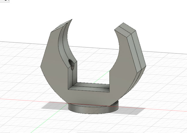
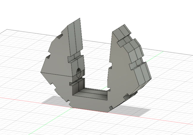
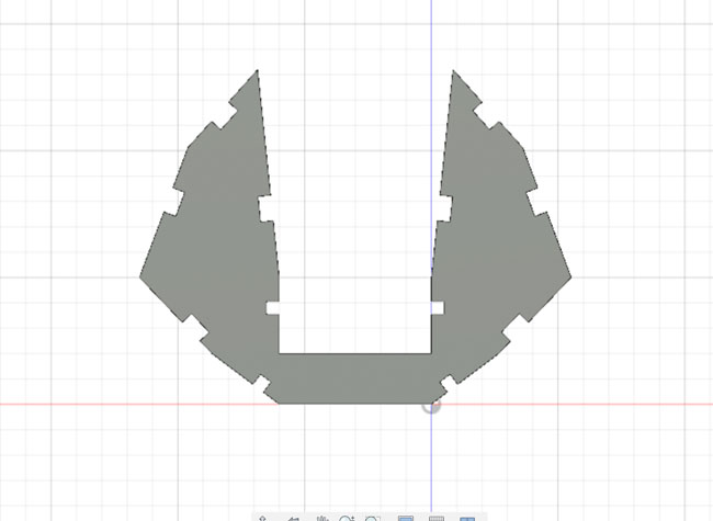
After the preparation with one of my colleages Alberto of the first 3D model of the top part, we decided to build it in wood to accelerate the timing basically, laser cutting it. So the curve part was nice to see, but impossible to realise.
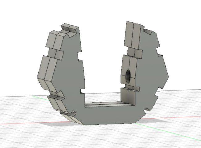
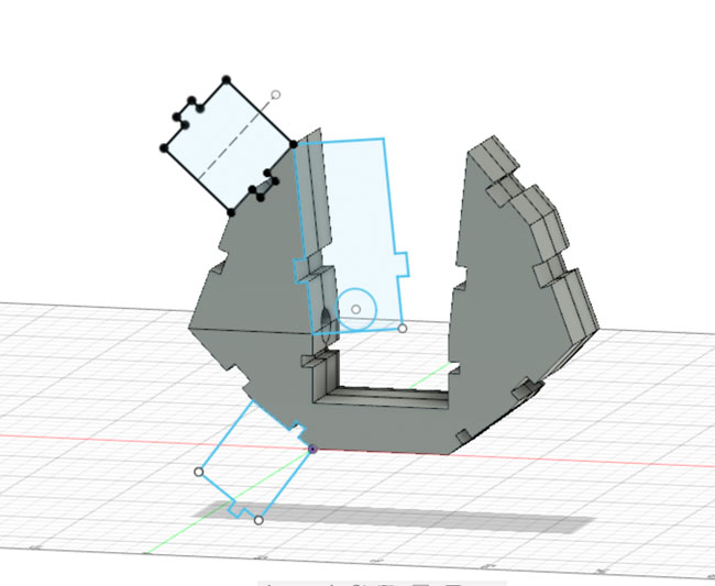
This is why I proceeded with modifications of this moder in order to one proper for laser cut. I modified it several times, as told before, because I had to increase space between two sides, as servo motor could not fit and I didn't take into account wood thickness and issues with joints. Moreover, I chose simply puzzle like joints considering the kerf, even though to be sure we would use glue to keep everything together. My solution for joint modelling on Fusion is quite ugly, but it worked :D
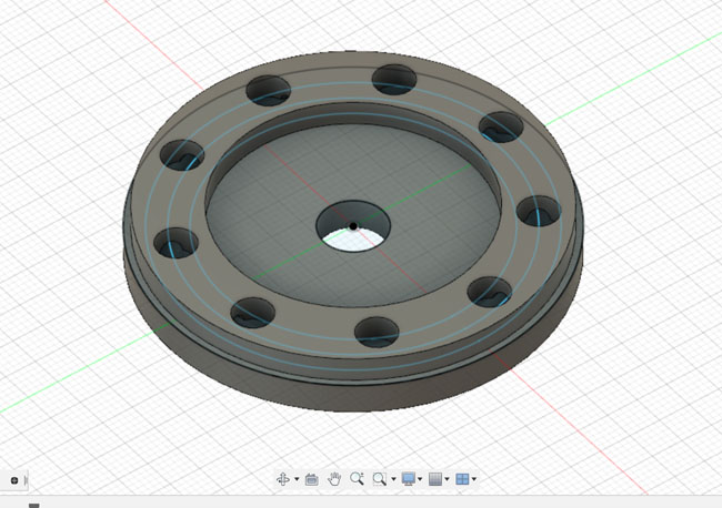
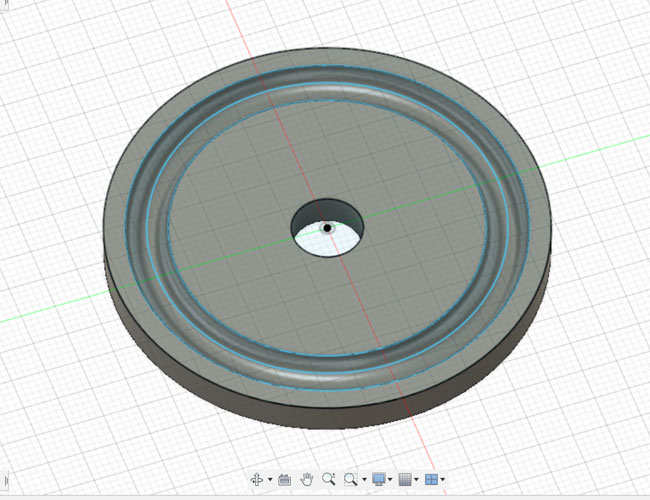
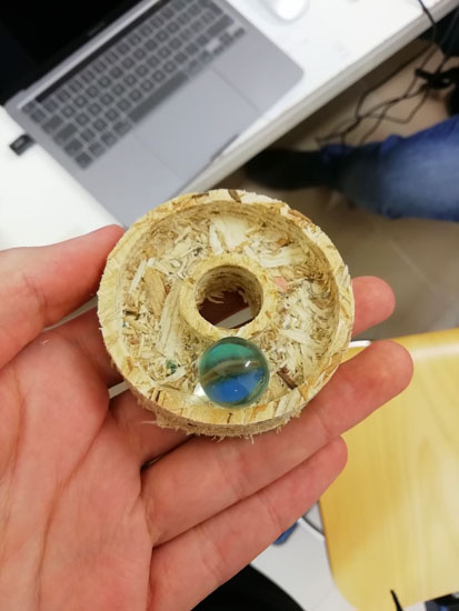
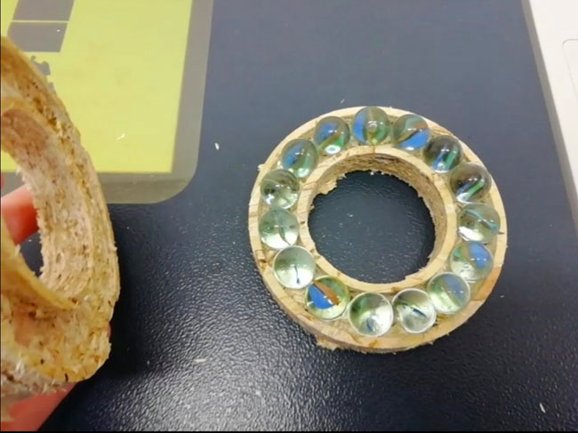
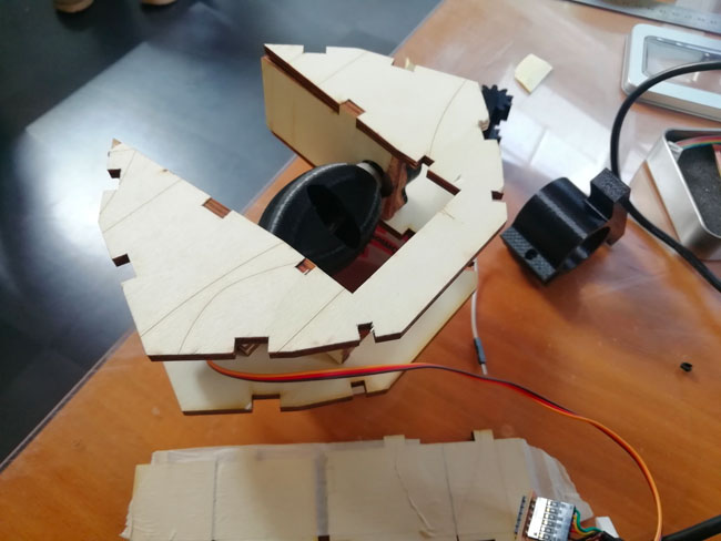
Thrust bearing
This system is a type of rotary bearing that permits to permanently rotate between parts. I designed it on Fusion360 considering that the top part would be done separately. Although our instructor told us that is was faster and more doable with ShopBot that we don't know how to use yet, so he gave us a hand with that. The first try did not work out, because the bearing was too small as seen in the picture below. So the second time it was cut on a bigger scale.
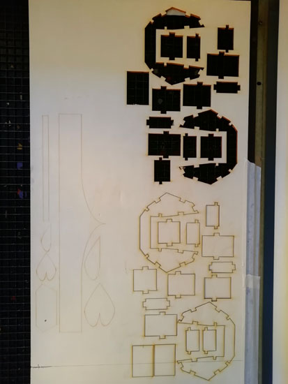
Laser cut
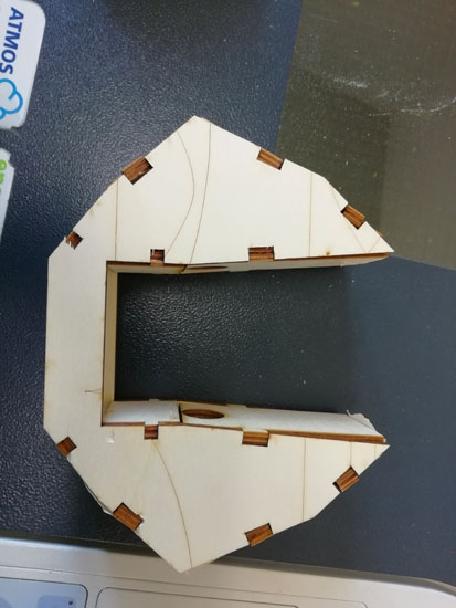
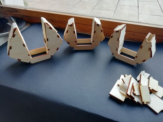
Overall, I laser cut three times the "head" where the eye was placed. The first time there was a problem with joints that were too tight and did not fit or did with a lot of forse applied. The second time was ok, but when I placed the servo inside of it the side parts would not close properely: too little room. Therefore, the last time did not I just enlarged the space, that is the side parts with joints, but also made the whole structure higher, it just looks cooler:)
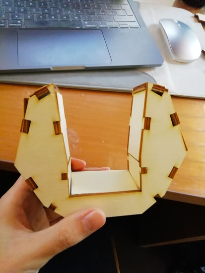
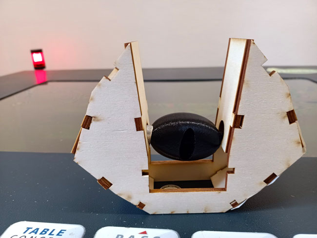
Assembling
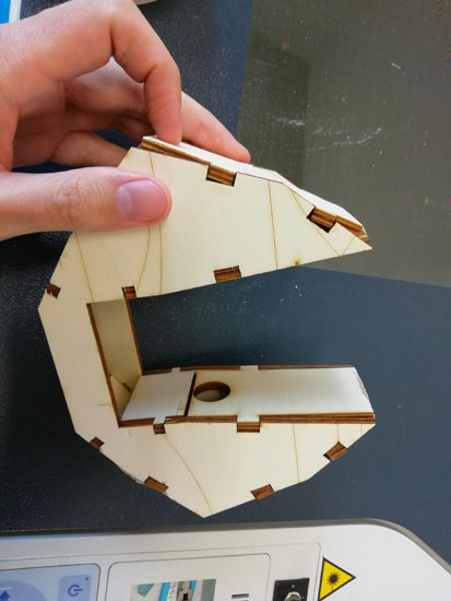
Once figured out the space needed for servo motor, the time arrived to put it in place. I found a really fancy solution just using two pieces of wood, old joints, and adding some glue on it. Fortunately, it did work and that is important.
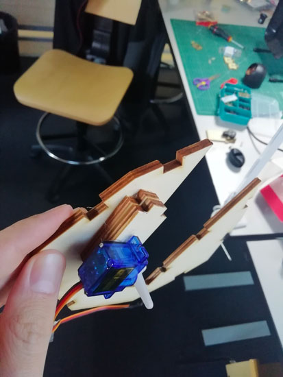
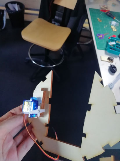
So we connected the wires and checked if actually servo motor was able to move the eye. The latter is pretty light, so there were little doubts about that. The main issue was friction, that's why it was crucial to find right position for the eye and holders that kept it glued on both sides.
See the development of this project on this page.
Docs
top tower1
bearing
top tower2 and joints