Week 15
Individual assignment: write an application that interfaces a user with an input and/or output device that you made
Python intro
So this week I decided to learn programming in Python. Since it's quite impossibe to learn in just some days, I focused on specific functions that may be useful for building an interface.Python is a popular language that is used for web development, system scripting and even for math. It is a versatile tool to create webpages and applications, database systems, workflows etc.
One of the main differencies that I noticed basing on my scarse and little knowledge in this field is that Python's syntax is strict when it comes to spacing when writing the code and it is not used just to make the lines more readable. It is called indentation, that is spaces in the beginning of a code line. indentation in Python is necessary to specify a code block, so inside of it the same space must be used. Otherwise it will give errors. Number of spaces in every code line is up to you, the minimum is 1. For example, this code would not work because in the print line space at the beginning is missing. if 1 > 0:
print("One is greater than zero")
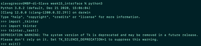
On MacOS python is already preinstalled, it is important though to specify version when writing the code. So in the command line it is recommended to write "python3" rather than just "python" since a lot of operating systems have previous versions pre-installed on them. For example, on mine python2 and python3 co-exist. Moreover, it kept giving me errors saying that my version is obsolete and in fact, some features were not working properly or not working at all. Hence, I installed python again from official website. I also checked the framework tkinter if it was working well.
Coding
Mainly I used w3schools tutorials, since I've got used to the format and like it. There apart from the first intro steps and tutorials, I read also about if statements that are different in Python also for the presence of elif keyword that means "if the previous conditions were not true, then try this condition", while and for loops.
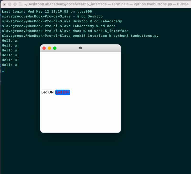
Then I watched this, this and this tutorial among others about creation of GUI interface with Python. The methods used are more or less similar one to another, so summing up I used this code for creation of two buttons, without any link to PCB yet.
  from tkinter import * #import of tkinter framework

  root = Tk() #creation of the root window
  root.geometry('300x300') # set a size for the window and position it on the screen

  def buttonFunction(): #define function button
      print("Hello u!")

  b = Button(root, text="Led ON", command=buttonFunction, activeforeground="red") #creation of the button, show on display and write Led ON applying the function above, when pressed color it with red
  b.pack(side=LEFT) #this geometry manager organizes widgets into horizontal and vertical boxes

  b2 = Button(root, text="Led OFF", command=buttonFunction, activeforeground="red")
  b2.pack(side=LEFT)

  root.mainloop() #event handling starts from this point.
And this is not particularly nice, but working result.
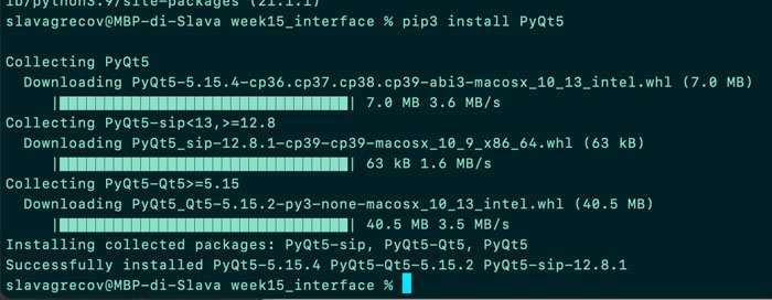
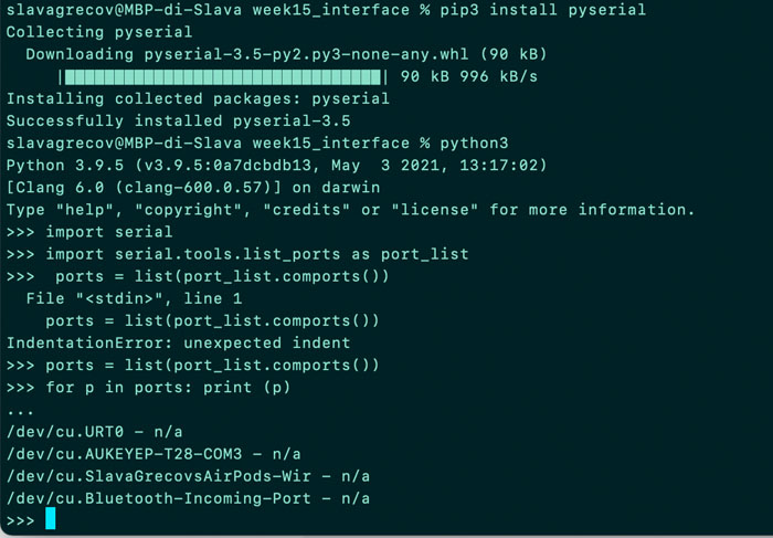
After that I installed frameworks that I needed and finally I asked to show me available ports on my computer as reported on the screenshots below. In otder to link python with serial port I needed to import serial.
  import sys
  import serial
  from PyQt5 import QtCore, QtWidgets
  from PyQt5.QtWidgets import *
  from PyQt5.QtWidgets import QPushButton
  from PyQt5.QtCore import QSize

  ser = serial.Serial('/dev/cu.URT0', 9600)

  #define general characteristics of the interface
  class App(QWidget):
      def __init__(self):
          super().__init__()
          self.title = 'Interface' #title's creation for the window

          self.initUI()

   #Add 2 buttons that make the function "ledOn" and "ledOff"

      def initUI(self):


          button = QPushButton('Turn Led ON', self)
          button.clicked.connect(self.LedON)
          button.move(100,120) #specify the dimension of buttons
          button.resize(110,32)

          button2 = QPushButton('Turn Led OFF', self)
          button2.clicked.connect(self.LedOFF)
          button2.move(100,160)
          button2.resize(110,32)


          self.show()

  #def functions define what ledOn does once the software buttons are pressed

      def LedON(self):
          #print(ser.name)   #debug
          print('Led On')
          ser.write(b'1')

      def LedOFF(self):
          print('Led Off')
          ser.write(b'0')


  if __name__ == '__main__':
      app = QApplication(sys.argv)
      ex = App()
      sys.exit(app.exec_())
First try
Then I wrote a code for Arduino that then I uploaded on the board.
  #include <SoftwareSerial.h> //import serial communication library


char c; //data type used to store a character value, that is 1 or 0 in this case
int myLed = 3;
SoftwareSerial newSerial(2,1); // set up a new serial object with RXpin and TXpin

void setup(){
pinMode(myLed,OUTPUT);
newSerial.begin(9600); //enable serial communication, sets data rate to 9600 bps
}
void loop(){

delay(200);

if (newSerial.available()>0){ //get the number of bytes arrived and stored in the serial receive buffer
  c = newSerial.read(); // return 1 or 0 that were received on the RX pin of the software serial port

  if (c=='1'){    // // reply only when you receive data
   digitalWrite(myLed,HIGH);
  }
  if (c == '0')
  {
   digitalWrite(myLed,LOW);

  }
}
}
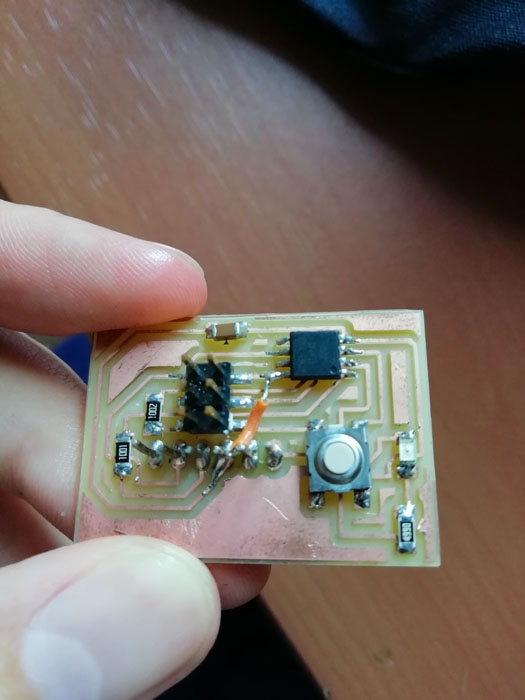
Since I was at home and did not have all the materials needed, I tried first with Arduino and unfortunately untill now it's the only try that worked lol For some unknown reason with 2 of my PCB's that is hello_board and the PCB from the output week, the interface still works, so I can see Led ON and Led OFF printed on terminal, but the Led itself does not light up. So I will have to figure out the problem later on.
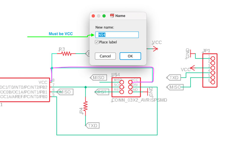
Second try
Basically, one of my VCC traces of FTDI was not labeled in the schematic on Eagle, that means that there was no power supply to FTDI, but the rest of the board could work. For example, I could light up the Led through ISP, but could not stabilise serial communication through FTDI. So my instructor who helped me with the debug, suggested me to put a small wire on my board to create this VCC missing path instead of re-doing the whole board again. This issue was really hard to find out, because in my head when I connect a VCC to another VCC it must also change the label, but apparently it does not. For this reason, I was happy that I tried my code on Arduino, so I was sure that software part was fine and for the same very reason it was strange to see my PCB not working.