Week 18
Group assignment:
- Test runout, alignment, speeds, feeds, and toolpaths for your machine.
- Document your work (in a group or individually).
Individual assignment:
- Make (design+mill+assemble) something big.
Group assignment
Feed rate/climb/conventional
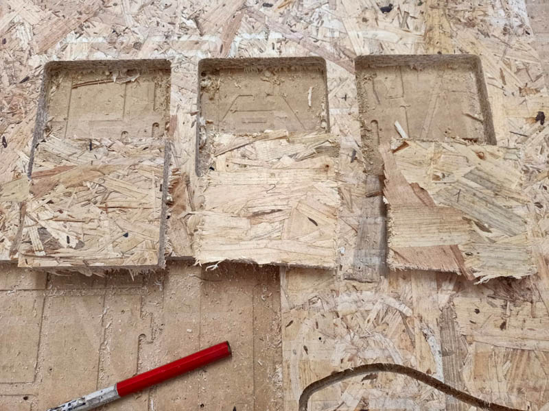
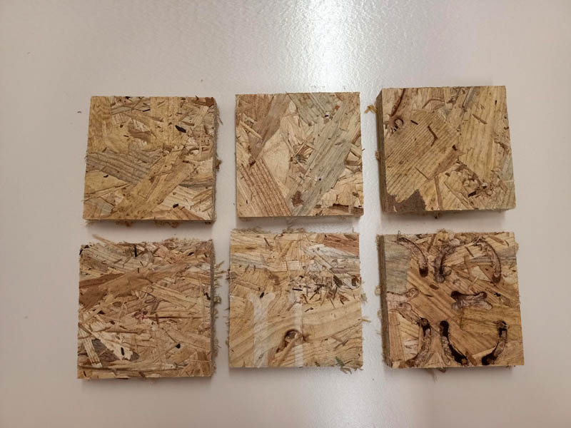
After an introduction about safety rules while working with shopbot, we proceeded with group project and studied more profoundly about feed rate, in other words, it is a value that indicate the speed with which the drill moves forward against the material in horizontal direction. We tried three feed rates: 90, 110 and 130. And then also cut directions, that is climb and conventional. In the pictures below it will be shown the first line cut with climb and the second with conventional. We noticed that the best rate is 100, while for the direction considering the type of wood used there was not such a big difference.
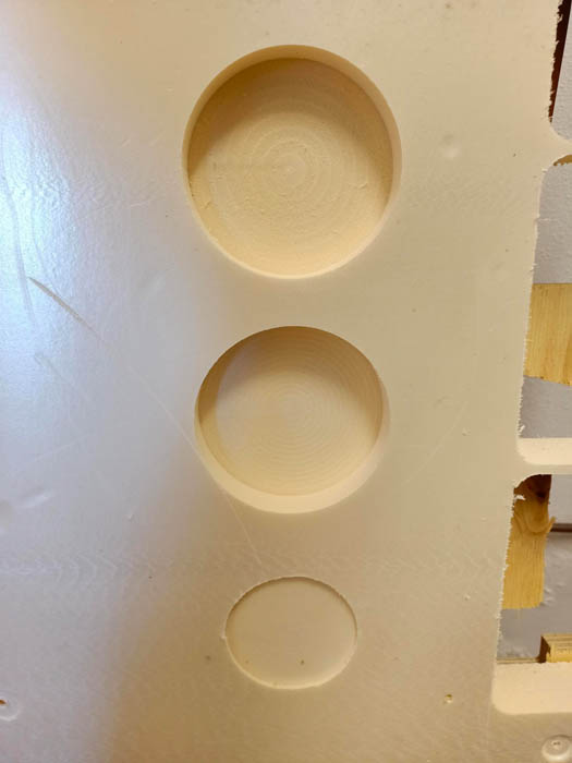
Chip load/Stepover/Pockets
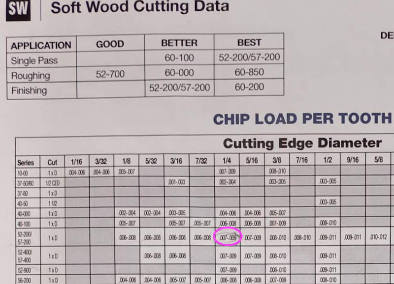
Doing a brief research we found a chip load basing on the parameters of our CNC and the drill.
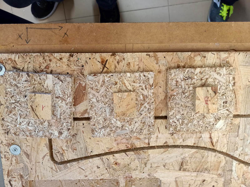
Then we defined stepover that indicates the space that is left between every pass of the drill on the surface. It is suggested to use the stepover value that is half of the tools' diameter. On a foam we tried the difference between 20%, 50% and 90% stepover and as you can see the higher value of stepover has not the same smooth effect as a low value.
Individual assignment
3D design
I needed a table for my room cause it has some free space, that's why I decided that I will do it using our CCM machine - ShopBot. I have never made any furniture by myself, so I skethed first my ideas..this time my drawings were not so nice to publish here lol
I wanted to build something simple and stable, max to put some plants on the surface. So I designed a chair-shape table on Fusion360
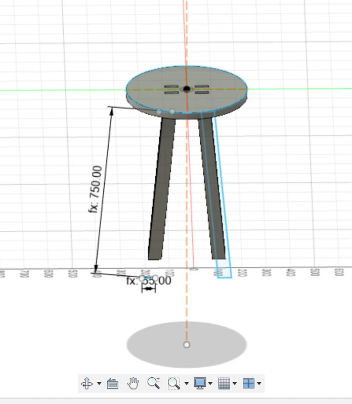
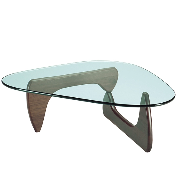
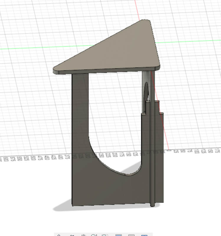
As it can be seen in the pictures, I noticed in the process that this table could never be stable or just stand. After previous research I preferred to focus on this style below that I found, but modifying a bit design of it, also because we cannot use glass for surface :)
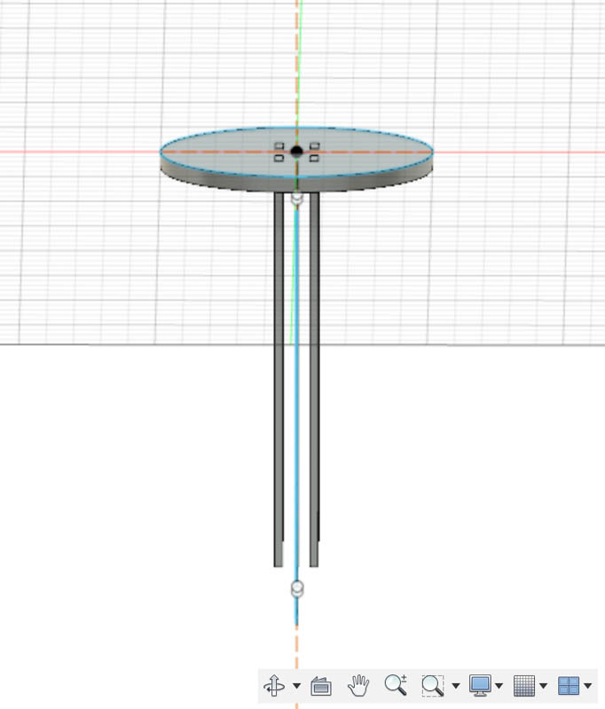
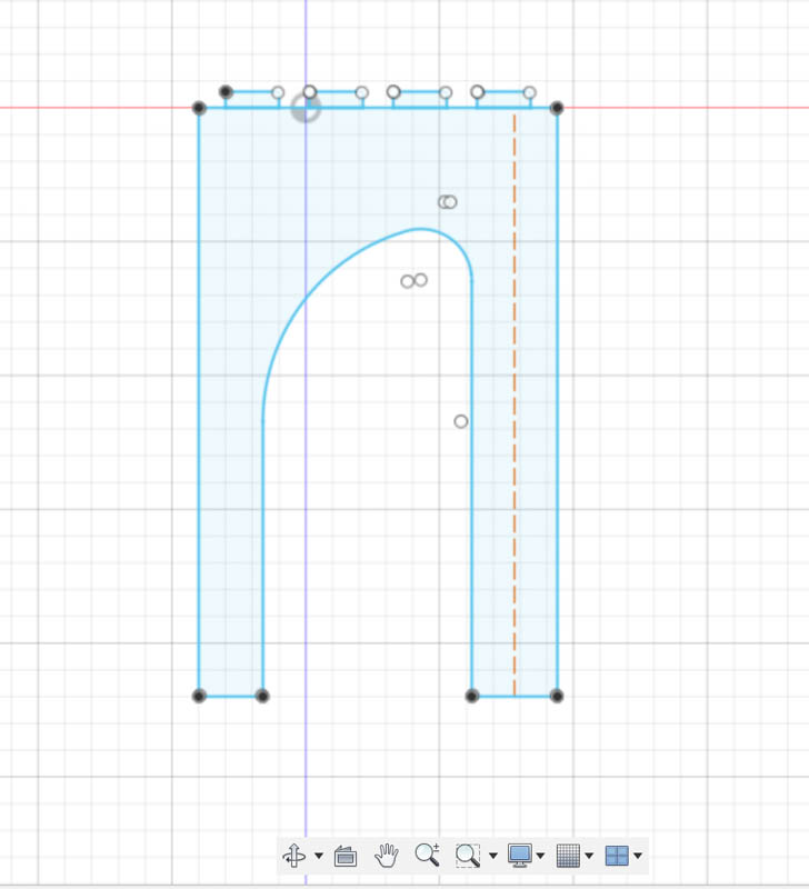
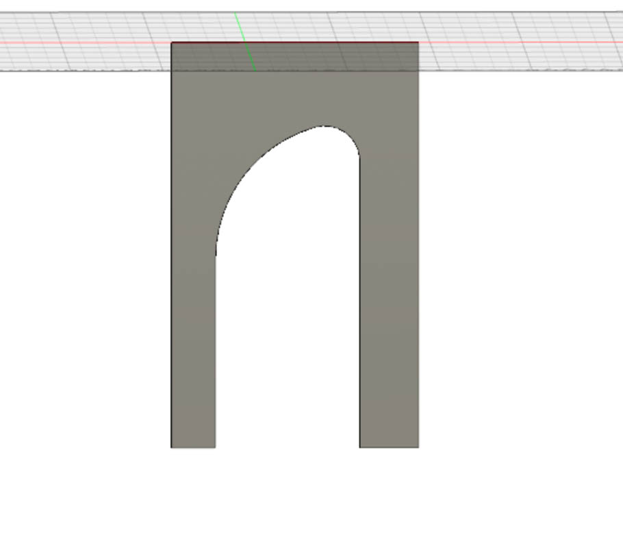
First I drew the first leg of my table.
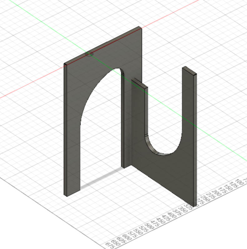
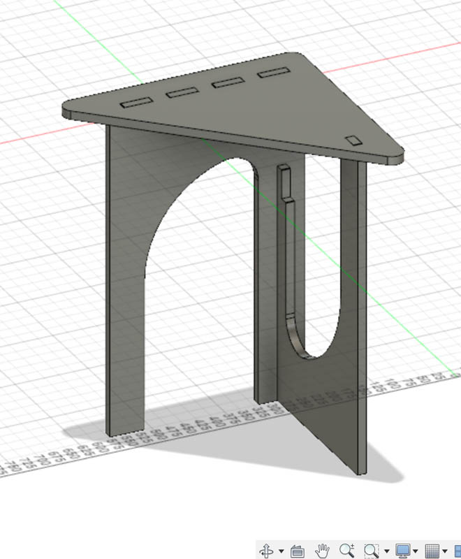
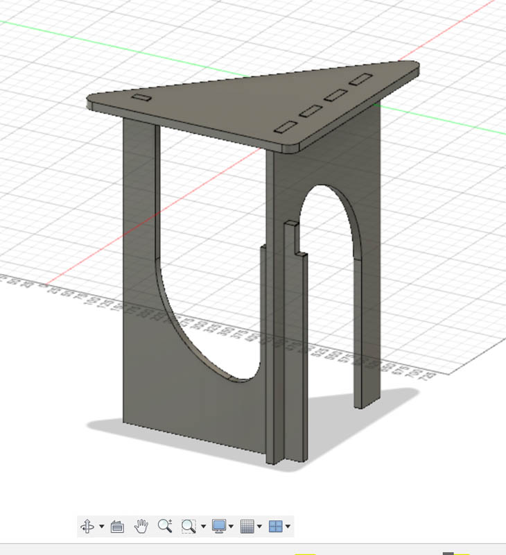
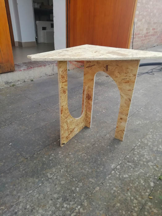
Then I created the second leg and put them together. When I added the table surface on them, I realised that it is impossible to keep the same distance for every side of it as it was in the style I had found, because it would not reach one of the legs. For this reason I modified it making a kind of right triangle. Moreover, to add more stability I created a cross joint between two legs.
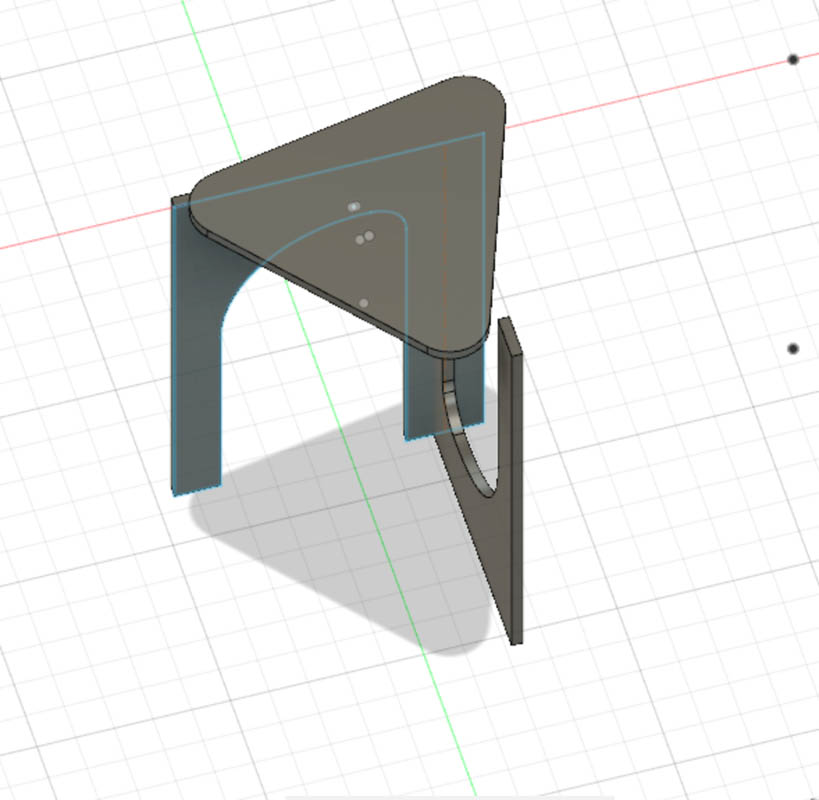
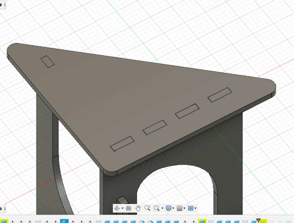
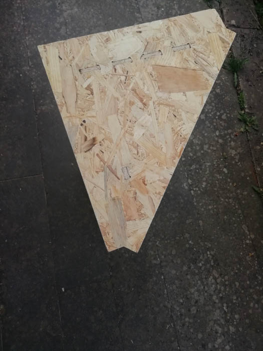
Later, I added joints on the surface too and my table was ready to be materialised!
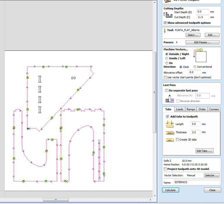
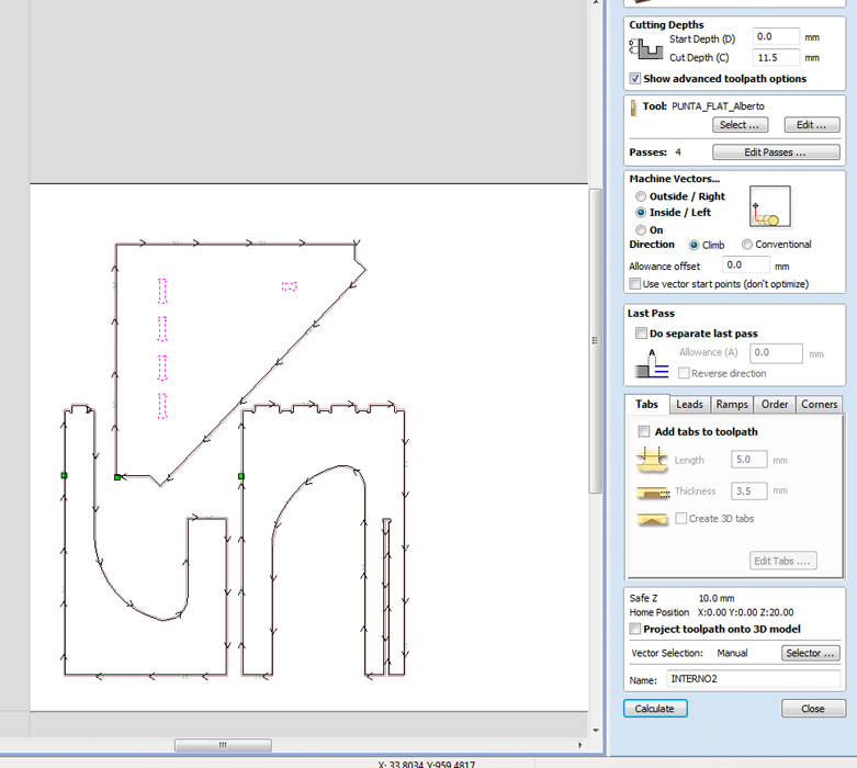
VCarve Pro
After group project we identified the parametres for the tool, so all of us used the same one: End mill, Diameter 0.25 inches, Pass Depth 0.2, Stepover 0.15 60%, Spindle speed 12 000, Feedrate 90.0, Plunge rate 10.0, Tool number 2. I set tabs, ramps and t-bones and these are the parameters I used for milling.
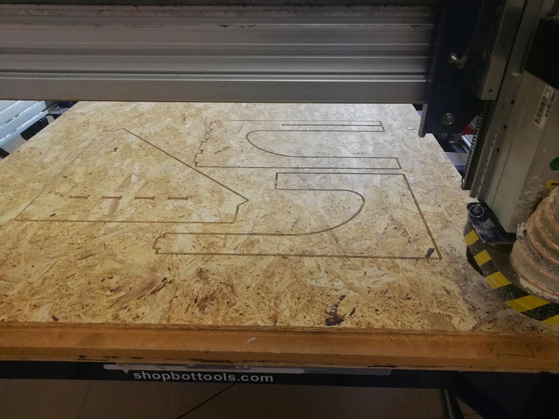
I set up X,Y and then automatically Z axes. After I raised up a bit the spindle and started the mill without actually milling to see if the drill would touch spikes or not. Everything was ok so then I went on.
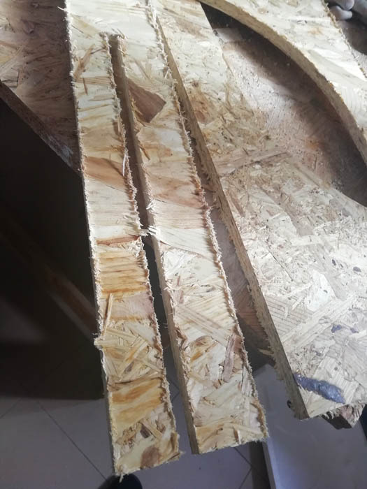
Since the wood was not exactly plain, I had to repeat milling a couple of times on two legs specifically in order to take it off smoothly.
I needed to finish a bit this wood, so I used sandpaper and a file.
Before milling I decided to extrude a bit the top surface, so I don't have exact angles, but this strange shape that makes people ask me if the table is broken. Let's say it's a design decision, questionable decision, but most importantly my table stays on its "feet"!
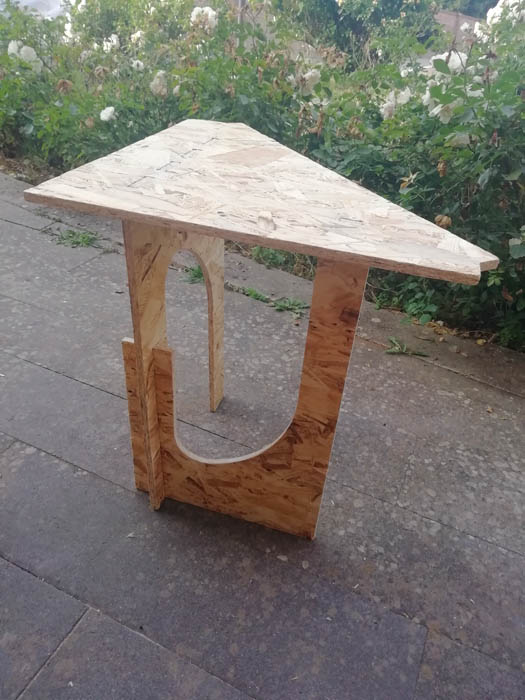
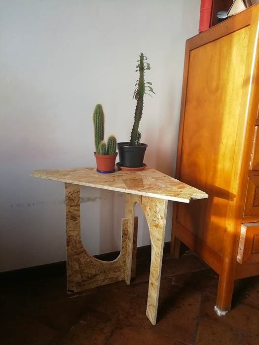
And voilà the table with my cacti :)
Docs
Download a whole zip package of stl, dxf and vcarve pro files from here