Week 4
Group project- Characterize the design rules for your PCB production process: document feeds, speeds, plunge rate, depth of cut (traces and outline) and tooling.
- Document your work (in a group or individually).
You can find our project here
Individual assignment
Make an in-circuit programmer by milling and stuffing the PCB, test it, then optionally try other PCB fabrication process.
PCB milling
To build a programmer I used the documentation for FabTinyISP
Mods
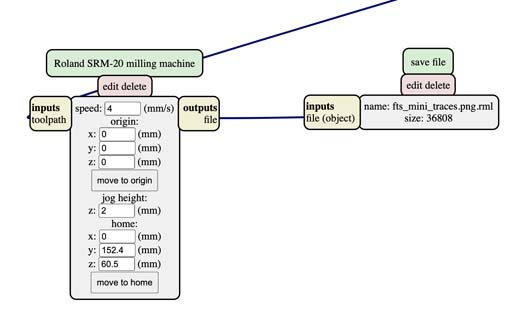
I used PCB png mode, files and the full description you can find in the documentation cited before. On the mods page do as follows: right click> programs > open server programs > Roland > SRM-20 > PCB png Then click on select png file, insert your png black and white file and check for dpi that must be around 1000 or higher.
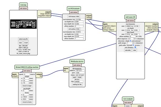
Then on set PCB defaults select mill traces. Now, the documentation used suggests modify offset number to 5 in order to get rid off a small line of the extra copper next to the USB portal. I must say that in my case it didn't work and anyway I cut it out with a knife. So you can leave the number 4 as well. Here you can calculate and view if that path is correct and corresponds to the image imported.
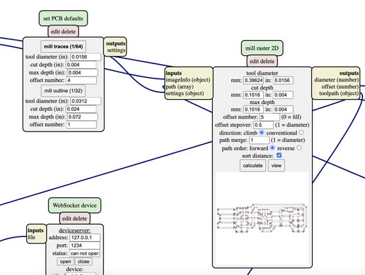
Modify the setting of the origin to x: 0 y:0 z:0 and in case you are working on the computer that is not connected directly to the milling machine delete WebSocket device and right click on the screen>module > open server modules > file > save connect it to the setting of you milling machine, here to our Roland. Now you can save your file in .rml format. Do the same for the outline using mill outline on the set PCB defaults, here the offset number is 1.
Milling
One of the main differencies comparing to the laser cutter is the fact that milling machine starts working from the left-bottom angle. I inserted the 1/64 inch milling bit, afterwards I fixed the copper plate on the sacrificial surface. I changed the settings of the origin point on X and Y axes on the computer and manually fixed the milling bit. Then I set the origing of the Z axis and raised the milling bit for 2mm. Ready for milling.
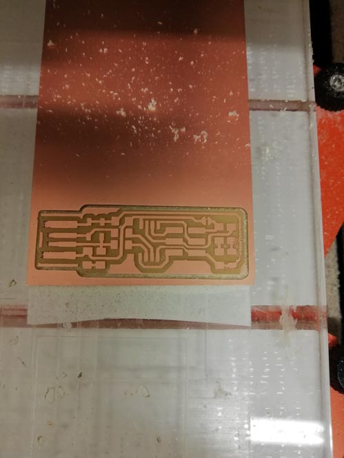
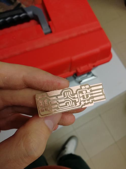
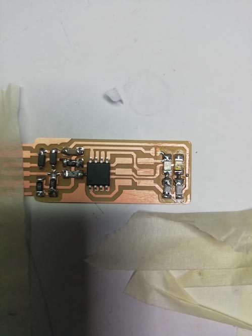
As you can see there is some extra copper, before stuffing I cut it out. I used sandpaper to make the surface smoother and then washed the PCB with soap.
Soldering
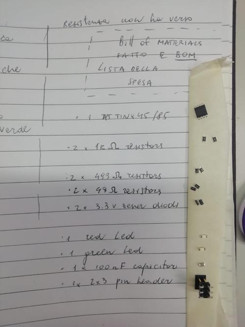
BOMThe bill of materials used for the PCB.
- 1x ATtiny45 or ATtiny85
- 2x 1kΩ resistors
- 2x 499Ω resistors
- 2x 49Ω resistors
- 2x 3.3v zener diodes
- 1x red LED
- 1x green LED
- 1x 100nF capacitor
- 1x 2x3 pin header
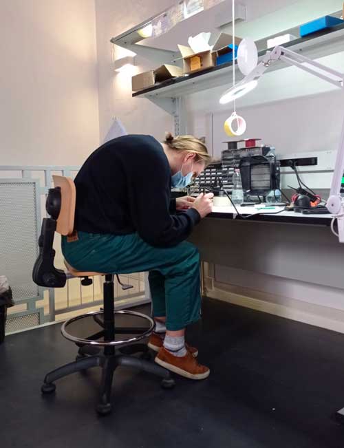
I am not that good at aligning apparently
It's also quite clear that this chair is too high for me or I am too big for this chair lol
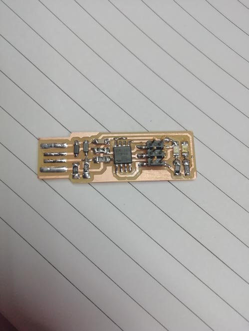
Soldering I made some mess putting too much solder on the resistors' area, but it works
Checking my work and Programming
First with my instructor we checked if visually everything was fine and it was ok. Then with the multimeter setting it up to continuity function we checked if GND and Vcc were having contact. it would be a sign of short circuit, it was fine, too.
My PCB was ready for programming.The software was already installed on the FabLab's computer, since it's not the assignment of this week, we used that. I insterted it using the slow usb port and When i saw the red led on, it was a good sign and the PCB was not getting too hot.
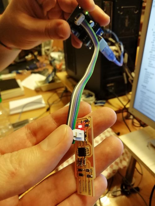
Then I saw on the screen after all the command lines initialized that the computer recognised the PCB
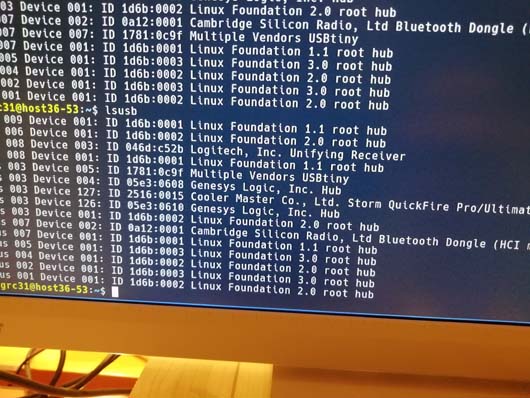
I checked it also on my computer
**UPDATE**
Programming
If you have a MacOS the easiest way to install all the sofware needed is through homebrew. Also because CrossPack is heavy af (12GB). On command line just run:
$ xcode-select --install
Then, run the following to install the latest version of avr-gcc:
$ brew tap osx-cross/avr
$ brew install avr-gcc
As I was building FabTinyISP, I kept following the tutorial made by Brian downloading firmware source code
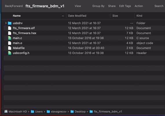
I opened my terminal and entered in the folder that of firmware, once I got there I run make to create .hex file, that is translated .c code into machine binary language.
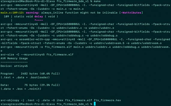
In fact, once this operation completed, the fts_firmware.hex appeared. Woohoo!
Afterwards I downloaded the Makefile written by Neal of my ATtiny45. This time I didn't change anything there because the name "usbtiny" was correct and other features I just left as they were.
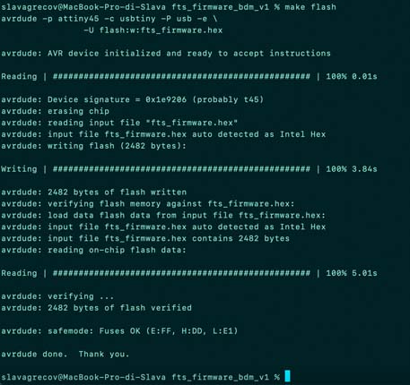
Then I plugged my board into a USB cable and a commercial programmer. I saw my Led turning on, so there was at least connection. Pat attention to the orientation of your ISP header. Either in funcion of the Pin1 or GND plug it in the same manner on both sides using a cable. I run make flash to transmit .hex file onto my board. You'll see some progress bars like this:
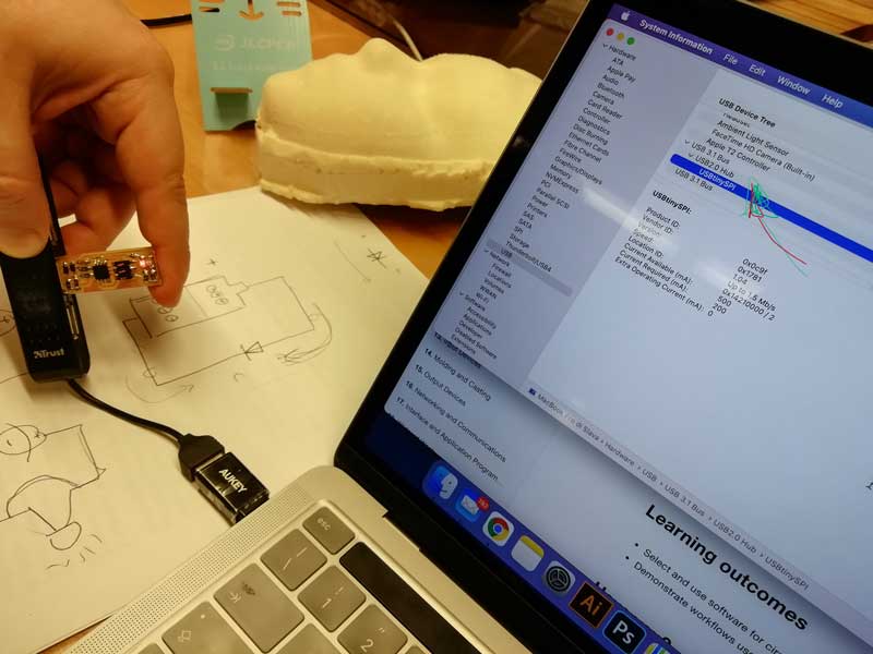
Then I unplugged everything to test if my reprogrammed programmer worked. So on MacOS the path is the following:
> Apple Menu > About this Mac > More Information > USB
I saw my usbtiny, thus it worked nicely.
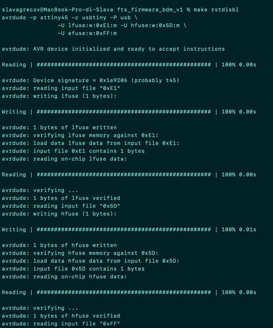
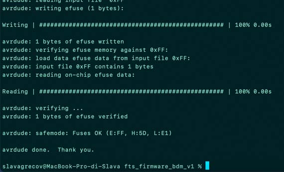
Now it's the time to reprogram our board in a manner that it won't be possible anymore to reprogram it again. Connect the board once more and run make rstdisbl .
Something went wrong when I did it:
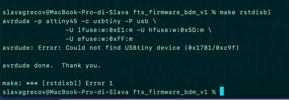
So I found out that my board was not plugged properly and in fact the Led on the programmer was not turned on.
When I debugged it, I run the command again and that was it!