Week 6
Group projectUse the test equipment in your lab to observe the operation of a microcontroller circuit board. You can find our project here
Individual project
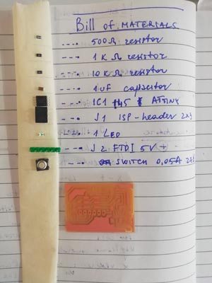
Redraw an echo hello-world board, add (at least) a button and LED (with current-limiting resistor), check the design rules, make it, and test it.
So as to draw the board I used Eagle, I downloaded the library from here and chose to ATtiny45 for this project.
Through Add part I added all the components needed in order to draw this board with extra GND and VCC avoiding counting the exact number one by one.
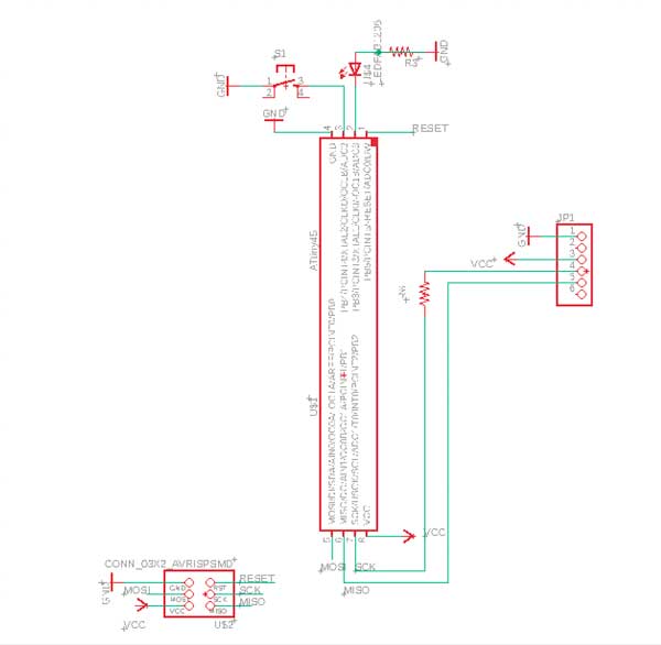
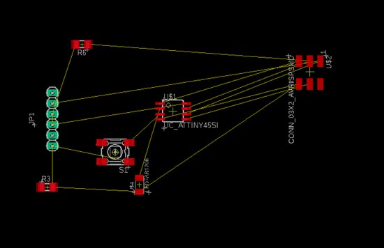
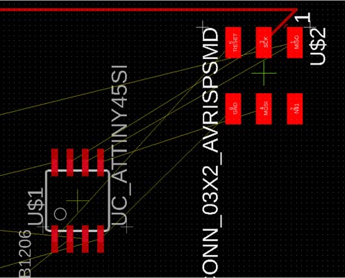
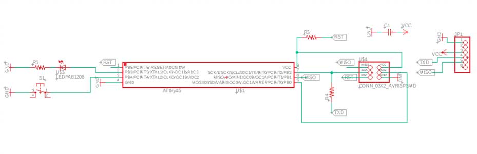
The first schematic looked good, but for some reason vvc of header was not connected to anything on the board.
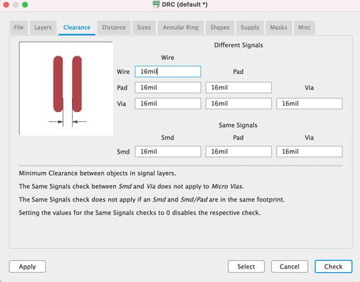
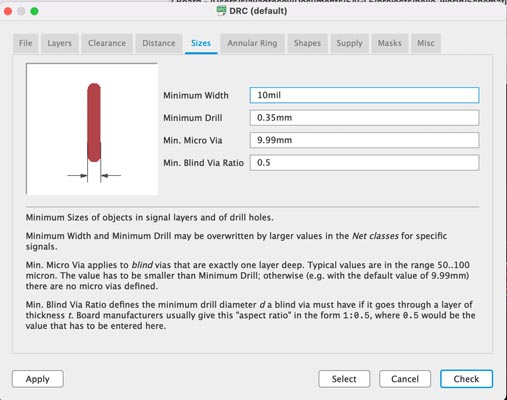
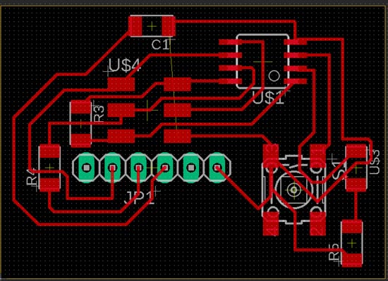
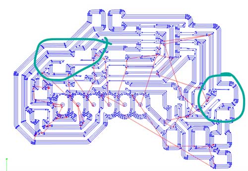
Switching to the board, I set the design rules, that is Clearance to 16 and Sizes to 10, but it turned out to be a bit extreme. That's why I would advise to increase these numbers
These are the problems that I found with the first schematic, with vvc missing on the header
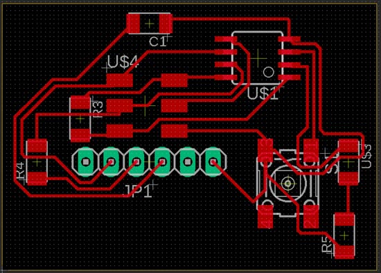
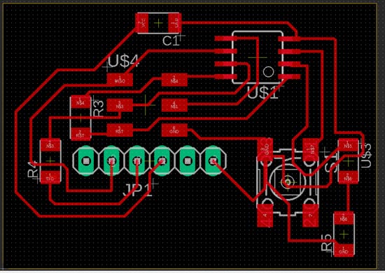
Therefore I drew another schematic
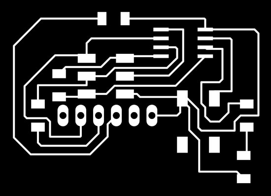
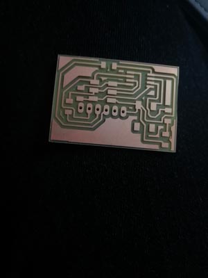
The board I had to adjust many times, since I had had a problem with milling, as cited before clearance parametre was too low. Here some examples with the last final version of board
Mods
I have not noticed these problems on mods, so that created problems while milling. Basically, it just did not mill those traces, but merge them.
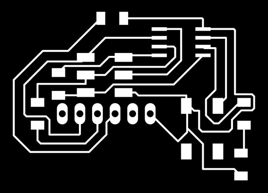
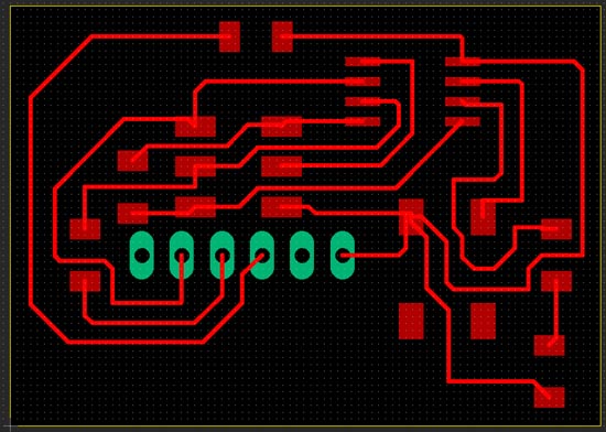
This is the final version of png used for milling
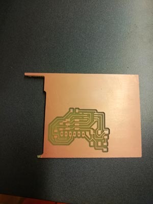
Milling
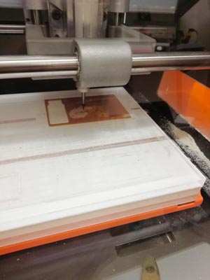
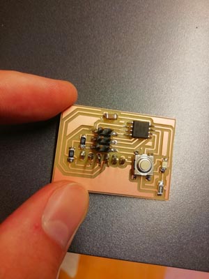
As mentioned before, I milled with an error in my drawing. First, I thought it was a problem with the machine, so I run it twice, but nope. It taught me that I should be more attentive when checking mods, even though all those arrows don't look very clear. This is the result:
Soldering & Test
I didn't have any problems with soldering, but I did have some with test. In fact, I need to debug my PCB, because it didn't work when programming with our instructor. Moreover, I had to fold a bit the header because otherwise it wouldn't have been possible to connect to the wire of computer.
I successfully completed my debug: there was too little solder on pin 8 of AtTiny45, so added it a bit and managed to programm my board making blink the Led.