Week 7
Group project- compare the performance and development workflows for other architectures
You can find our project here
Individual assignment
- read a microcontroller data sheet
- program your board to do something, with as many different programming languages and programming environments as possible
Understanding microcontroller
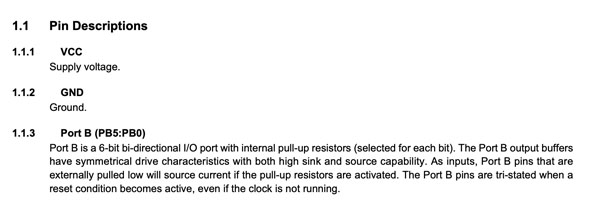
AVR microcontrollers are self-contained tiny computers on a chip with limited flash memory, RAM and CPU just as other computers.
Simply said they work by reading voltages from different pins or by setting up specific output voltages to them.
All pins have a name and secondary functions describes as mnemonics in parenthesis. You can find detailed description in the datasheet of your microcontroller.
The pins are grouped into banks of eight pins, for example B, C or D, the pins accordingly are PB0,PB1,PB2 etc.
Also the reference to these banks of eight pins is to be done by eight-bit binary numbers in order to "turn on" or "off" a specific pin.
It's important to outline that in case the voltage on the pin is greater than of the supply the bit is set to one. When it is lower it is read as zero.
Toolchain
To create the architecture AVR it is necessary to have a chain of tools, that is called toolchain :- a text editor
- a compiler
- programmer: an uploader software on computer like AVRdude and a hardware flash programmer (that you've done during the week 4 of electronics production)
- Makefile - a text file that groups shortcuts of operations used repeatedly, like serial-port input/output functions
If you have a MacOS the easiest way to install all the sofware needed is through homebrew. On command line just run:
$ xcode-select --install
Then, run the following to install the latest version of avr-gcc:
$ brew tap osx-cross/avr
$ brew install avr-gcc
Et voilà, c'est tout! Well, that's not all, but now you can proceed with CrossPack and Avrdude installed.
During the class with our instructor we learned that there three different registers, that is:
- DDRx that decides the bit direction as input or output
- PORTx as reported below from datasheet Port B is a 6-bit bi-directional I/O port with internal pull-up resistors. The latters are the internal resistors that are activated when needed in order to prevent undesirable effects of the voltage floating state
- PINx this register programs a pin as input. As default all pins are set for input, but there might be the need to check their state and to set them either as outputs or inputs.
Programming
After installing all the necessary software and reprogramming my programmer with the downloaded Makefile for ATtiny45 written by Neal, I changed some lines in the file and saved it as "Makefile".
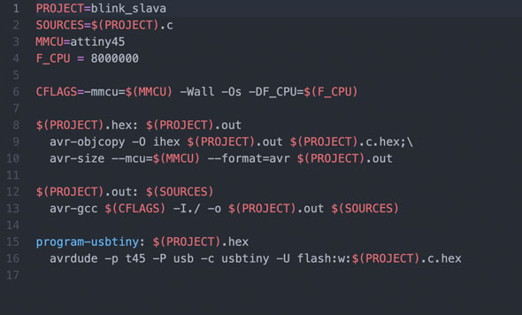
I gave the name to my project that is the same as my code that I'll write in .C later. I also left attiny45 as it's my microcontroller and the F_CPU as it was since we are using standard value of clock. Then I cancelled other unnecessary line leaving just $(PROJECT).hex: $(PROJECT).out and program-usbtiny: $(PROJECT).hex as you can see in the picture above.
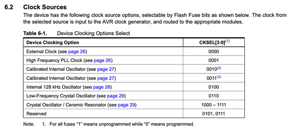
The difference with ATtiny44 that used one of my colleagues is in the settings of Fuses, this command is in charge of the behaviour of our microcontroller and can be of three types:
- Extended
- Low
- High
For ATtiny44 they used low fuses that defines the clock value in funtion of the external or internal source. Whereas the default settings with a value of 8mHZ > 0010 and the microcontroller uses the external 20MHz resonator clock, it was necessary to change the value of fuses to 0111. In case of ATtiny45 instead, we are using the default clock settings using the calibrated internal oscillator.
Then I wrote my first .C code after some tries tempting to capture how it works and most importantly why it didn't work.
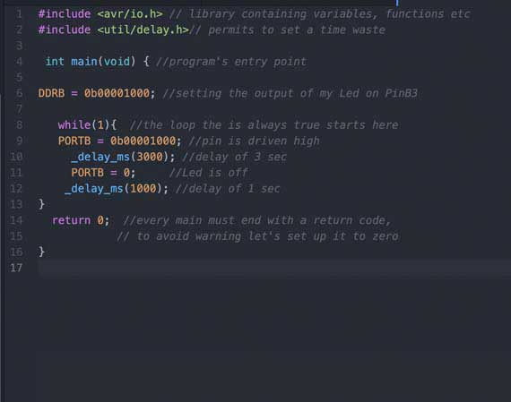
The next step was to go to terminal with cd inside the folder of my makefile and code. I run the command make with which the program translates my (to a certain..certain extent) "human" .c language into machine binary language, hence it creates .hex file and an out file.
Pay attention to what you type, because it is easy to make silly mistakes writing a code in a language that has been unknown till today
Like here
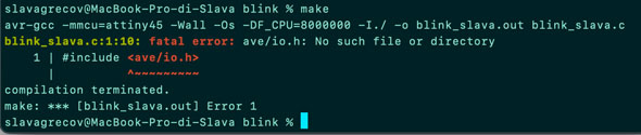
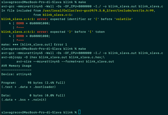
So I corrected it and run it again
So I run the make program usbtiny to flash the .hex file to my chip. I don't know exactly why but make flash didn't work
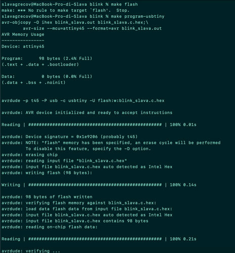
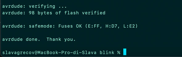
And I did it. Yeah, the great blink blink was happening