Week 9
Individual assignment
- measure something: add a sensor to a microcontroller board that you have designed and read it
For two weeks I would not be at FabLab physically, this is why our instructor gave me Super Starter Kit. Uno R3 Project. I opened the box realising that it will never be so nice packed again.
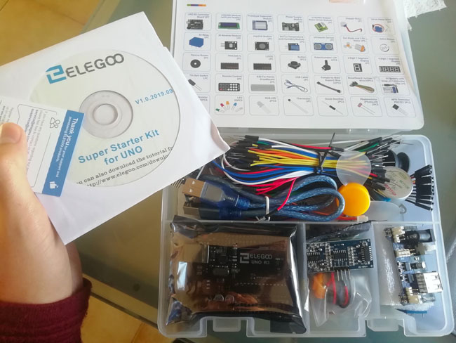
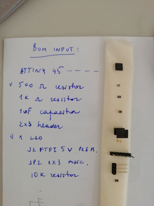
This starter pack contains the following components:
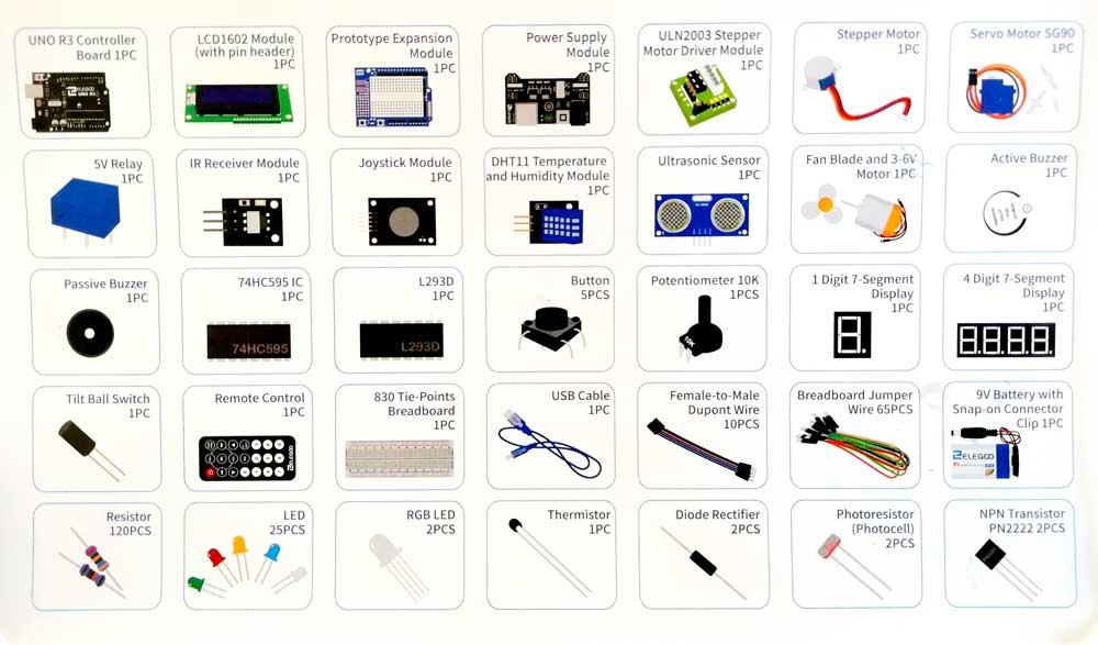
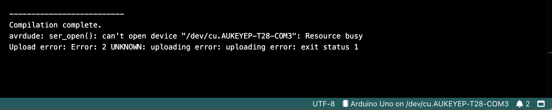
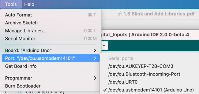
For my project I would mainly need two types of inputs: switch and an infrared motion sensor. For this reason, I tried these inputs on my arduino. Once installed Arduino IDE it is essential to choose the board type and serial port. Normally, the serial port is supposed to be COM and something, a number. In my case, it gave an error. And I chose the one where was specified Arduino. It might be necessary also to install libraries.
Switch
I used the following components:
- (1) x Elegoo Uno R3
- (1) x 830 Tie-points Breadboard
- (1) x 5mm red LED
- (1) x 220 Ω resistor
- (2) x push switches
- (7) x M-M wires
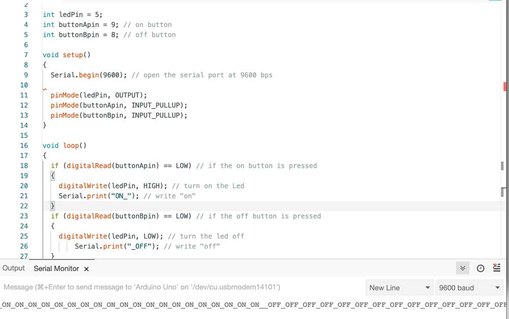
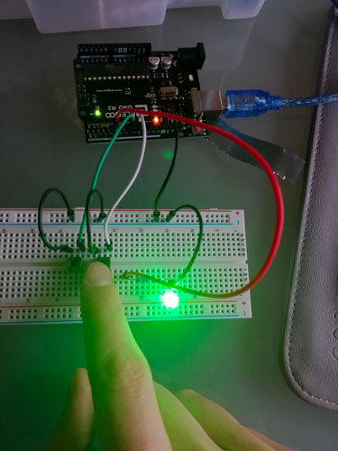
The circuit is pretty simple: it has two switches and an Led. One switch turns the light on, while the second on the left turns it off. In order to see the result also on my screen I made it write on serial monitor "on" and "off" as shown below. The logic here is the same as with pull-up resistor: when the button is not pressed the pull-up resistor sets a default electrical value for the button, so it's HIGH, When the button is pressed it creates a small resistence path to GND and it goes LOW
IR Receiver
The second input that I tried from Arduino kit was IR Receiver that permits to have wireless control of project. As explained in the tutorial to this kit IR detectors are little microchips with a photocell that are tuned to listen to infrared light. It is a invisible light to human eye, but every living object emits it. Normally this type of sensors from Arduino kit are used for remote controllers for TV, for instance. Moreover, IR detectors are specially filtered for IR light, they don't suit for detecting visible light. Inside we can find a demodulator that looks for modulated IR at 38 KHz. The logic is similar to the digital output of switches explained above: either IR receivers detect 38KHz IR signal and output low (0V) or they do not detect any and output high (5V).
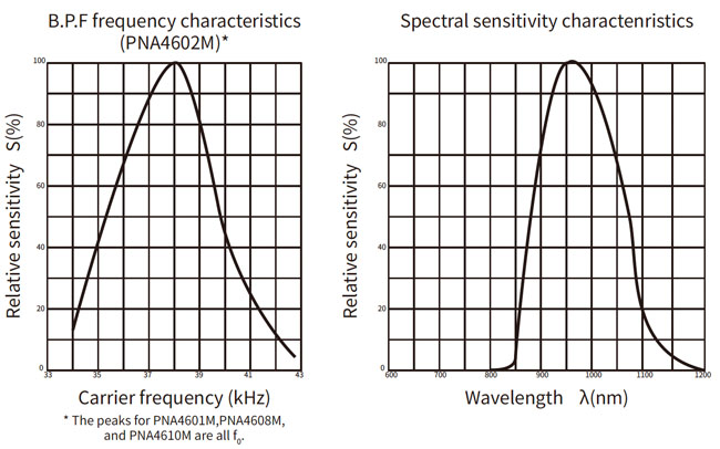
From the datasheet graphs it is possible to notice that the peak frequency detection is at 38 KHz and thepeak LED color is 940 nm. We could use also other values from 35 KHz to 41 KHz range, but the sensitivity will be worse and will not detect as well as at 38 KHz, the same with Led.
I used the following components:- (1) x Elegoo Uno R3
- (1) x IR receiver module
- (1) x IR remote
- (3) x F-M wires
The code is quite complex, I found it in the tutorial introduction to this kit on the official website. There were two versions of the same programm: when you push a button on the remote controller the IR sensor receives the signal and on the serial monitor you can see the button pushed. The first code was more readable for me, so I tried it first even though eventually it didn't work.
#include "IRremote.h"
#include "IR.h"

IRrecv irrecv(RECEIVER);     // create instance of 'irrecv'
decode_results results;      // create instance of 'decode_results'

void setup() {
  Serial.begin(9600);
  Serial.println("IR Receiver Button Decode");
  irrecv.enableIRIn();
}

void loop()
{
      switch(results.value)
       {
  case 0xFFA25D: Serial.println("POWER"); break;
  case 0xFFE21D: Serial.println("FUNC/STOP"); break;
  case 0xFF629D: Serial.println("VOL+"); break;
  case 0xFF22DD: Serial.println("FAST BACK");    break;
  case 0xFF02FD: Serial.println("PAUSE");    break;
  case 0xFFC23D: Serial.println("FAST FORWARD");   break;
  case 0xFFE01F: Serial.println("DOWN");    break;
  case 0xFFA857: Serial.println("VOL-");    break;
  case 0xFF906F: Serial.println("UP");    break;
  case 0xFF9867: Serial.println("EQ");    break;
  case 0xFFB04F: Serial.println("ST/REPT");    break;
  case 0xFF6897: Serial.println("0");    break;
  case 0xFF30CF: Serial.println("1");    break;
  case 0xFF18E7: Serial.println("2");    break;
  case 0xFF7A85: Serial.println("3");    break;
  case 0xFF10EF: Serial.println("4");    break;
  case 0xFF38C7: Serial.println("5");    break;
  case 0xFF5AA5: Serial.println("6");    break;
  case 0xFF42BD: Serial.println("7");    break;
  case 0xFF4AB5: Serial.println("8");    break;
  case 0xFF52AD: Serial.println("9");    break;
  case 0xFFFFFFFF: Serial.println(" REPEAT");break;
  default:
     Serial.println(" other button   ");break;

}
}
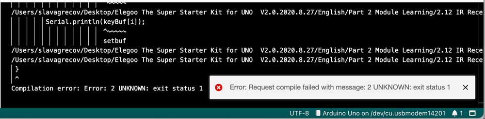
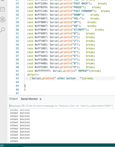
I noticed it had several errors, I kept seeing this message below, then I figured out there was a problems with parenthesis.
switch..case functions in a similar way to IF statements and permits to add specific code that will be executed once the conditions are satisfied. In fact, a switch statement compares the value of a variable to the values specified in case statements. In the moment when a case statement is found whose value matches that of the variable, the code in that case statement is run. break allows to exit the switch statement. Otherwise the latter will go on executing the following expressions until a break or the end of switch statement.
Exactly this happened also in my case. That's why I added a break in the last line in the code above, but anyway it kept running and showing only "other button" like in the picture below.
Then I used the second code, more difficult to understand, but at least it did work! Basically, all the various definitions, like case in the first version, are taken from the library, in particular Ir.h file
#include "IRremote.h"
#include "IR.h"

IRrecv irrecv(RECEIVER);     // create instance of 'irrecv'
decode_results results;      // create instance of 'decode_results'

void setup() {
  Serial.begin(9600); // use serial port at 9600 bit/s speed
  Serial.println("IR Receiver Button Decode");
  irrecv.enableIRIn();
}

void loop()
{
  int tmpValue;
  if (irrecv.decode(&results)) // have we received an IR signal?
  {
    for (int i = 0; i < 23; i++) // for 23 possible options e.g buttons
    {
      if ((keyValue[i] == results.value) && (i− <KEY_NUM)) // if value corresponds to one specified in the array
      {
        Serial.println(keyBuf[i]); // print this value
        tmpValue = results.value;
      }
      else if(REPEAT==i)
      {
        results.value = tmpValue;
      }
    }
    irrecv.resume(); // receive the next value
  }

  }
I also tried to calculate the approximate functioning distance of the remote and IR sensor, it was 2 metres circa.
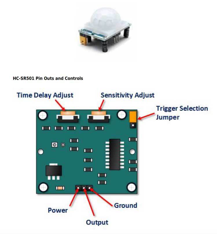
Passive IR Motion sensor
Finally, for my PCB I would like to use HC-SR501 Passive Infrared (PIR) Motion Sensor as it allows to detect living objects, that is a part of my final project. As specified in datasheet the module features adjustable sensitivity that allows for a motion detection range from 3 meters to 7 meters, plus time delay adjustments and trigger selection that allow for fine tuning within application.
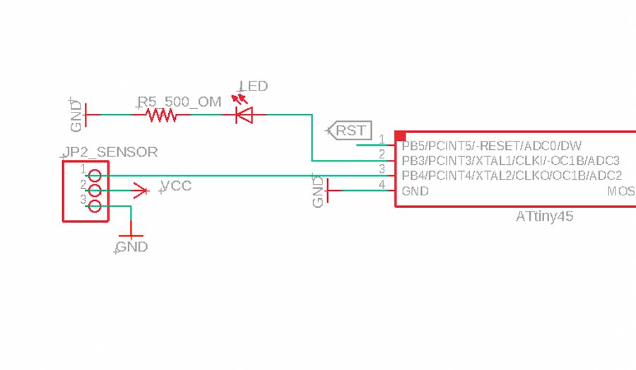
Since the input voltage is 5V and the output is 3.3V I tried to construct a voltage divider as explained on sparkfun. The sensor uses three pins, this is why in Eagle library I found SPDTswitch that permits to connect them. I have serious doubts that my solution works, but whilst on one side I connected the resistor to GND, on the other side of Vout I connected it to the Led's resistor, as you can see below.
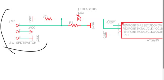
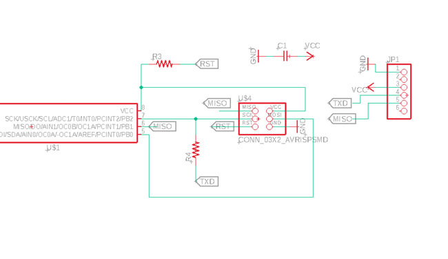
Afterwards I found out that there was no need of a voltage divider as ATTiny45 interprets 3.3V as HIGH, so I just connected the output pin of the sensor to a pin of microcontroller. Then I prepared the png files for milling.
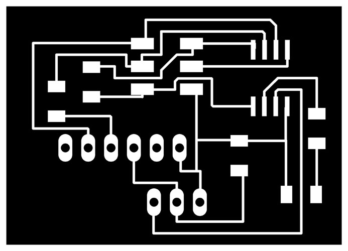


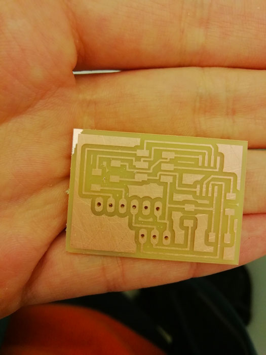
So I continued with milling and soldering the PCB.
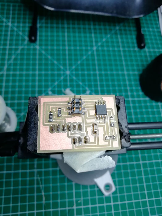
PIR in action
I managed to programm my PCB and it worked, but the actual use of PIR sensor and code for it, I studied and implemented in my final project that you can explore on this page.
Docs
Download the files from here