9. Embedded programming
This week I will try to program my two board to do several stuff. I’ll use C language for one board and the arduino coding the is based on C++ for the other.
Programing ATtiny 44.
Fist I have gone through the data sheet of ATtiny to understand the pinout of it.
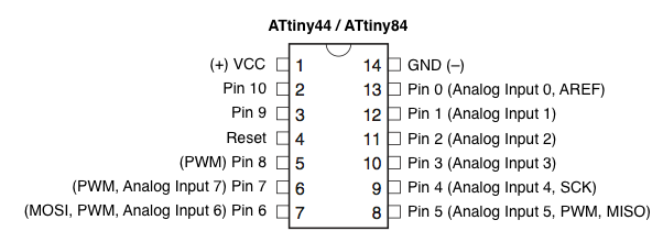
As we can see from the Pins configuration of the board, the attiny44 has a VCC PIN and GND pin for powering, Also it has inputs and outputs pins ports A and ports B with an internal pull-up resistor, the operating voltage for attiny44 is between 1.8V to 5.5V.
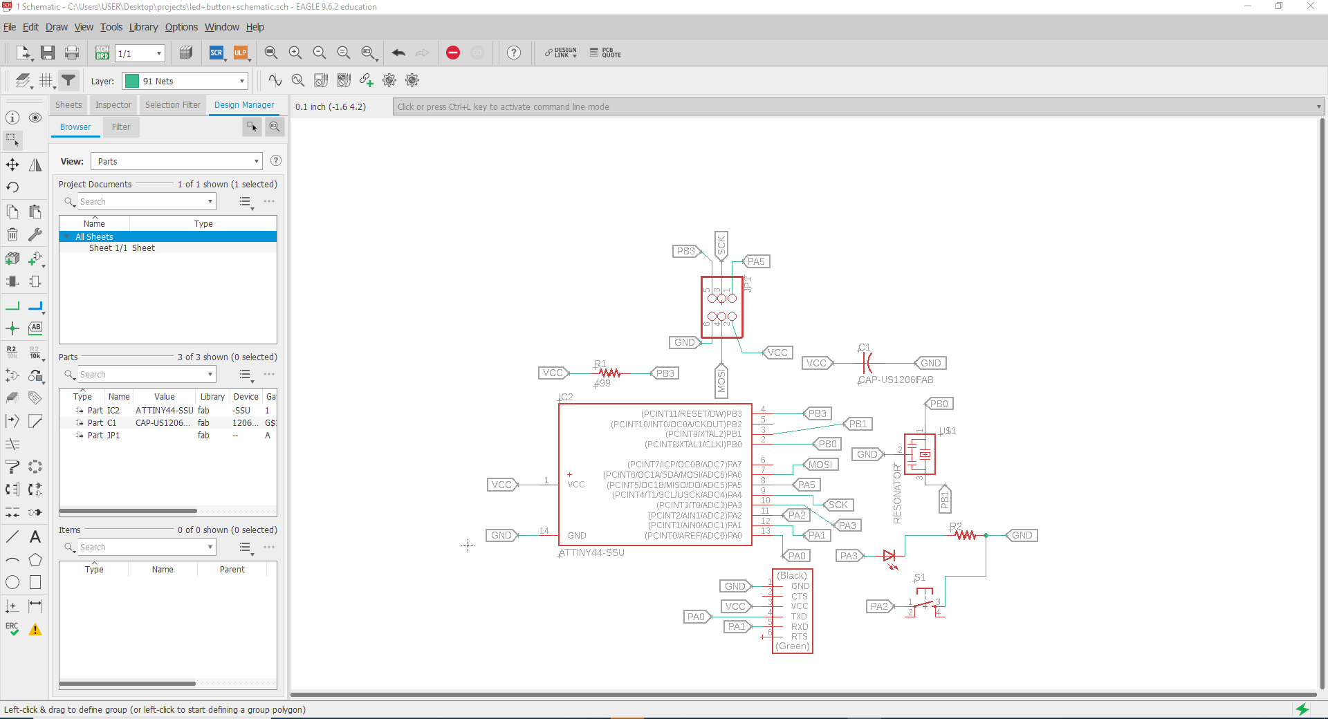
So I used my programmer that I made in week 5 to upload the code to my board I have designed, and following the same steps previously, I programmed my Attiny so that when I click the push button the LED will turn on , the LED is attached to pin PA3 while the push-button is attached to pin PA2.
to program the board using C language there are three important register I needed to learn about:
The Data Direction Register(DDRx) which determines whether the pin is set as Input or Output, as default all pins are inputs and to set it as Output we set 1 in the Data Direction Register (DDR)
For example:
so let say we would like to assign the port B5 in the Atmega328 as an output: DDRB = 0b00100000
The port output register(PORTx) which tells whether the port is HIGH OR LOW when it is used as an Output
The port input register(PINx) used to read the input value
to read more about it you may refer to the link
Once I understood the data registry I started my coding for LED to turn on once i click the button.
I used arduino IDE to run my code.
#include <avr/io.h>

int main(void) {
DDRA |= (1<<PA3);
DDRA &= ~(1<<PA2);
PORTA |= (1<<PA2);
while(1)
      {
if(PINA &(1<<PA2))
{
PORTA &=~ (1<<PA3);
}
else
{
PORTA |= (1<<PA3);
      }
      }
}
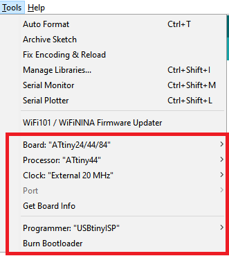
to use the board you have to burn the Bootloader by going to Tools>Burn Bootloader, it is done only one time,
then selecting the following settings:
Attiny 44 as the main board from the tools tab,
Processor>Attiny44,
Clock>External 20MHz
Programmer>USBtinyISP
Sketch>Upload
programming Atmega328 with Arduido IDE.
I wanted to program my rgb to change color. so first I checked my board pins numbers.
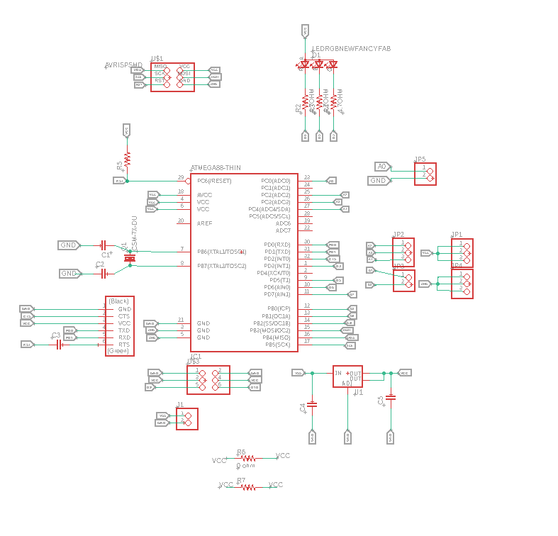
As we can see from the schematic diagram that the RGB is attached to the pins PD3,PD5 and PD6, which correspond to D3, D5, D6 pins on the schematic diagram ofarduino uno, you can figure that from Atmega328p arduino uno pinout diagram.
then I started programming my board using the ftdi cable after the bootloader was burned ( refer to attiny44 step) and with the help of the arduino community tutorial, I managed to light up my built in rgb led using the following code,
the following syntax are used:
int red_pin= 9; assigning variable used for RGB red light pin which is wired to pin 9.
int green_pin = 10; assigning variable used for RGB green light pin which is wired to pin 10.
int blue_pin = 11; assigning variable used for RGB blue light pin which is wired to pin 11.
pinMode(red_pin, OUTPUT); syntax is used to configure the red light pin to act as an OUTPUT.
RGB_color(255, 0, 0); calling for a RGB color function
void RGB_color( , , ) declaring a function named RGB_color
analogWrite( , ); to write an analog value to a certain pin.
int red_pin= 9;
int green_pin = 10;
int blue_pin = 11;
void setup() {
  pinMode(red_pin, OUTPUT);
  pinMode(green_pin, OUTPUT);
  pinMode(blue_pin, OUTPUT);
}
void loop() {
  RGB_color(0, 255, 0); // Green
  delay(2000);
    RGB_color(255, 0, 0); // Red
  delay(2000);
  RGB_color(0, 0, 255); // Blue
  delay(2000);
  RGB_color(255, 255, 125); // Raspberry
  delay(2000);
  RGB_color(0, 255, 255); // Cyan
  delay(2000);
  RGB_color(255, 0, 255); // Magenta
  delay(2000);
  RGB_color(255, 255, 0); // Yellow
  delay(2000);
  RGB_color(255, 255, 255); // White
  delay(2000);
}
void RGB_color(int_red_value, int_green_value, int_blue_value)
 {
  analogWrite(red_pin, red_value);
  analogWrite(green_pin, green_value);
  analogWrite(blue_pin, blue_value);
Group Assignment.
Aduino IDE
Arduino IDE Arduino is a very popular and most commonly used open-source electronics platform based on easy-to-use software and Hardware. Arduino is fundamentally a C/C++ programing environment. It operates a coding language called Wiring which is simple, which makes it easy to write coding scripts to send to the microcontroller to perform tasks. These scripts are called Sketches by Arduino. Usually shields come with already written sketches that can be loaded in to the app, compiled and downloaded to the base board.

Advantages:
Cross-platform - runs on Windows, Macintosh OSX, and Linux operating systems. Most microcontroller systems are limited to Windows.
Easy to learn with a lot of online resources to learn
Huge supporting community.
Simple and easy programming environment - thaT IS easy-to-use for beginners and all other levels , yet its flexible enough for advanced users to test their maximum abilities.
Open source and extensible software - The Arduino software is published as an open source tool, available to be extensioned by experienced programmers. The language can be expanded through C++ libraries, and people wanting to understand the technical details can make the leap from Arduino to the AVR C programming language on which it’s based. Similarly, you can add AVR-C code directly into your Arduino programs if you want to.
Disadvantages:
No understanding of the AVR microcontroller.
shields and Sketches can be considered difficult to modify.
No debugger included for checking scripts. When errors arise, some do not have a clear statement of where or why this error message is showing, it won’t direct you or give solution unless you have experience with Arduino.
For using with Attiny. Attiny 44 in our case, we need to install the package, it is also required to burn the Arduino bootloader onto the chip to make sure the chip will accept any programs uploaded via the Arduino IDE.
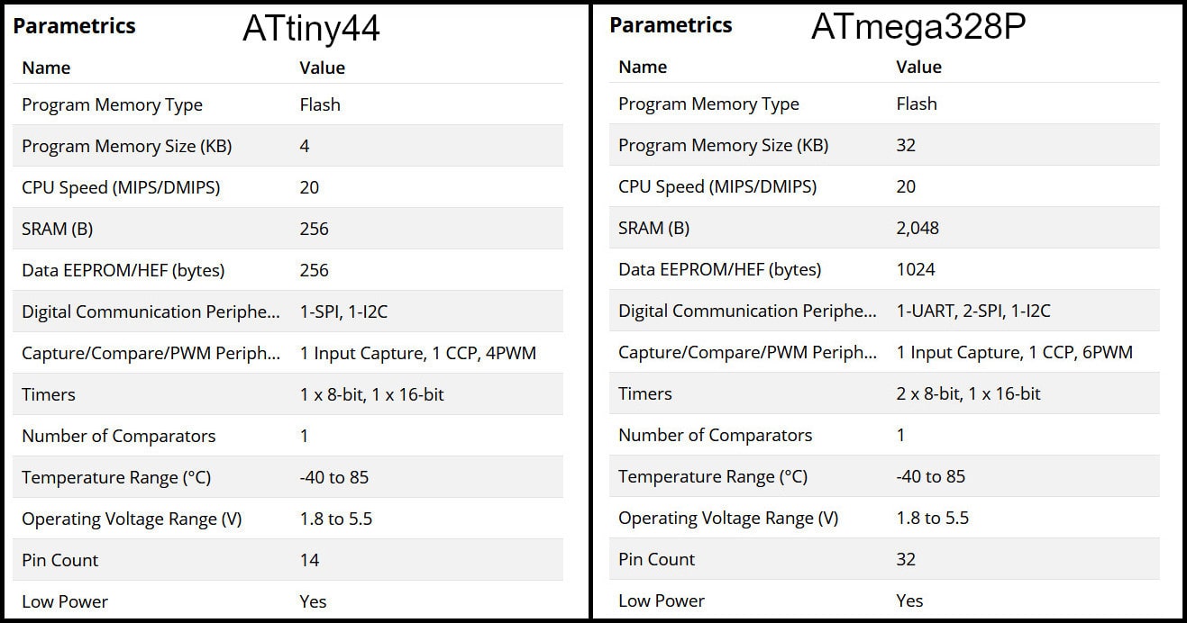
Attiny44 VS Atmega328:
in the table below you can find the comparision between both micro controllers. “tinyAVR microcontrollers (MCUs) are optimized for applications that require performance, power efficiency and ease of use in a small package”, where “megaAVR microcontrollers (MCUs) are the ideal choice for designs that need some extra muscle. For applications requiring large amounts of code.”
So I tried to upload a long code on both controllers to see how they perform. First I upload a code on the Atmega328p and the result on compiling is shown below.
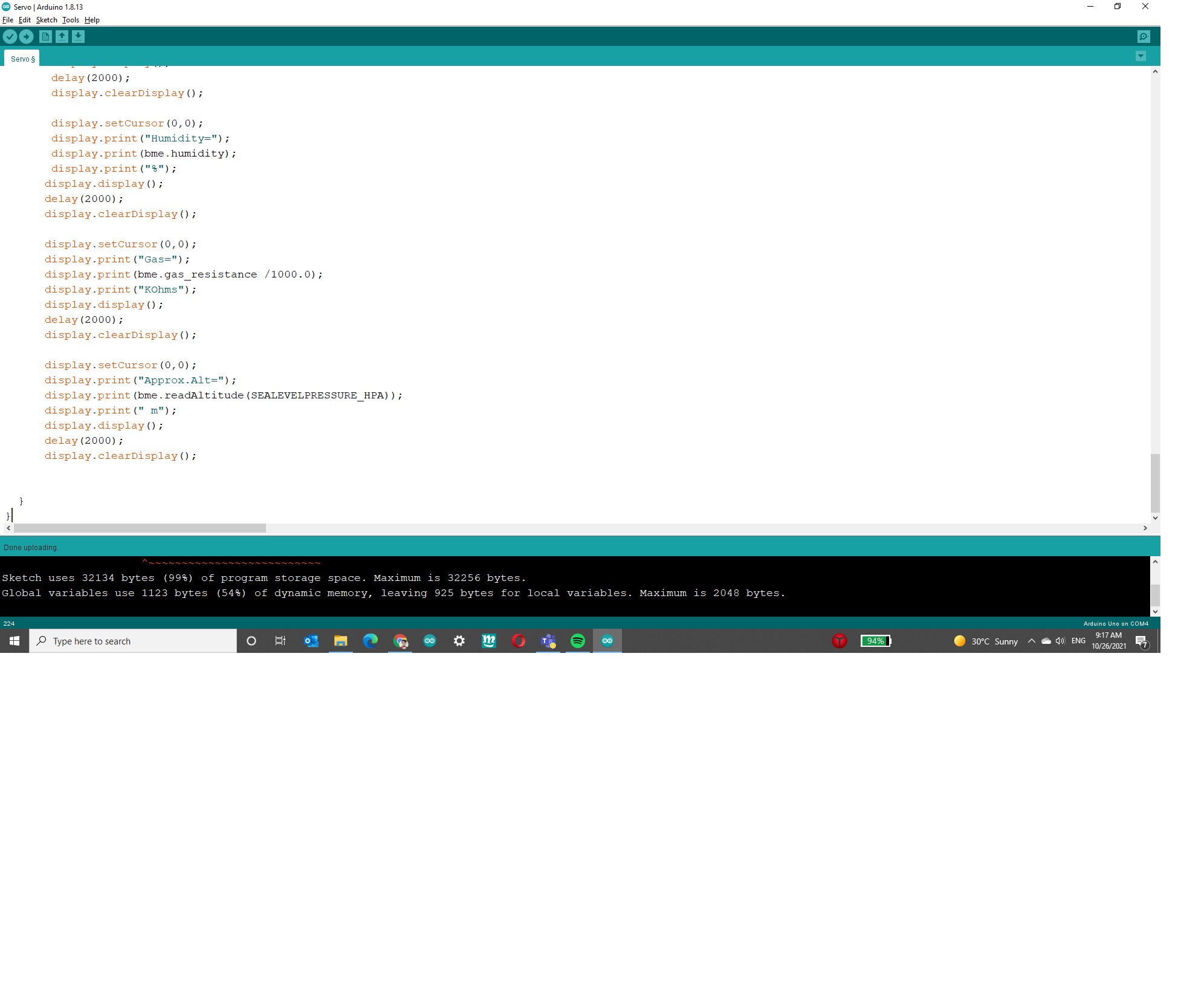
the total size of the long code was 32134 bytes and it took 99% of the total size of the atmega. it took a bit long but it compiled successfully.
the result of uploading a shorter code is shown in the image below.
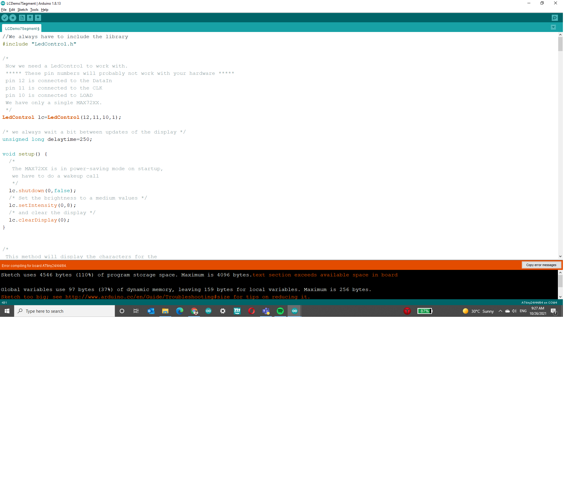
The size of the code was 4546 bytes and it was 110% of the Attiny size so the compiling failed.
References:
[waleed] (https://fabacademy.org/2020/labs/uae/students/waleed-alhamdi/assignments/week09/)