17. Machine design and Mechanical design.
In this week I have to explain my part in the group assignment Mechanical design & Machine Building:
Mohammed Alshamsi and I were in charge of the Z-Axis. for me, I handled the dremel holder and he handled the attachment to the z-axis rod.
design.
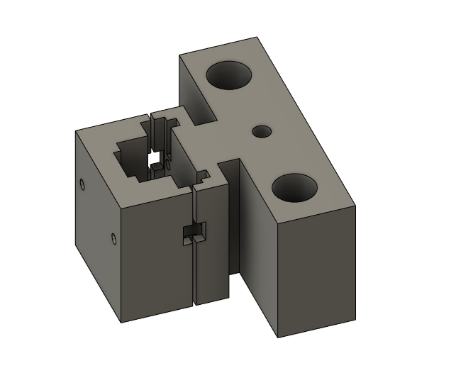
For the z-axis design , we had two main concerns: mechanism of moving along the axis and mechanism of fixing the motor ( spindle) on the axis. The first design had the first motor we tried to use but it failed. we agreed with the y-axis team that the distance between the two holes for the linear rail will be 80 mm, and the lead screw would be in the middle. the design was like this:
The design was made to give space for the spindle motor to fit perfectly then the cover will be screwed to tighten the hold of the motor. but since the motor failed we changed it to a dremel multi tool. We made new design and it’s like this:
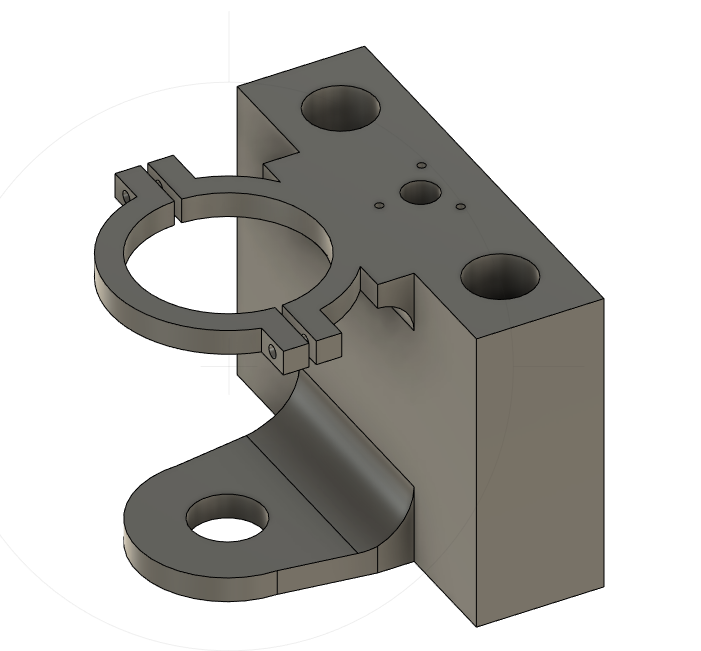
This design was better since it considered the screw holes for the anti back-lash nut. and for the dremel it had two holding points. The lower one is like a rest for the head of the dremel and fits it perfectly to restrain any movement or vibration. The upper part was designed to hold the dremel from the middle and to tighten on it with screws for a better fit. it should be mentioned that the holes design took in consideration the fact the 3d printed material will give a smaller holes that in the design which is opposite for the laser cutting.
Fabrication.
he design for the z-axis spindle holder was printed first by a zortrax printer and it looked like this:
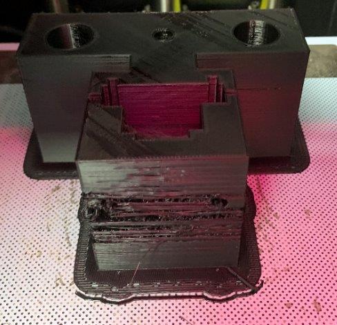
It failed due to the cold room temperature. and since we changed the design for the new motor, we used an ultimaker printer with PLA for the main part and PVA for support. and it looked like this:
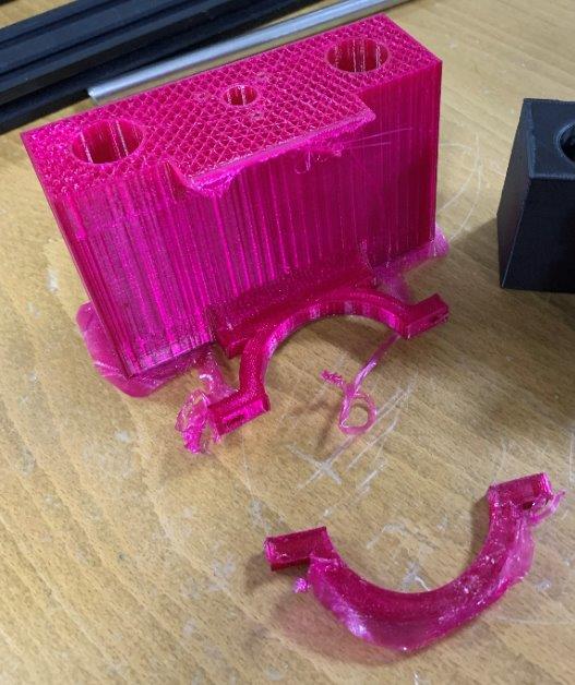
The PVA support was stuck in the nozzle so it ruined the whole printed part. so next print we used PLA as a support from the same nozzle and it worked the result was like this:
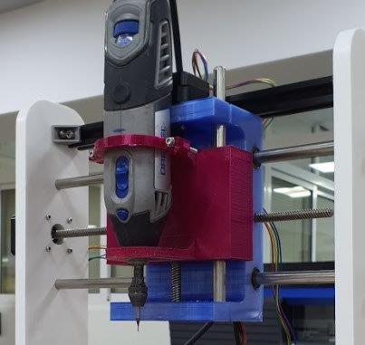
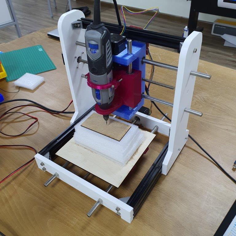
Assembly.
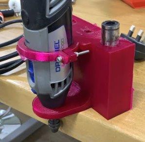
First we added the ball bearing to the holes which are made for the linear rail. they were a tight fit. Then we added the anti back-lash nut then fixed the 3d printed part to the y-axis using the linear rail then added the lead screw which is attached to the z-axis motor. Then eventually we added the dremel spindle and tightened it to the 3d printed holder. the result was like this: