9. Embedded Programming
Assignment definition
Individual assignment
read a microcontroller data sheet program your board to do something, with as many different programming and programming environments as possible
Group assignment
Compare the performance and development workflows for other architectures
Group assignment
We compared different families of microcontrollers on the group assignement page including :
- AVR : I made boards using the AtTiny412 and AVR128DB28
- ARM : I made different boards using the SAMD21 and SAMD11
- Espressif : Maxime made boards using the ESP32
Individual Assignment
I started by reading a datasheet than I decided to try different architectures and microcontrollers. I programmed one using the Arduino IDE in C, one using Python only and a embedded Python interpreter and another one using Arduino ino C.
I also designed a board to test the AVR128DB28 because it seems very interesting to be able to code an acquisition chain embedded in the microcontroller with the 2 op amps it carries.
Reading a datasheet
I had a microcontroller course at university but to be clear it seems that I have forgotten it all. Similarly, I have played with an Arduino in the past but I did not go deep enough to understand how it works inside of it.
This week my objective is to be naive and understand all the electronics gibberish.
Let’s start with the SAMD11C14 and its datasheet.
I wanted to read and build a devkit board for the AVR128DB28 as it integrates ampliops which can be particularily useful for http://ww1.microchip.com/downloads/en/DeviceDoc/AVR128DB28-32-48-64-DataSheet-DS40002247A.pdf First let’s look at the features and block diagram and understand what they mean .
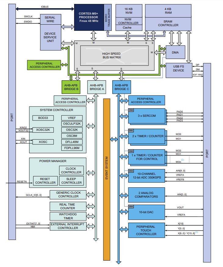
Processor
- ARM Cortex-M0+ CPU running at up to 48MHz : This the type of microprocessor on the microcontroller and its frequency. With this we can know the kind of activity it performs best and at which speed it works.
- Single-cycle hardware multiplier : The whole system uses 1 clock so everything is synchronized.
- Micro Trace Buffer : No idea
Memories
- 16KB in-system self-programmable Flash : the size of the program memory. Flash is also the type of memory in Flash drives aka USB sticks.
- 4KB SRAM Memory : SRAM or Static random-access memory is volatile memory it works if the power is on and as soon as the power is off its wiped off.
EEPROM is a type of memory that is also stable.
System
- Power-on reset (POR) and brown out detection (BOD) : These are protections against unknown state of the microcontroller. POR makes sure the device is reseted when powered on and BOD resets the device when the power supply makes it possible to behave in a non controllable way.
- Internal and external clock options with 48MHz Digital Frequency Locked Loop (DFLL48M) and 48MHz to 96MHz Fractional Digital Phase Locked Loop (FDPLL96M) : Internal clocks provid the rhythm of the device. In a synchronous microcontroller, we need to provide the tempo for each gate to move the signal forward, like in a factory. And similarly to a factory, increasing the frequency increase the speed but can also lead to errors. Lock-loops are used to align the internal clock to the external clock.
- External Interrupt Controller (EIC) : Controller of the pins below
- 8 external interrupts : Used to interrupt the state of the device (start or stop) the device for different reasons. The controller can mask them thus they can be used as a warning instead of a real interruption.
- One non-maskable interrupt : This cannot be masked an is a sort of emergency button.
- Two-pin Serial Wire Debug (SWD) programming, test and debugging interface: See below
Low Power
- Idle and standby sleep modes
- SleepWalking peripherals: This feature allows temporary and asynchronous wake up of a peripheral to perform a task without waking up the CPU from Standby mode. Typically this requires only the clock input with no need for computation.
Peripherals
- 6-channel Direct Memory Access Controller (DMAC): Allows the CPU to perform other work while a data transfer is occurring. This is typically useful in accessing input/output as graphics card, network cards, sound card, disk drive, …
- 6-channel Event System : The Event System lets you connect the on-chip peripherals of an AVR® microcontroller (MCU) without writing any code. This connection enables the peripherals to communicate with each other without involving the Central Processing Unit (CPU) in many AVR devices. So it is similar to the DMAC for peripherals instead of memory.
- Two 16-bit Timer/Counters(TC), configurable as either: Timers count machine cycles, a counter is incremented considering 1 to 0 transition at its corresponding to an external input pin (T0, T1).
- One 16-bit TC with compare/capture channels
- One 8-bit TC with compare/capture channels
- One 32-bit TC with compare/capture channels, by using two TCs
- One 24-bit Timer/Counters for Control (TCC), with extended functions: This is used for creating Pulse width modulation with more control.
- Up to four compare channels with optional complementary output
- Generation of synchronized pulse width modulation (PWM) pattern across port pins
- Deterministic fault protection, fast decay and configurable dead-time between complementary output
- Dithering that increase resolution with up to 5 bit and reduce quantization error
- 32-bit Real Time Counter (RTC) with clock/calendar function : Real-time clocks (RTC) are timers dedicated to maintaining a one-second timebase. In addition, an RTC is often used to keep track of clock time and calendar date either in software or hardware. Many of the features of an RTC are very specialized and required for maintaining high accuracy and very reliable operation.
- Watchdog Timer (WDT) : A watchdog timer (WDT) is a hardware timer that automatically generates a system reset if the main program neglects to periodically service it. It is often used to automatically reset an embedded device that hangs because of a software or hardware fault.
- CRC-32 generator
- One full-speed (12Mbps) Universal Serial Bus (USB) 2.0 interface : Useful to connect with USB
- Embedded device function
- Eight endpoints
- Can run from internal RC oscillator
- Up to three SERCOM, each configurable to operate as either: pre-programmed pins for different communication protocols
- USART with full-duplex and single-wire half-duplex configuration
- I2C Bus up to 3.4MHz
- SMBUS/PMBUS
- SPI
- LIN slave
- 12-bit, 350ksps Analog-to-Digital Converter (ADC) with up to 10 channels: very interesting to convert raw data from a sensor to a digital scale. This is a sort of voltmeter.
- Differential and single-ended input
- 1/2x to 16x programmable gain stage
- Automatic offset and gain error compensation
- Oversampling and decimation in hardware to support 13-, 14-, 15- or 16-bit resolution
- 10-bit, 350ksps Digital-to-Analog Converter (DAC) : Very important to control physical peripherals such as motors or LED at different intensities. This is not a PWM which provides high (5V or 3.3V) or low (0V) output but rather an already nearly smooth output. sps means sample per second and 1 ksps is 1000 sps.
- Two Analog Comparators (AC) with window compare function
- Peripheral Touch Controller (PTC) : The purpose of PTC is to acquire signals to detect touch on capacitive sensors. This could be used to connect and understand the readings from a touchscreen.
- Up to 72-channel capacitive touch and proximity sensing
I/O
Input/Output pins can be programmed to receive a digital signal or write a signal. Some of them can work with analog signal as well.
- Up to 22 programmable I/O pins
Packages
The layout of the device : how are the connections/pins of the devices: through hole, …
https://www.quick-pcba.com/pcb-news/ic-packaging-types.html * 24-pin QFN * 20-pin SOIC * 20-ball WLCSP * 14-pin SOIC
Operating Voltage
- 1.62V – 3.63V
In-depth description
A power-on reset (PoR) generator is a microcontroller or microprocessor peripheral that generates a reset signal when power is applied to the device. It ensures that the device starts operating in a known state.
A “brown out” of a microcontroller is a partial and temporary reduction in the power supply voltage below the level required for reliable operation. Many microcontrollers have a protection circuit which detects when the supply voltage goes below this level and puts the device into a reset state to ensure proper startup when power returns. This action is called a “Brown Out Reset” or BOR
External Interrupt Controller (EIC) The External Interrupt Controller (EIC) helps to configure the external pins as interrupt lines. The external pins can be used as asynchronous interrupts to wake up the device from sleep modes where all clocks have been disabled or to generate event pulses that are connected to the event system.
A frequency-lock, or frequency-locked loop (FLL), is an electronic control system that generates a signal that is locked to the frequency of an input or “reference” signal.
A phase-locked loop or phase lock loop (PLL) is a control system that generates an output signal whose phase is related to the phase of an input signal. There are several different types; the simplest is an electronic circuit consisting of a variable frequency oscillator and a phase detector in a feedback loop. The oscillator generates a periodic signal, and the phase detector compares the phase of that signal with the phase of the input periodic signal, adjusting the oscillator to keep the phases matched.
Serial Wire Debug (SWD) is an alternative 2-pin electrical interface that uses the same protocol. It uses the existing GND connection. SWD uses an ARM CPU standard bi-directional wire protocol, defined in the ARM Debug Interface v5.[20] This enables the debugger to become another AMBA bus master for access to system memory and peripheral or debug registers. Data rate is up to 4 MB/s at 50 MHz. SWD also has built-in error detection.
USB port
The USB port uses 4 pins: two for power (GND and VCC) and two for data, data + and data -. The data + and data - wires carry the same information but opposite (High is low and low is high)
The reason for having two wires for the data carrying opposite information is that we can subtract them at the other end of the wire and remove all the electromagnetic perturbation that was added to the signal. Because the perturbation is the same on both wires and that they carry opposite voltages, subtracting data - from data + gives us a perturbation free double signal. Dividing that in two and we have a noise free signal transmission.
Programming the chips : In-system development
To load program on microcontrollers, there are different options.
ISP : In-System Programming
The original AVR chips use the ISP protocol. This is no longer a standard so I won’t use that option.
UPDI
UPDI is a modern way to communicate and program a microcontroller which requires only two pins : GND and Data (named UPDI pin) that goes in both directions.
UPDI programming is therefore much simpler.
This requires a programmer that I have buit from Quentin’s page for example.
The programmer of Quentin is a simple USB to serial converter and by connecting two headers, you can make it a UPDI and choose the output voltage.
JTAG
JTAG is a standard for verifying designs and testing circuit boards. A standard solution for programming ARM controllers is to use EDBG with a CMSIS DAP programmer.
Bootloader
Bootloaders are programs to load programs. They are a little code script that tells the controller how to accept code. Typically you “flash” a bootloader on a chip to be able to connect to it using a more advanced type of communication protocol such as USB or define even more advanced functions.
Once the bootloader is there you don’t need the JTAG or UPDI interface to connect to the controller and load programs anymore. A typical solution if the microcontroller has a USB interface, such as the SAMD11C14 or the SAMDis to connect directly through USB.
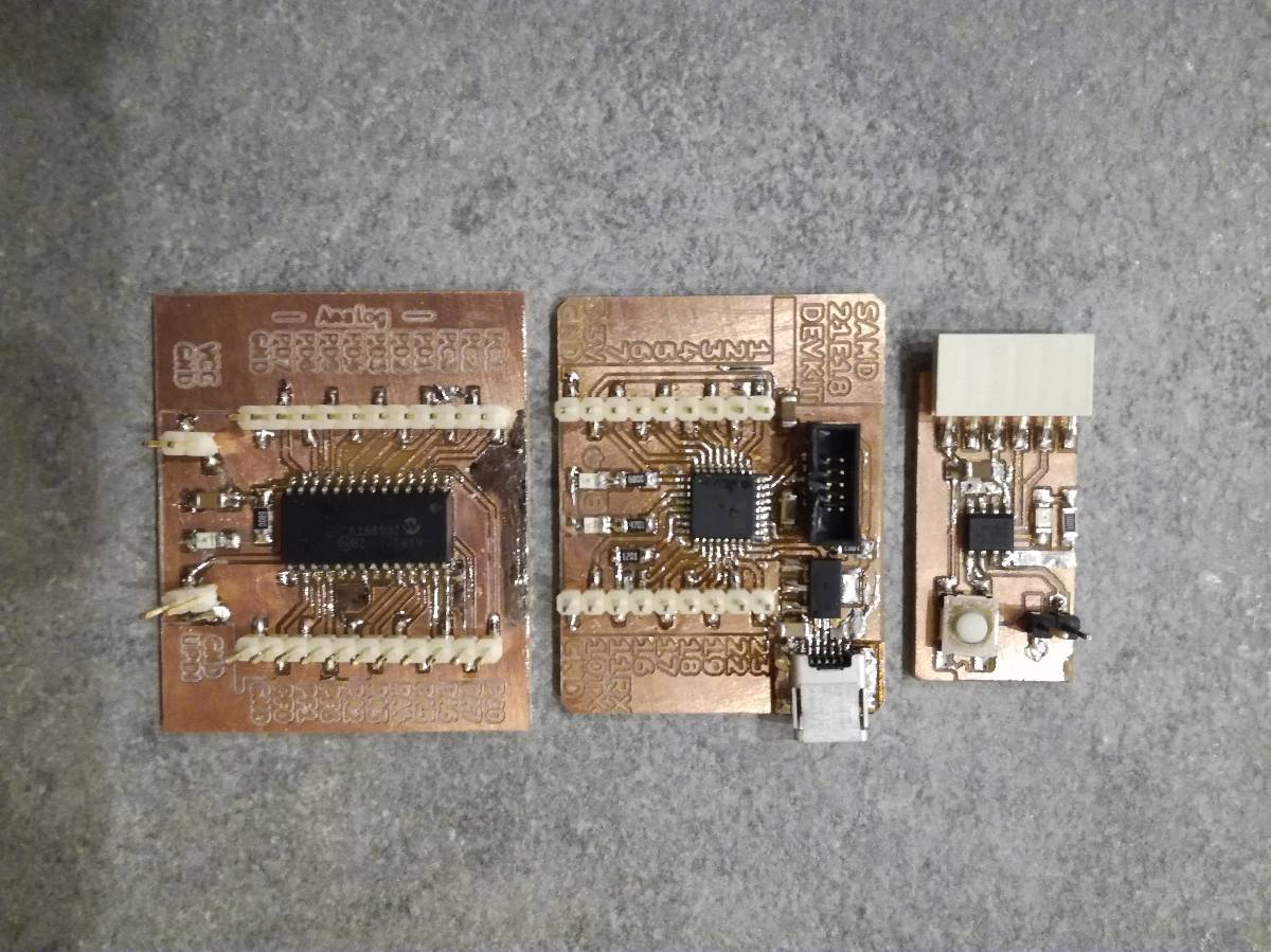
The Boards
I milled and used the following boards :
- SAMD21E18 with Python Interpreter from Quentin’s page : Uploading a .py file directly using CircuitPython for interacting with the board.
- AtTiny412 in C and Arduino
- AVR128DB28 in C
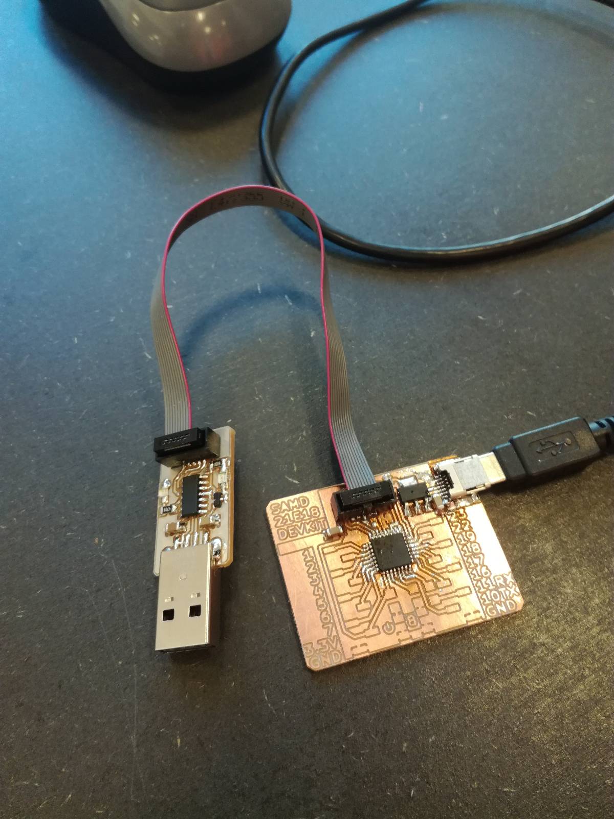
SAMD21E18 with Python Interpreter
For the SAMD21E18, I had to load a bootloader to be able to send data through the USB port.
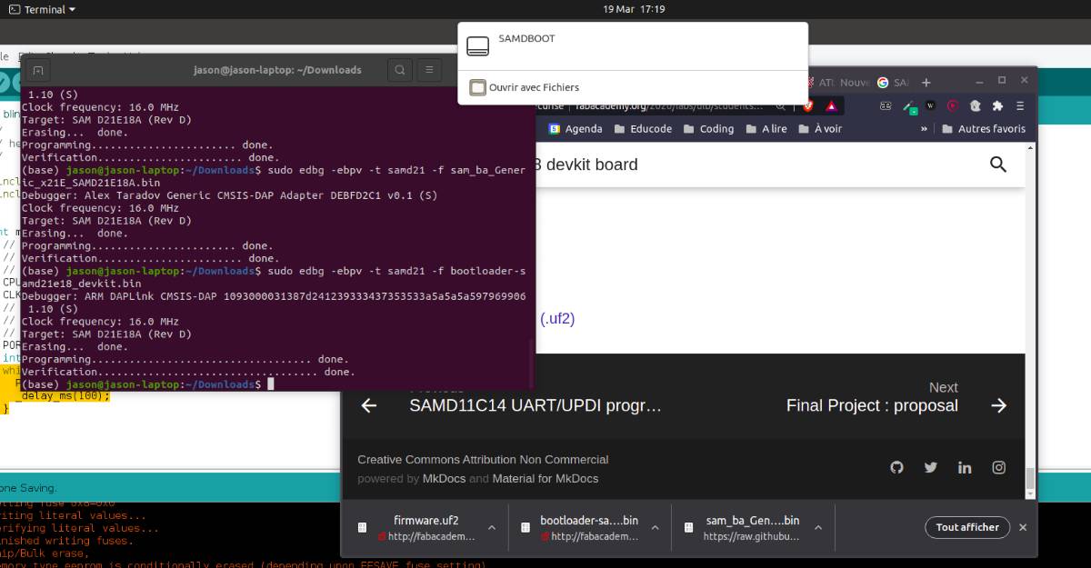
I did that using EDBG and a copy of the Particle.io JTAG programmer of Quentin. I could totally have used my own JTAG programmer which is a copy of Neil’s programmer but I did not have it with me.
EDBG
EDBG stands for Embedded Debugger. edbg is a command line tool developped by Alex Taradov and based on the Formerly Atmel EDBG programmer. It is a CMSIS-DAP programmer.
It works with Atmel-ICE programmer which is expensive but also with custom boards.
It is used to send binary files (bootloaders for example) on a chip through a hardware programmer.
CircuitPython
CircuitPython is a version of python made to fit on a microcontroller. It is designed for embedded programming. Thanks to it, you can just drop your python file on the chip and interact with it using the CircuitPython library.
From adafruit’s page on CircuitPython, we see that it’s only stable for SAMD21 and SAMD51.
I flashed the UF2 (USB Flashing Format) bootloader from https://github.com/ladyada/uf2-samd21 following the explanations of Quentin.
This made the microcontroller available directly as a peripheral memory, so it appears as a USB stick would and you can drop files in it.
Now, two things remain :
- Load CircuitPython on the chip
- Load a python file or use the interpreter
This is even more direct command than another controller, you can communicate without loading any program, directly talking with the python interpreter.
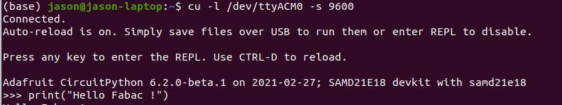
I uploaded the following code to blink the LED but it did not work.
How to upload the code ?
The SAMD21e18 is detected the same way a USB stick would be and to upload your code you just have to drop it into that repository.
By default the code run directly is the one named : code.py
You can also add custom libraries or special libraries for micropython as I did in the Output device week.
import board
import digitalio
import time

led = digitalio.DigitalInOut(board.PA08)
led.direction = digitalio.Direction.OUTPUT

while True:
    led.value = True
    time.sleep(0.5)
    led.value = False
    time.sleep(0.5)
I didn’t understand why working on it, that leg was not touching the track…
I resoldered it and it worked !
AtTiny412
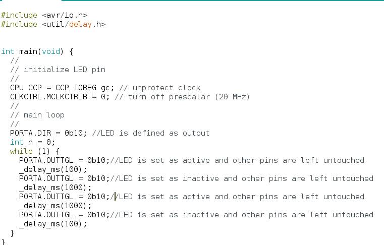
I programmed the AtTiny board after reading the datasheet and going in depth into the registers
To do that, I used the megaTinyCore and the ArduinoIDE.
Reading the datasheet, I read more about registers and how to address them.
I went into depth in the avr.h, the library porting to Arduino IDE.
Loading programs on an AVR chip is in my opinion much easier but more hassle to do at the same time. While using an ARM chip as the SAMD I had to load a bootloader which is one more step and require additional steps before soldering or even adding special connectors on the board. On the other hand, you get a USB connection afterwards so reprogramming is very easy and you directly get a Serial connection included, which is nice for debugging.
With an AVR chip such as the AtTiny412 or the AVR128DB28 here below, you don’t get the USB connection but also you don’t need any bootloader before, and you only need 1 pin to program it.
To program my AtTiny412 circuit, I used Quentin’s UPDI programmer, a SAMD11C based serial converter, taking Serial USB and writing it on the Serial pins.
Quentin’s programmer has an included connector to select the power to provide (5V or 3.3V) and a possibility to short the TX and RX pins through a 4.7k resistor which makes it a UPDI programmer.
I did just that and selected in the Arduino IDE UPDI and as a programmer Serial port and 4.7k (pyupdi style)
AVR128DB28
I designed and soldered the board but did not have time to program it.