5. 3D scanning and Printing
Objectives
- Group assignment: Test the design rules for your 3D printer(s).
- Design and 3D print an object (small, few cm3, limited by printer time) that could not be made subtractively.
- 3D scan an object (and optionally print it).
This week is one of the most creative so I intend to make good use of it in the time that I can allow it.
Introduction
So the main difference with 3D printers compared to more classical methods is that it adds material (additive method) rather than removing some (subtractive methods). It has both pros and cons but additive manufacturing allows to create things that are not possible with subtractive processes. Moreover, you don’t need to care about the complexity of the design itself and how to manufacture it. With 3D printing, it is possible to have access to the interior of a part while building it so we can create imbricated parts and bodies in a single process. Moreover, though the material can be quite expensive, the waste is limited as you don’t remove excess parts (except support).
But it’s not all good with 3D printing. Printers are notoriously known for failing for sometimes unknown reasons, which can be frustrating when doing big parts (and that’s why it’s best to keep it to small parts, one at a time) that take a while (yes, 3D-printing is slow !). Also, the resolution is not as good as subtractive processes as it is limited by the nozzle size and the filament used. It is still good enough however in most cases. Finally, not all materials are available so sometimes you have no other choice than to make a mould or use subtractive processes.
Multiple types of printers exist: filament, resin, and so on… This week I stuck to filament deposition printing but I plan to use resin in the future. We also have an Eden printer (photopolymer jetting technology) at Uni that I used once for a very detailed part but it is extremely expensive so I didn’t use it this week  .
.
Update: working with other printers
After this assignment, I used other printers for various projects. For example, during the wildcard week, I used the Stratasys Eden printer, a very very high resolution printer, to make some microfluidics !
I also used a resin printer (Elegoo Mars 2 pro) to make a very small version of the Atomium, a famous Belgian monument !
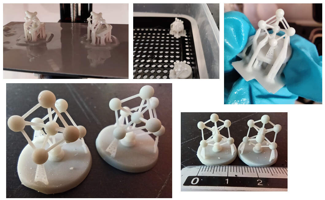
The resin printer is usually higher resolution than FDM. Different methods exist: SLA (i.e. curing the resin using a moving mirror and a UV laser) which provides the highest resolution and a large range of material, SLS which can be very expensive but with a low cost per part, and finally, LCD which is the case of the Mars 2 Pro, which uses a UV LCD screen to cure the resin.
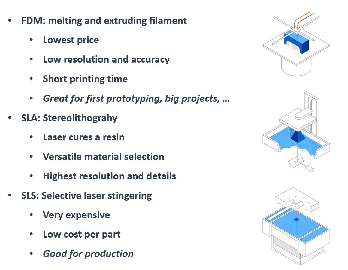
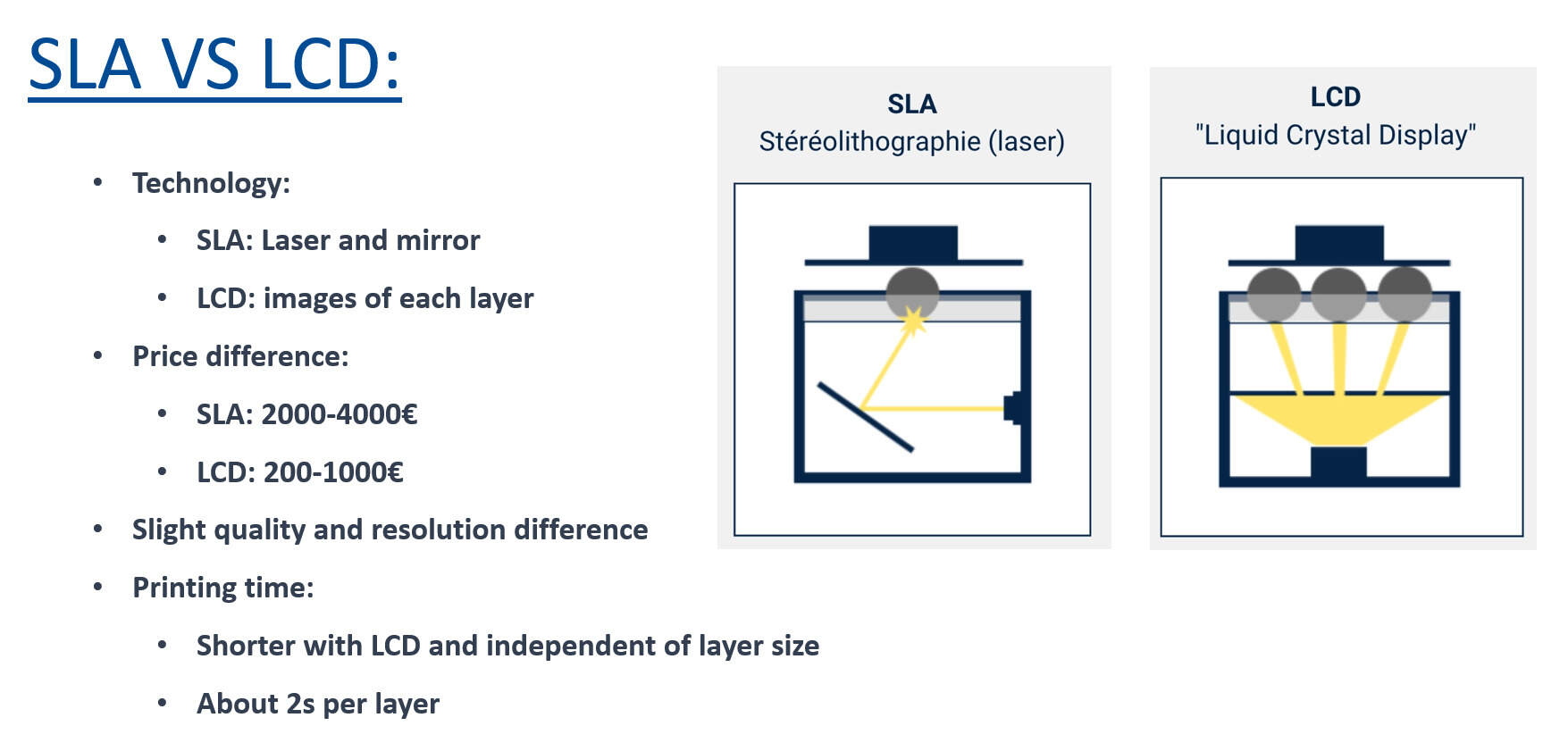
This has the lowest resolution (but still very high) but has the advantage that the printing time only depends on the height of the part, not the surface because it cures a whole slice of the part with a single image, at the same time, no matter the surface of the part itself.
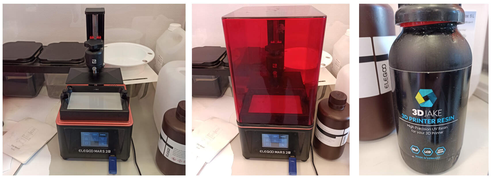
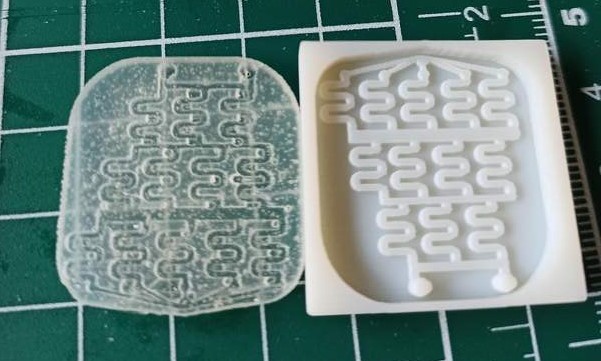
I used the chitubox slicer and post-cured the part with UV light (5 minutes) after removing the support to enhance the mechanical properties.
The power of 3D-printing
Printer characterization and design rules
Some of this documentation is repeated on the group page.
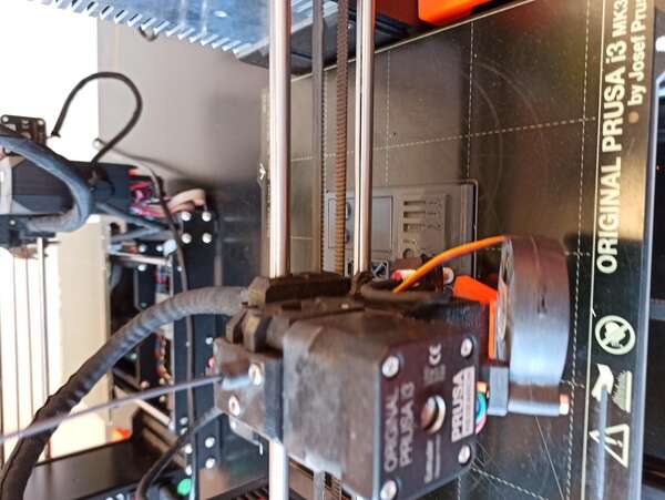
At the lab, we have multiple Prusa I3MK3 and MK3S. With Jason, we started printing multiple test parts, and more specifically, we wanted to get a feel of what the different materials and nozzles change.
Our fablab already printed a simple test part but we wanted to do it ourselves and test out more characteristics of the printer.
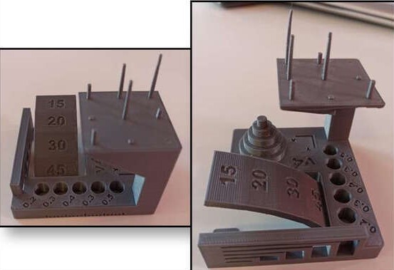
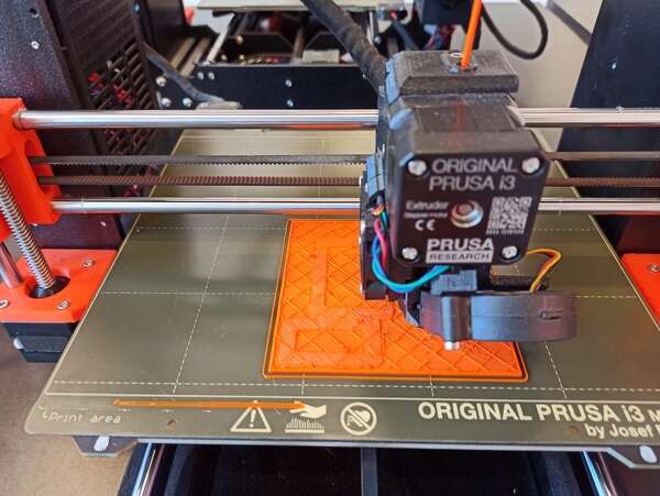
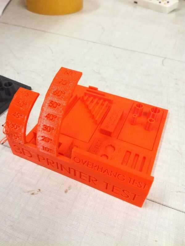
We found another nice test part online that allows us to test gaps, bridges, overhangs, angles, walls and so on. We decided to print this part three times, with no support (otherwise the overhang tests do not make sense).
PLA 0.4mm nozzle
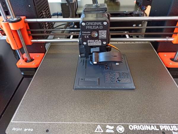
First with a PLA filament and a 0.4mm nozzle (0.2mm resolution), 10% infill. For the PLA, we stuck to the recommended temperature (i.e. 210°C extruder, 60°C heating plate).
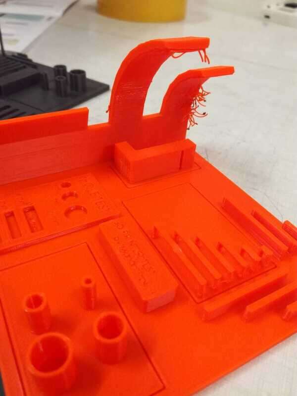
PLA 0.6mm nozzle
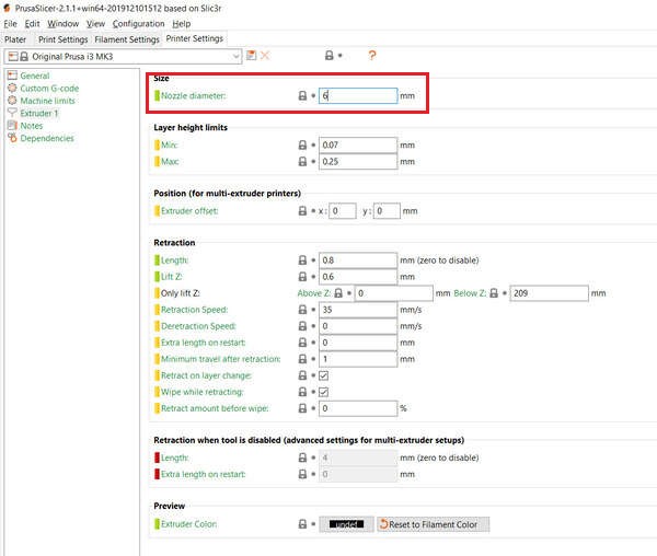
Second, PLA filament, 0.6mm nozzle (0.3mm resolution), 10% infill. Note that you actually need to specify the nozzle diameter in Prusa’s settings.
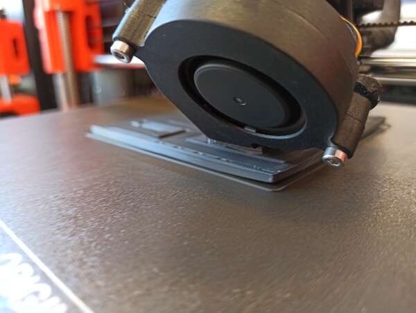
The main difference with a bigger nozzle is the printing time. We went from 4h30 to 3h, a 33% reduction. On the other hand, we lose in resolution and it can especially be seen on the thin walls. We also had trouble with the bottom plate not sticking correctly to the heating plate.
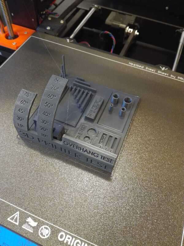
PETG 0.4mm nozzle
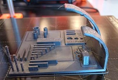
Finally, PETG filament, 0.4mm nozzle (0.2mm resolution.), 10% infill. PETG is PET with added glycol. It is a more rigid but more brittle material than PLA but harder to print (we had worse results than with PLA, especially due to the bottom layer not sticking correctly to the heating plate). It must be heated at a much higher temperature (260°C extruder and 80°C for the heating plate). To help the bottom plate to stick, we added a brim but it did not do much in our case. We also tried cleaning the heating plate with acetone which helped a bit as well.
Overall, the PETG resulted in a seemingly (not tested) more rigid part but hard to print (or at least we didn’t found great settings).
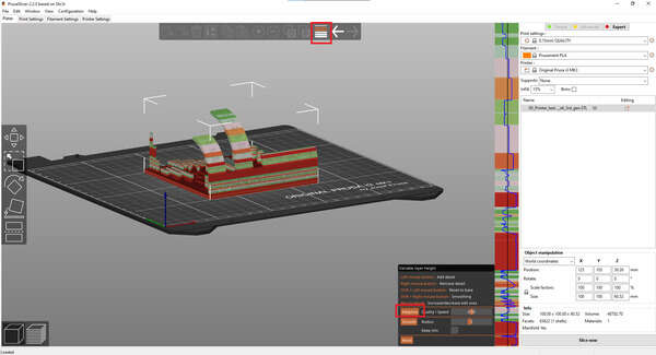
Prusa adaptive layer settings
I later found out about this cool settings in recent Prusa slicer releases: the variable layer height. It allows to specifically set layer speed and resolution for each layer of the part. Even more interesting, it can adapt the layer settings automatically by pressing the adaptive button. It can also smooth the resulting part.
We then tested the clearance using Neil’s design. Once printed, we had to remove the support with pliers and a bit of handwork, not easy but it worked!
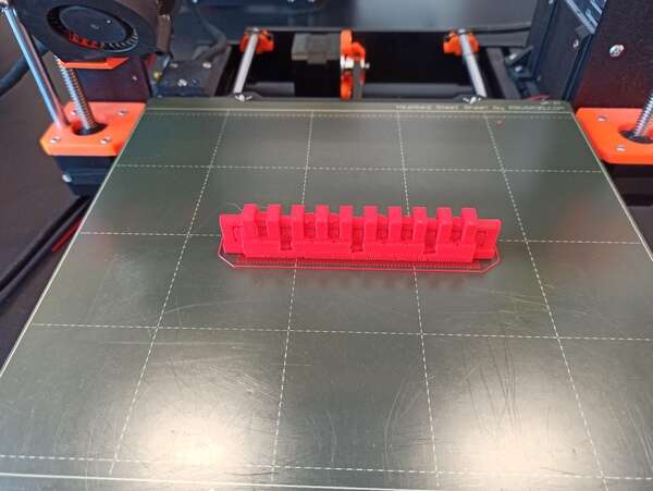
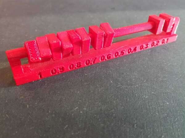
It’s interesting to see that when the gaps get too small, the support cannot be cleared and so the two parts are linked and blocked together.
Imbricated parts: Chainmail
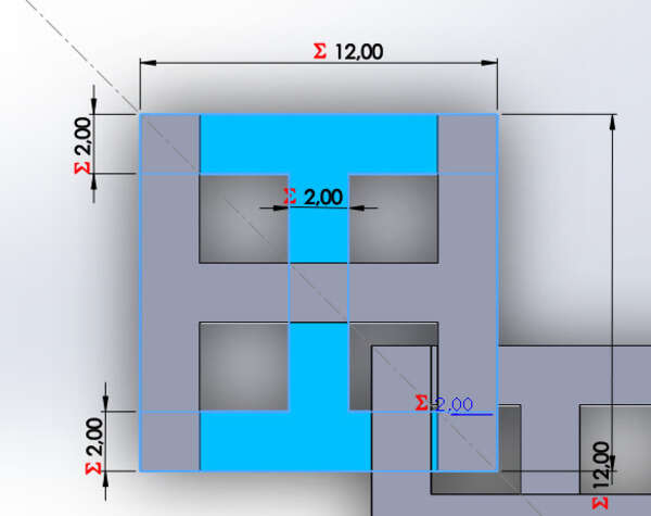
As an example of parts that can be constructed imbricated I decided to design (parametrically !) a chainmail. I did it in SolidWorks and printed it using PLA and a Prusa MK3 printer. My parameters were 0% infill and 0.2mm resolution (0.4mm nozzle).
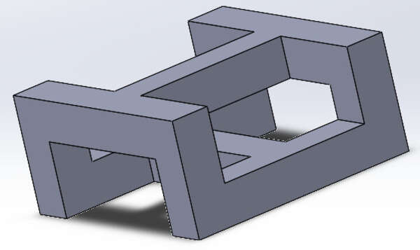
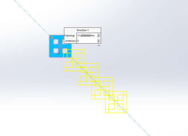
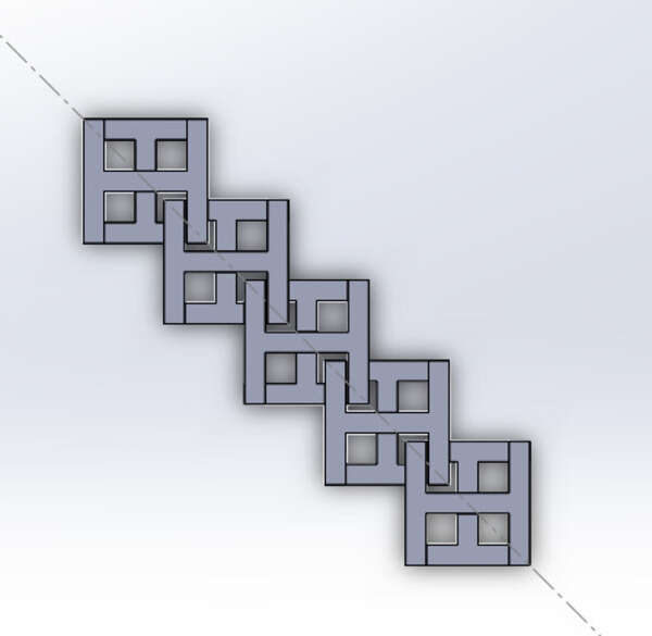
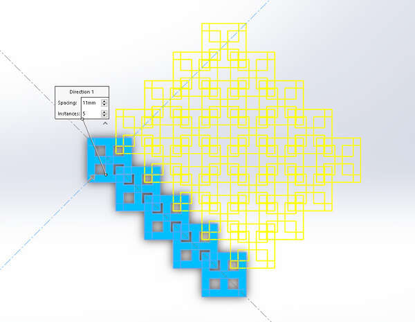
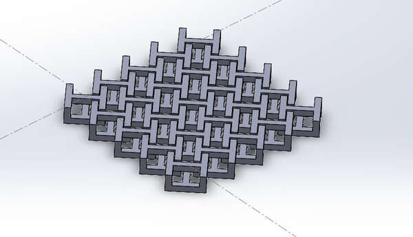
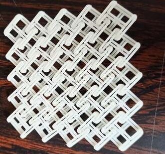
The amazing thing with this is that I could simply export my SolidWorks file to STL and print it as is! A single print !
The mails do not stick to each other! Perfect
Solving my needs: my bike handlebar tape holder
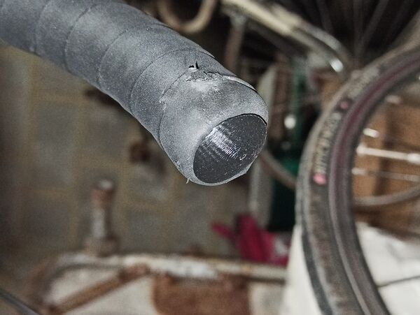
Being able to 3D-print also means that I do not need to buy small, specific parts from manufacturers. In particular, I fell from my bike a few weeks ago (damn ice) and lost a holder for my handlebar tape…
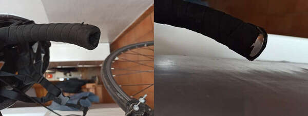
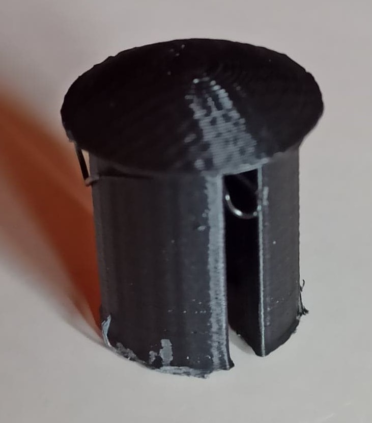
So I decided to unmount the one I still have, measure it and print a new one!
So after the measurements: time to design!
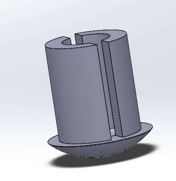
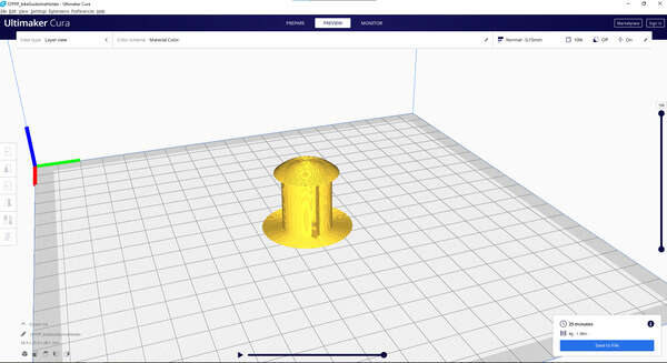
I was a bit scared about the printing as I didn’t really know if I needed support… Eventually, all went well as the bridge was short enough and the overhang on the border was also short enough. Some filaments were a bit ugly under the dome but I don’t care.
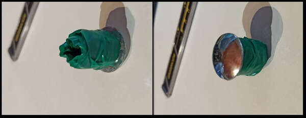
PVA: the soluble filament
PVA is a type of filament that has the property to be soluble in water. That makes it good for two things:
- Printing support that can be easily removed, even inside the part by just plunging the part in water for a few hours.
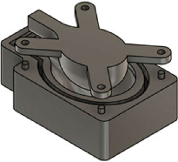
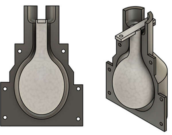
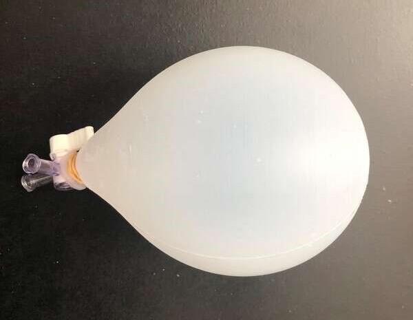
- Make an inner mold for single-cast.
I used it in the past for the latter reason and here is what I obtained.
3D-scanning
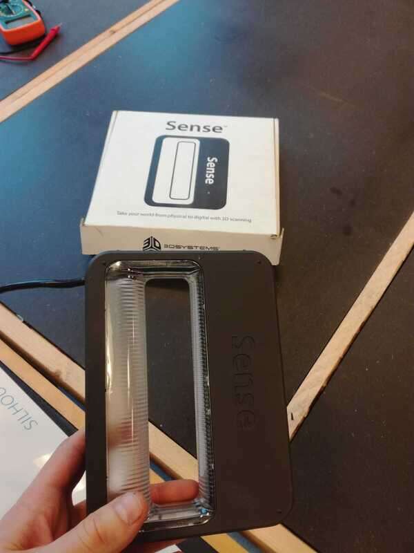
3D sense
At our lab, we have a 3D sense. Unfortunately, the company manufacturing it went bankrupt and the software isn’t available anymore. Bad luck.
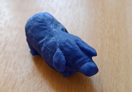
Quentin’s scanner and a Pig
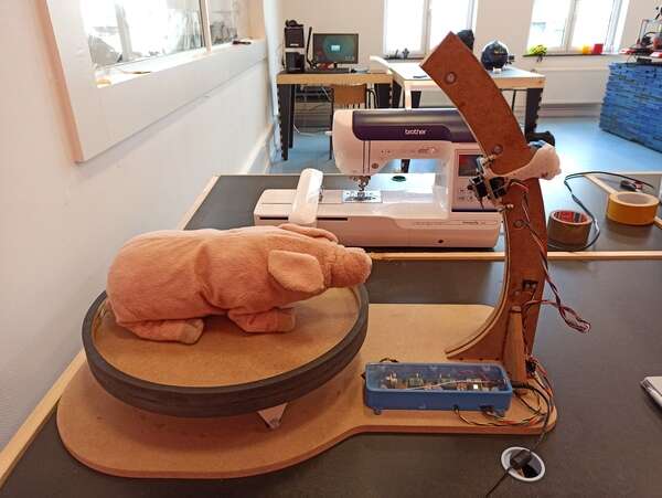
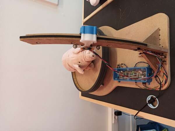
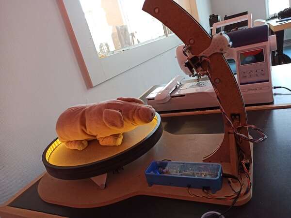
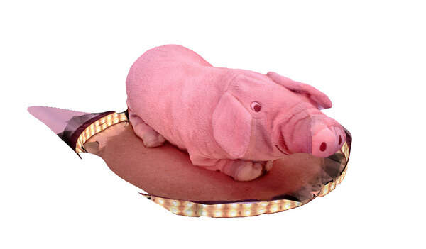
The great news on the other hand is that Quentin Bolsee’s final project is a photogrammetry 3D scanner. It is extremely well done and yields very nice results. I decided to learn how to use it and scan a piggy toy.
It works with an ESP32-CAM mounted on a CNC cut platform. The object to scan rotates on a plate with the help of two motors and the whole system is controlled with the ESP and an ATTiny412.
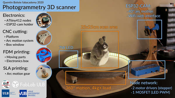
The device can be used and controlled through a web page and HTTP requests.
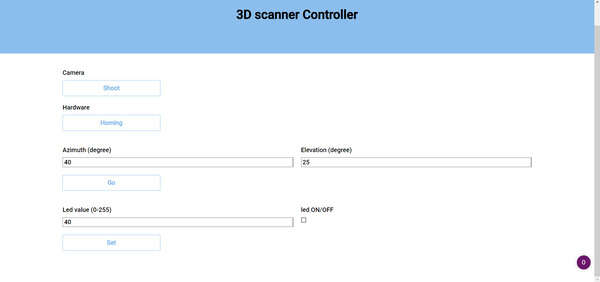
Before launching the automatic acquisition, I first homed the device, and then I took some pics to visualize the illumination in the room and adjust the exposition time. I then tweaked the Python script to get exactly 100 pictures (20 different azimuths, 5 elevations). The code is available at the bottom of the page in the design files. Note that it requires Numpy, tqdm and open-cv.
pip install tqdm pip install numpy pip install opencv-contrib-python
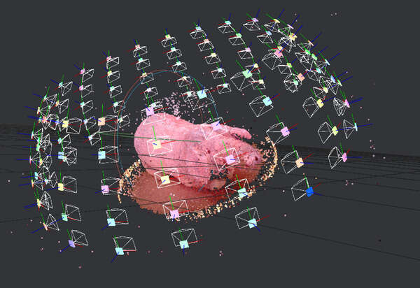
About one hour later, I finally have my 100 pictures. I can then import them into photogrammetry software and see the result ! First, I tried to use Meshroom (AliceVision) which is free! Note that Meshroom uses your GPU for the computation so best to have a nice desktop configuration. For an unknown reason, my GPU was not used a lot though but my CPU was running at full power for at least 30 minutes!
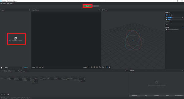
Once done, you can simply open the workign directory folder and the .obj will gently sit there ready to be used !
I then downloaded Autodesk Recap Pro. The software is extremely powerful and is capable of generating a 3D model based on at least 30 images with a maximum of a 100 per project. These images can be simply taken with a smartphone camera without even needing to be in precise spatial positions. It is unfortunately pricey but a free trial exists and just like (almost) all Autodesk’s products, it’s free if you have a .edu mail address.
Recap will then try to reconstruct the point clouds in 3D and you can then slice or adjust the model before exporting it.
The big advantage of Recap is the fact that the computing is done in the cloud! No need for a graphics card
Notes
.edu account have a limited queue so the waiting time is between 2-12hours, no need to panic neither to leave your laptop on, as it is processed online ;)
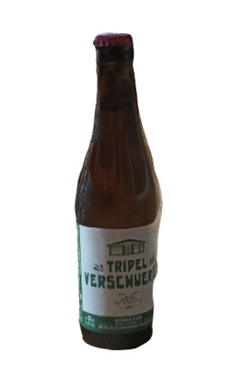
I was first not really convinced by the software capabilities so I took bad photos (no attention to lighting, blur or 3D completeness) of a bottle of beer. Surprisingly, the results were good !
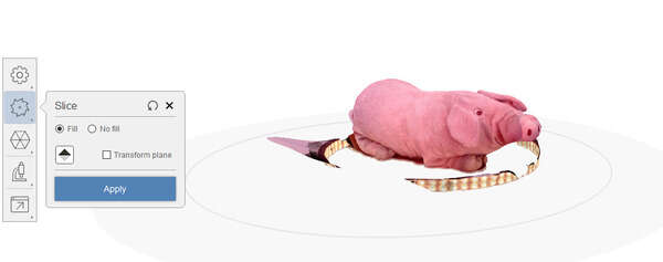
The Edit-> ‘Slice and Fill’ option allowed to slice the object from the environment and I ended up with this:
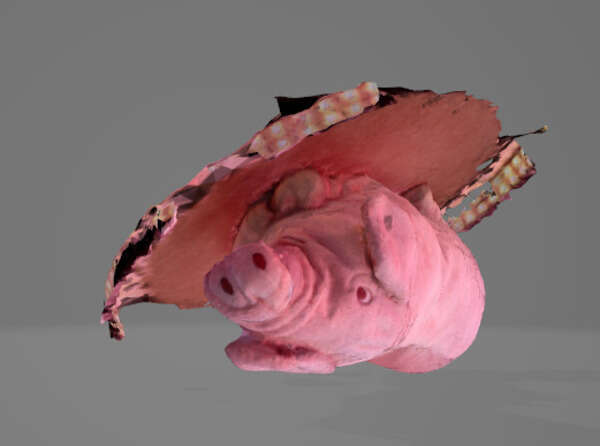
I then imported my pig pictures and here is the result.
Obviously some of the device still remains on the picture but with the edit tools available in Recap I could quickly remove them !
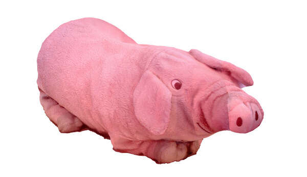
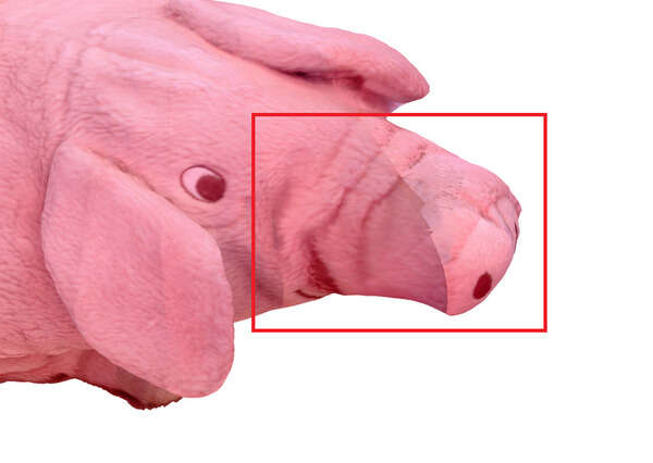
With the lasso tool and the diagnostic tool I could remove the last bits and fill all the holes in the design. It is not perfect but still a very nice result !
I could then export it as an STL before printing it !
All in all, Recap has the advantage of running in the cloud but the waiting queue can be a bit bothersome. On the other hand, meshroom is free and runs locally on your computer. The end results are pretty much similar but Meshroom has more options to play with (intrinsic camera matrices, changing the nodes in the graph editor to alter the results, …) so I guess it is more powerful.
Scanning my colleagues
I then tried to scan the head of my colleague Adrien. I used a video from my phone, captured at 30fps; 1920x1080 pixels and then used ffmpeg to extract all frames as single .jpg files.
Since Recap is limited to 100 photos per project though, I first had to reduce the number of frames.
Given that I had an initial 20 seconds videos (596 frames exactly), I reduced my video to 5 fps before extracting the frames:
ffmpeg -i Adrien.mp4 -filter:v fps=5 AdrienLowRate.mp4
And I ended up with exactly 99 frames:
ffmpeg -i AdrienLowRate.mp4 thumb%04d.jpg
Well… It failed (absolutely nothing but a ball of unusable texture). I think this may be because some of the pictures did not capture its entire face and maybe the background was too uneven. I’ll try again.
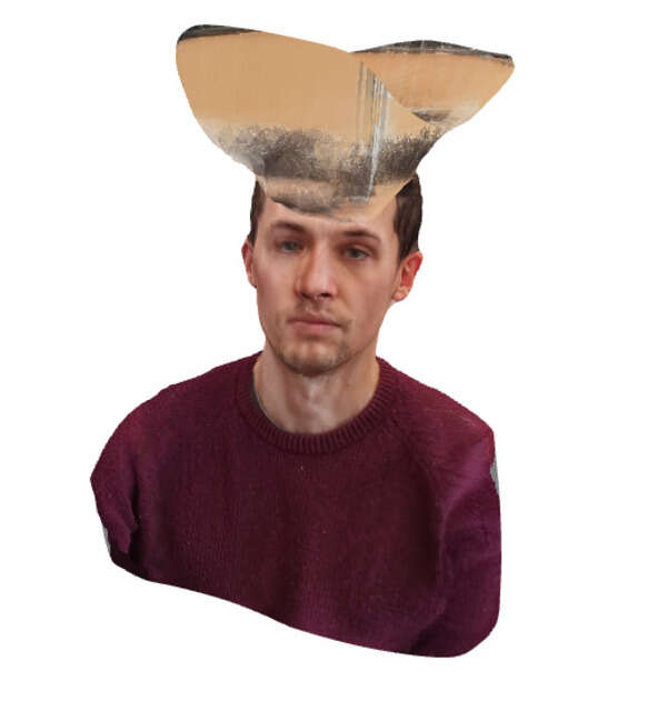
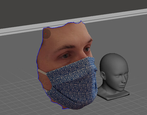
I then simply took some pictures of my father’s head (about 30 pictures) and it actually worked way better. Now the back of the head was very inaccurate because of the hair but the front of his face is actually quite impressive:
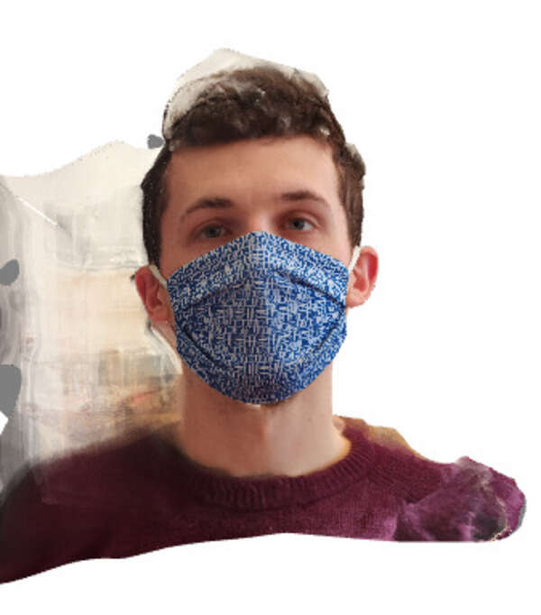
Finally, I tried the same on two of my other colleagues: Max and Gilles. For both of them, the video method worked a bit better but with a big artifact probably because of their hair.
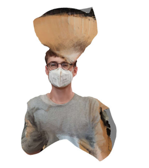
I then tried using only pictures taken with my phone and that yielded better results !
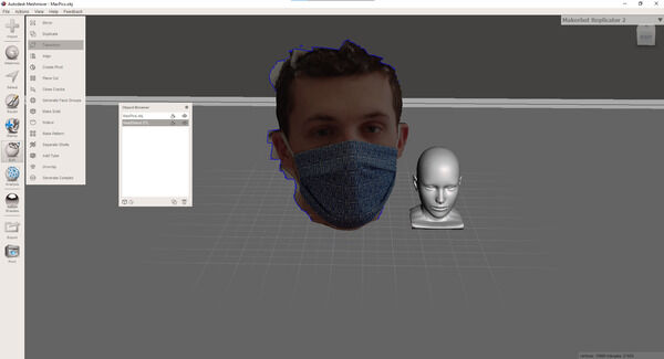
Modifying the mesh
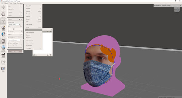
I then wanted to play with the mesh a bit and the sculpting options in Recap are quite limited. I installed MeshMixer, another Autodesk product. I first tried to place my father’s head on a headstand to deal with the issues at the back of his head. I first used a smoothing Brush to smooth the mesh and made a solid out of the result to close the gaps. Different options are available (accurate, fast, sharp edges preservation, …). Reducing the cell size to a minimum gives the best result and preserves the initial slight bumps and such. I then followed this Meshmixer tutorial to append and mix multiple meshes and objects.
| Illustrations | Description |
|---|---|
 |
To move the head: edit -> transform, clicking on the center square for scaling |
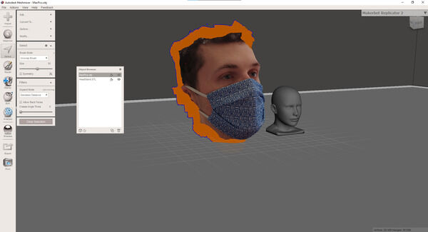 |
Select (S key) then brush to select and b to smooth the boundary |
 |
Then x to delete |
 |
Do the same for the headstand |
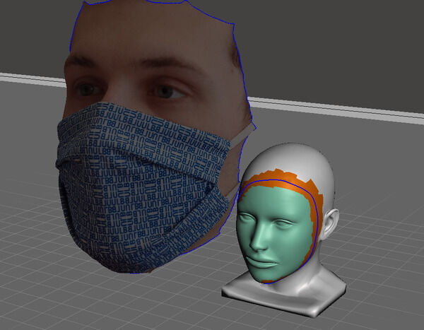
 |
Shift click to select both then combine |
 |
S then double left click to select the whole boundary Edit -> join |
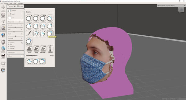 |
Then brush to shrink smooth everything |
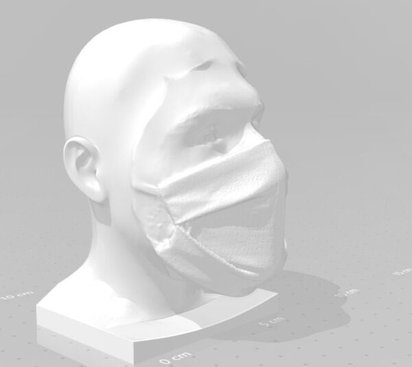 |
Export to STL |
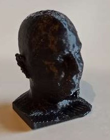
You can then print the resulting STL !
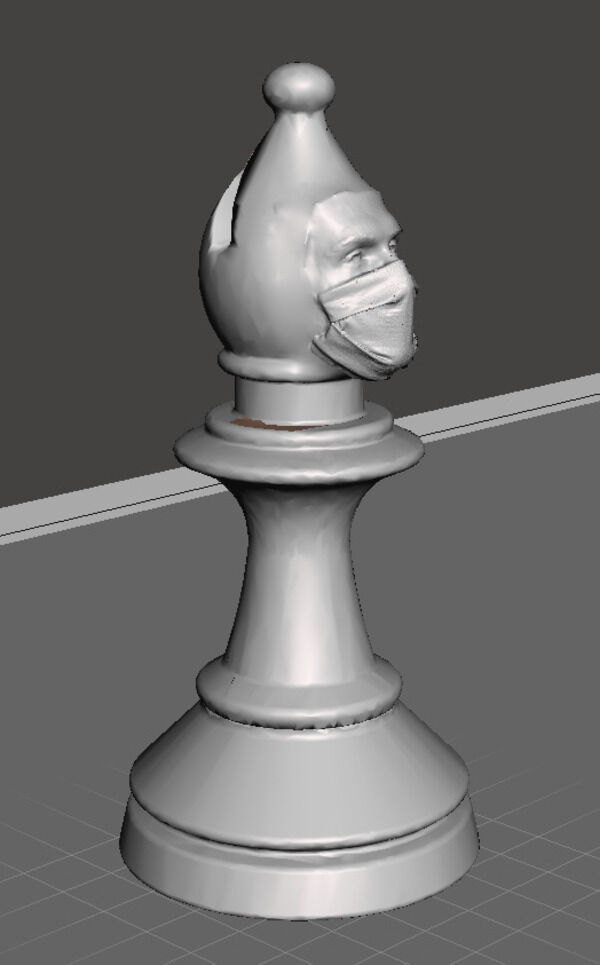
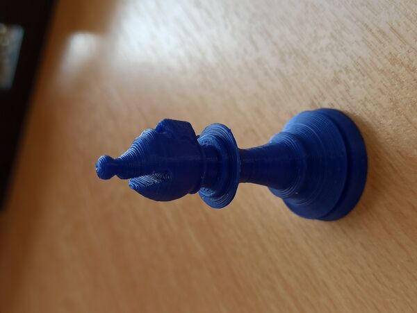
Making a chess piece
I redid the same step as above but this time with a Bishop STL I found online. I ended with an almost nice bishop with my colleague’s head ! I plan to do the whole department in the coming months !
To go further
I would like to use a resin 3D printer to make other parts and compare the results. I plan to finish my chess game whenever I got time. I want to implement OctoPrint on my Uni’s printers to be able to print from everywhere in the building and monitor the printing. Play with the independent layer settings in Prusa to optimize my printing time. Test infill patterns mechanical anisotropy to make structures that are rigid in a direction and deformable in another one.