6. Electronics Design
Objectives
- Group assignment: Use the test equipment in your lab to observe the operation of a microcontroller circuit board.
- Redraw an echo hello-world board, add (at least) a button and LED (with current-limiting resistor). Check the design rules, make it, and test it.
- Extra credit: simulate its operation
Introduction
This week is about designing a printed circuit board that is, at least, capable of lighting up a light-emitting diode and make use of a button.
Jason and I started by experimenting a bit with the test equipment available both at the lab and at Uni before trying to make a design using the NeoPixels.
We thought a bit and decided to try to make a 14-segment display using the NeoPixels and a SAMD11C. Spoiler alert: that was maybe a bit presumptuous !
Testing some circuits with lab equipment
Some of it is repeated on the group page.
SAMD21 and Logic Analyzer
For the group assignment, we had a look at our instructor Quentin’s new circuit which is using a SAMD21E18. This little chip is able to act as any device including keyboard, MIDI, serial device and so on…
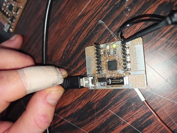
Also, it can be directly programmed using Python which is extremely nice and is able to communicate (using the Python’s libraries) using SPI, UART, I2C and others.
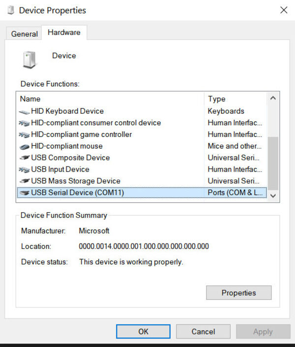
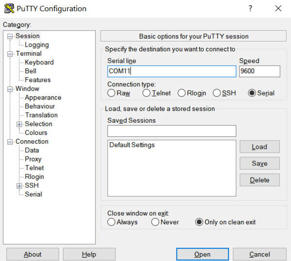
Since we’ve seen that the µ-C is available on COM11, let’s try to communicate with it using Putty, a terminal emulator !
Once the communication is established, the code resets, runs and finally finishes. On the board, we see a LED blinking 10 times.
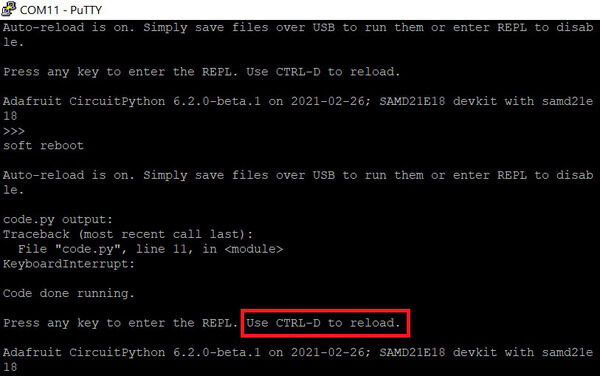
Opening the “code.py” file we can see the following code that runs in the µ-C:
1 2 3 4 5 6 7 8 9 10 11 12 13 | |
This code basically sets the PWM duty cycle of the pin controlling the LED to a continuously increasing and decreasing value, for 10 cycles.
By adding the print statements, we were able to also monitor the code run in the terminal !
We then tried to use the Python interpreter inside the µ-C to play with the LED.
First, we familiarized ourselves with the library used:
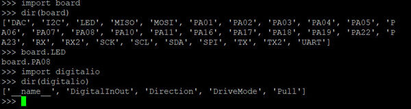
We can see that the “board” module contains all the available pins, some are named by their functions “LED”, “I2C”, “SDA”, … We can also see that the board.LED pin is in fact the pin 8 (or board.PA08). By importing the “digitalio” module we can see that we can program the pin to be either input or output and the digital value of it as well as its pull-up.
Let’s try to light the LED using the Python interpreter:
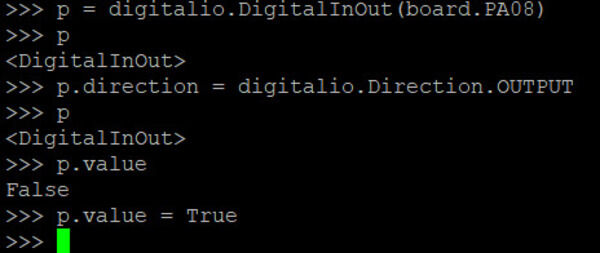
It works (oops, forgot to take a pic !). Let’s make our own code to blink the LED and see the result :
Great ! Now that we visually see that it works, let’s try to measure it using other tools.
The Saleae Logic 8 analyzer
Blinking LED : PWM
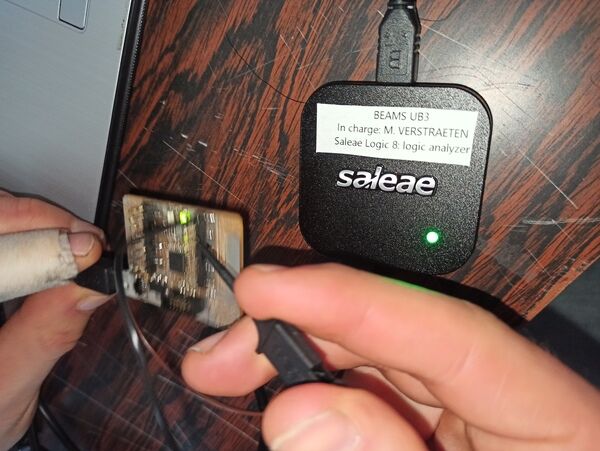
I recently bought a Saleae LA for the Uni but didn’t have time to test it. Now is the perfect time ! We connect the mini-probe to both the ground and to our pin and plug the LA via USB to the computer.
Using the Logic 2 software we can start recording ! The nice thing is that the LA can record both the digital (upper row) and the analog signals (lower row). We can therefore have a look at the shape of the signal and detect any interference or issues with the signal itself.
Let’s try to change the output of the pin:
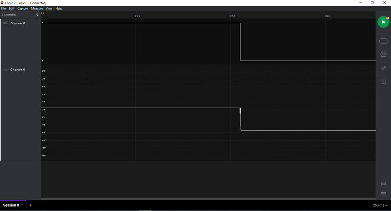
Now let’s run our blinking code:
On this large scale we clearly see something.. But what is it ? First, we need to understand that we just like before, we are modulating the duty cycle of the PWM signal. Basically that means that we go from a 0% high time/low time to a 100%.
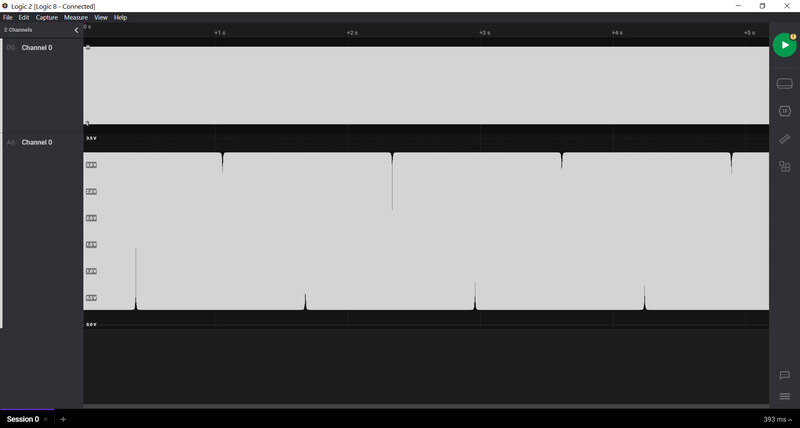
Let’s zoom in:
We see some spikes ! Actually they are the PWM signals with a very low duty cycle (i.e. close to 0%). Whenever we reach the lowest point, the voltage isn’t even able to reach the “high” state.
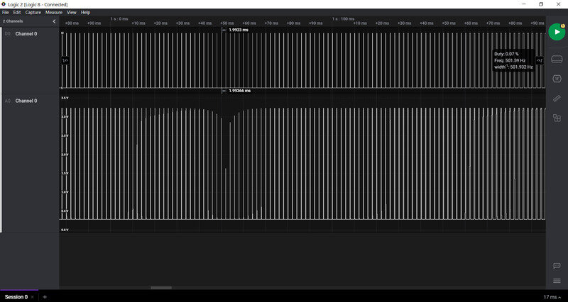
Zooming even more:
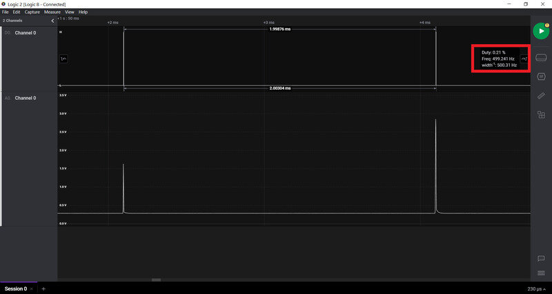
Here we clearly see that the spikes are actually very low duty cycle PWM.
Let’s have a look at the “high duty cycle” part of the signal:
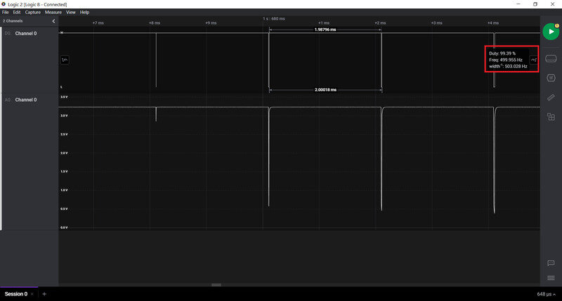
Here similarly, the voltage cannot reach the low state at high duty cycle.
Finally, let’s look at the signal in the middle
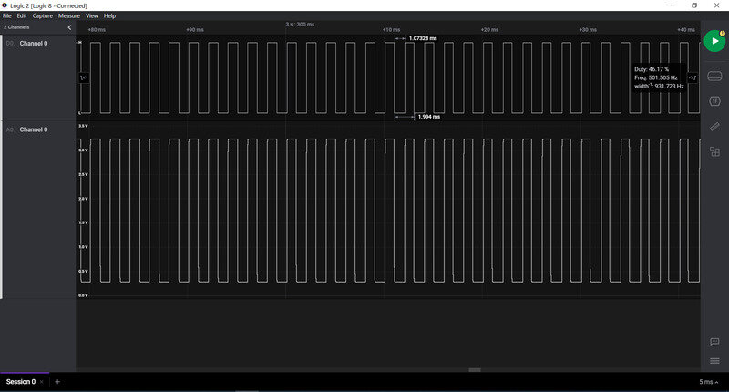
Just like we expected, we here see a very nice PWM cycle.
Communication protocol
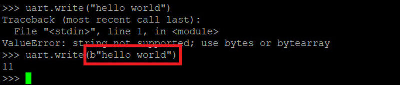
We then tried to observe the signal that happens when communication occurs. First, we tried to enable the I2C protocol but it requires pull-up resistors on the SDA and SCL lines which we didn’t have. We then tried the UART protocol but couldn’t make it work for whatever reason (maybe the RX pin was not pulled down correctly ?). But when we tried to communicate we noticed we needed to explicitly send the message as bytes using the “b” flag.

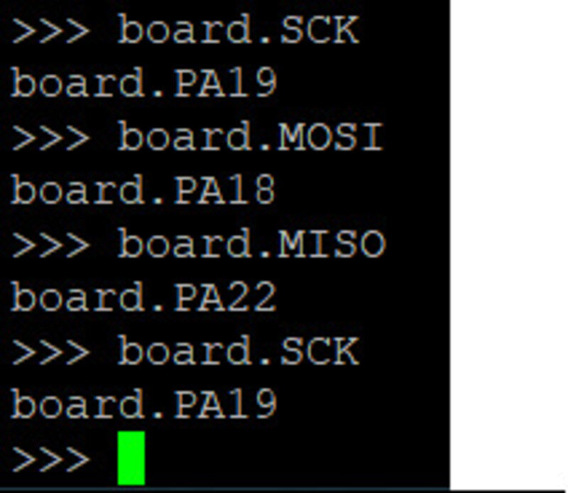
Finally, we tried the SPI which needs 4 lines (MOSI, MISO, CLK and SS/Enable). We found the corresponding pins:
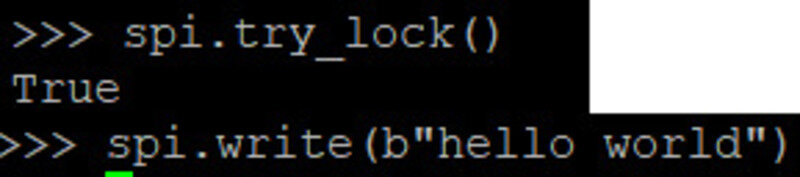
And we “locked” the communication to be able to write the message:
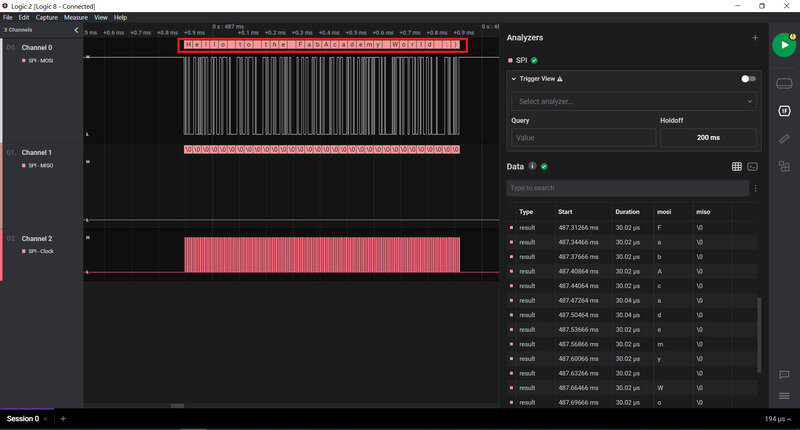
Let’s analyze it in Logic 2:
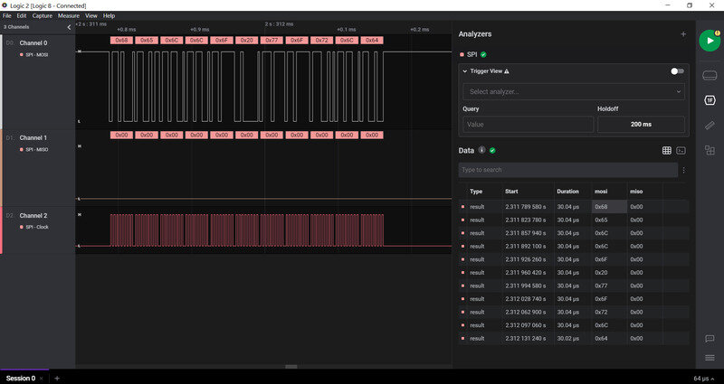
Now the problem is that the message appears in hexadecimal, let’s change the encoding!
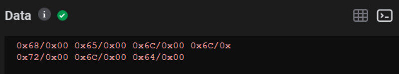
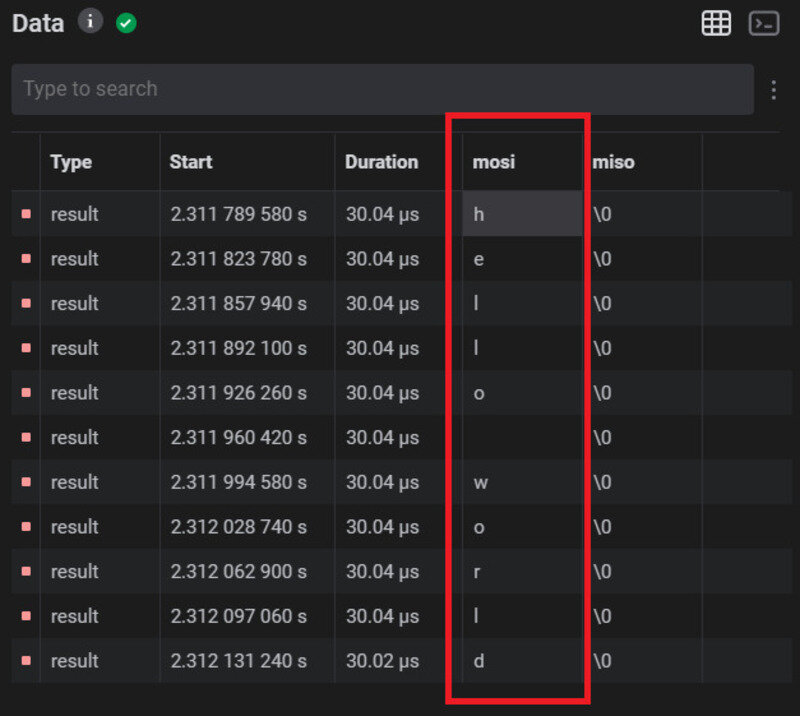
We can now try to send a different message! What about “Hello to the FabAcademy world!” ?
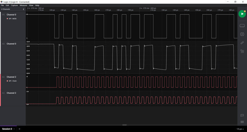
And let’s have a closer look at the shape of the analog signal
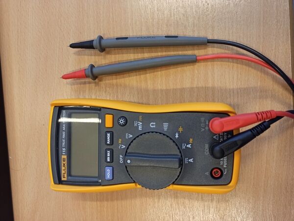
Multimeter
At Uni we also have a Fluke 115 multimeter. The best use for it is to check for continuity to detect defect tracks that are either short-circuited or open-circuit (and shouldn’t be). It can also be used to check the value of resistors or the direction of a diode.
Oscilloscope
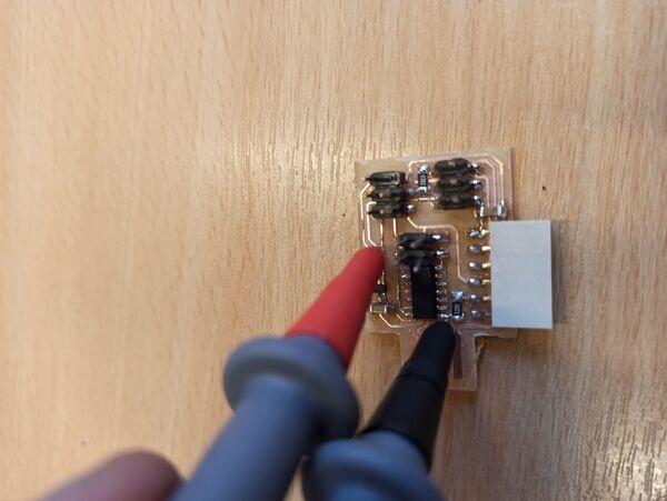
We also used a MSO5104 oscilloscope to check the output signal of my previously designed PCB and the “analog” pins of an Arduino Nano and Arduino Due.
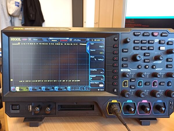
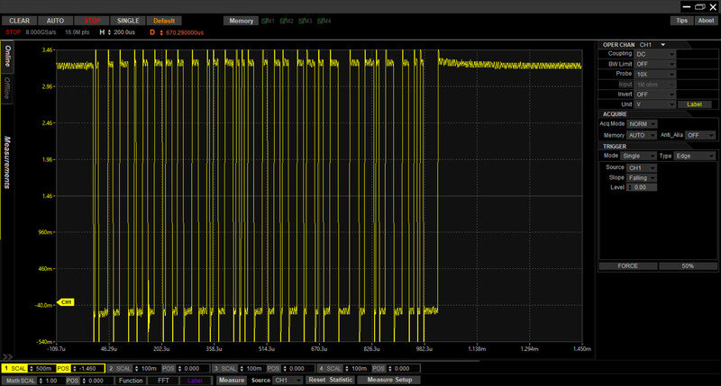
The Arduino Nano is unable to provide a real analog voltage as it lacks digital-to-analog converter. When using the command analogWrite(value) it actually outputs a PWM signal whose duty cycle is proportional to said value.
The Due however features a DAC and can output analog voltage.
Designing a board
This week I chose to use Altium as my PCB drawing tool as it is the main one used at my Uni and I have trouble using it (I’m more used to Eagle) so let’s try to get something done with it.
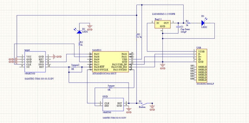
ARM programmer
During week 4, I tried to use a design proposed on the FabAcademy website to make an SAMD1-based ARM programmer. However, I ran into some issues, mostly due to the very small width of the tracks and the lack of status LED. I therefore decided to make my own board in Altium.
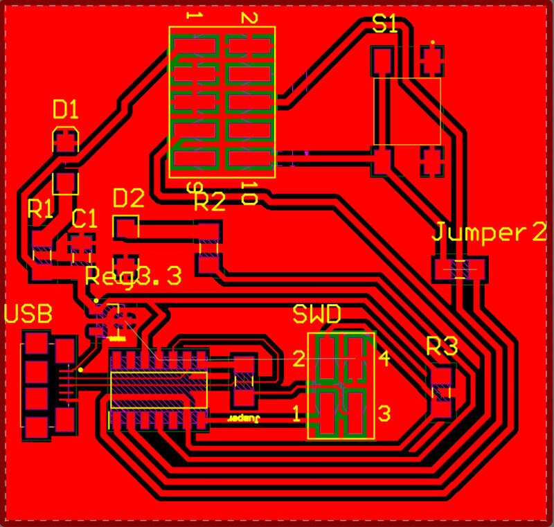
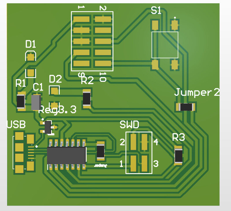
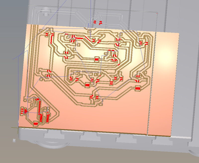
I based my design on other boards but I wanted to add a LED on the 3.3V and on pin 14 to have a status LED. Moreover, I wanted to have wide tracks (at least 20 mil on almost all of them, up to 50 mil) to reduce the risk of error due to CNC engraving and ease the soldering and debugging. I added a button to pull-down the reset pin and restart the µ-C or allow programming. I also wanted to have a ground plane to reduce the tear on our milling bit and reduce the potential interferences. Finally, I added a micro USB B connector.
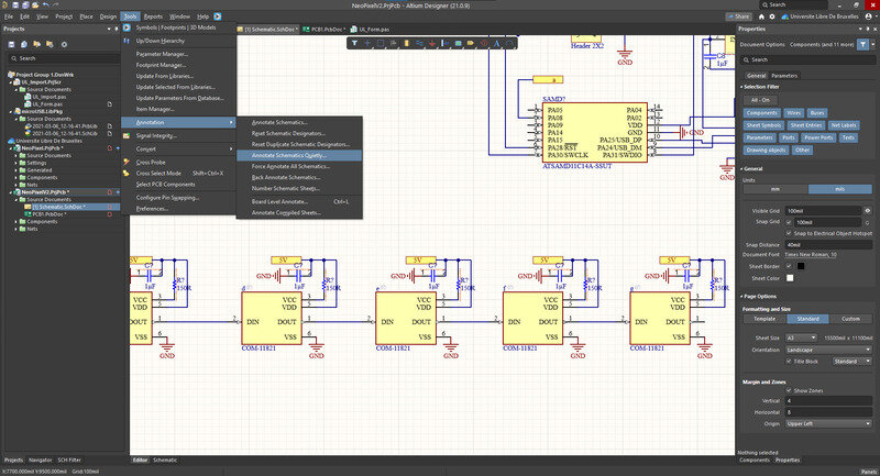
A small tip I learned in Altium is that if you don’t care about naming your components like resistors and capacitors, you can ask Altium do it for you (naming then from 1 to … from the top left corner to the bottom right) using the “Annotate schematic quietly” tool.
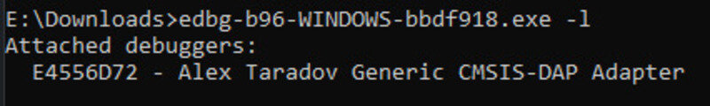
I then wanted to load by bootloader using edbg. However, I ran into a few issues. First of all, I made a mistake in my Altium design during the routing: I unfortunately deleted the VDD route which is the supply to my µ-C. This was easily fixed by adding a small jumper wire and UI fixed the PCB for later use.
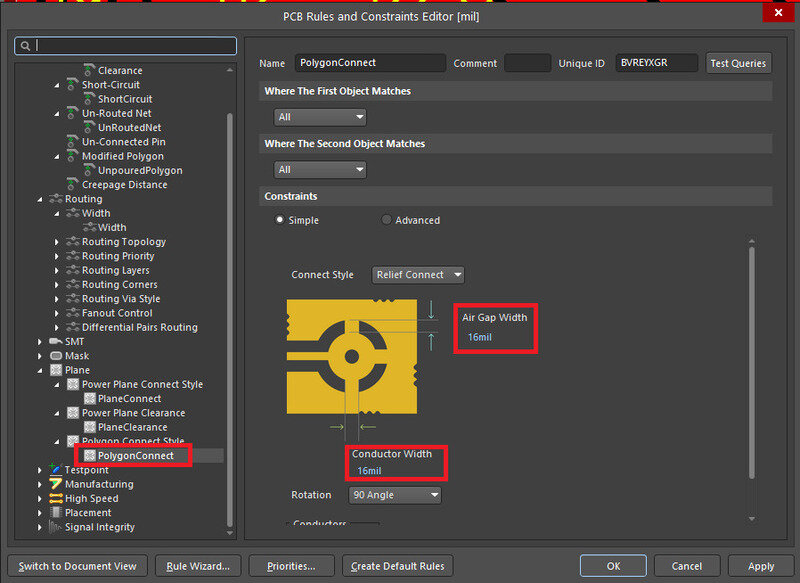
To make sure the milling bits are able to cut between the tracks and the ground plane, the clearance msut be minimum the diameter of the bit. In our case, that is a /64” bit so 16mil is the perfect setting. Note that I had to modify some footprints like the USB connector for it to fit.
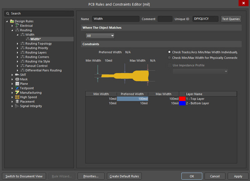
Regarding the ground plane, I ran into a small issue that is that the conductor gap was a bit too small leading to the fact that grounded pins do not present any pin (as they were too thin to be cut with the CNC). A simple design rule can be changed to overcome this !
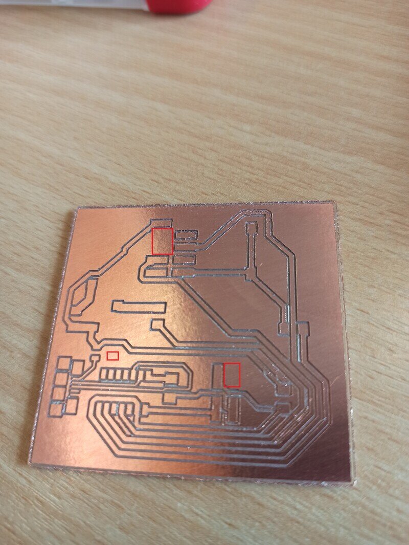
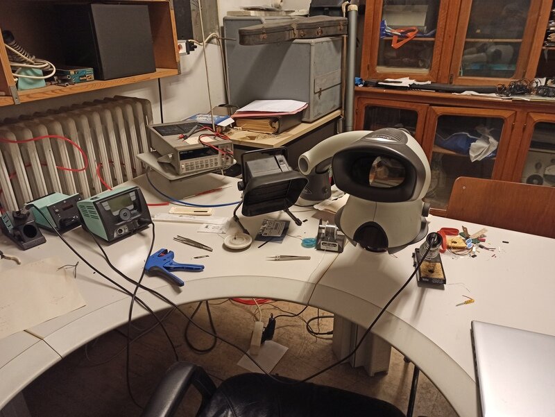
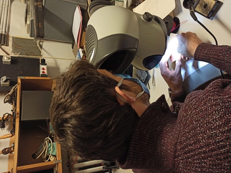
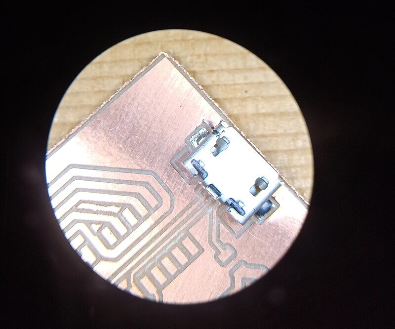
I used the excellent binoculars at my Uni to be able to cleanly solder the µ-C, the microUSB connector and the voltage regulator which are really tiny.
Then, I noticed I still couldn’t program my µ-C. Looking at all the traces I finally found that my reset pin was shorted to ground. I had a lot of trouble finding the short location and I ended up cutting traces around until I found the actual short was under the button…
Bad news, I ended up tearing my SWD programming pins and I still couldn’t program.
Bright side is Jason did engrave another board of my design and soldered it. It worked with no issues as I expected 
Once the frustration had passed, I soldered new pins directly on the tracks:
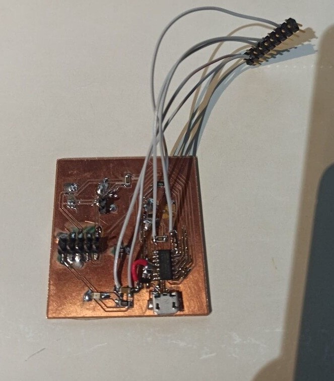
And I could finally program it. Since I had some doubt about edbg, I tried the Segger “Flasher” programmer that was available at work and used the Segger J-Flash software in the V6.44e version.
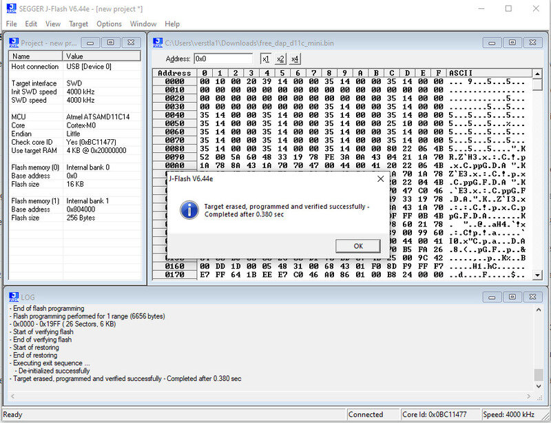
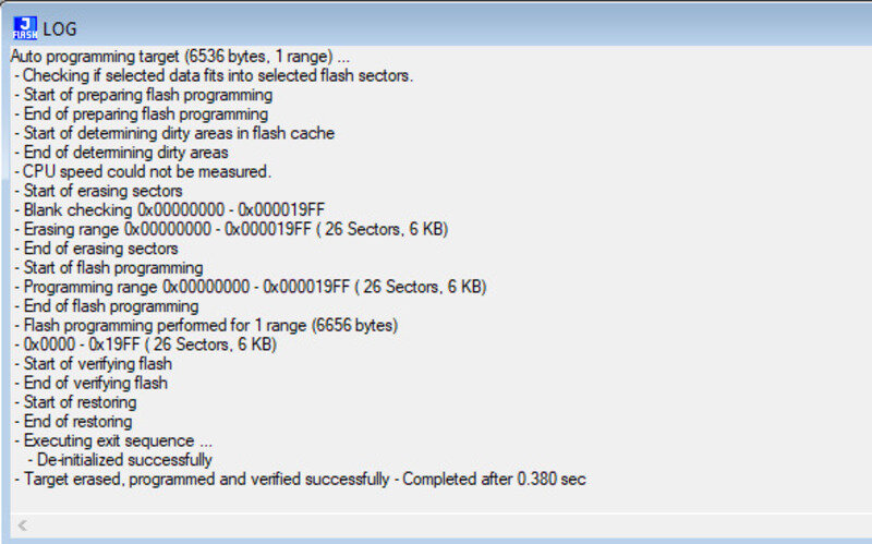
Finally, I could program my SAMD11 !
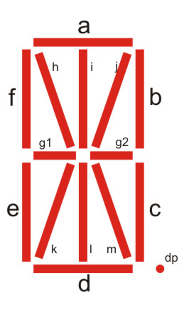
7/14 segments display
1. 14 segments display
I then tried to do something big: a 14-segments display using NeoPixels. Neopixels are addressable RGB LEDS that are controlled using a single control line and the data is sent from the first LED controller to the last followed by a confirmation/update sequence. They in fact are WS2812 LED Driver IC that control 3 LEDs (RGB) and the whole thing is placed inside a 5050 LED package. They would therefore be perfectly suited for my needs: I can control my 14 LEDS using only one output pin (given that I have a reliable clock on the µ-C).
I first mentally drew the schematic and what I would need: - µ-C: SAMD11C - Resistors (current limit and jumpers if needed) - Decoupling capacitors - Voltage regulator 3.3V - USB connector - External 5V supply ? - Quartz ? Probably not…
For the external supply I quickly calculated that I would need it as the LEDs pull about 60mA (3x20mA, RGB) at 5V which means 0.72A for 14 LEDs which is more than the µ-C can handle and the USB can supply (max 0.5A)
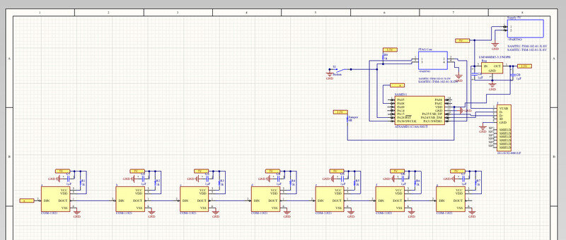
I then did the schematic only to realize there will be a lot of components. In particular, each neoPixel requires a 150Ohms resistor and a decoupling capacitor along with the GND and VDD supply.
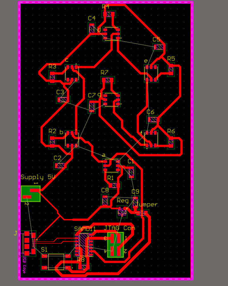
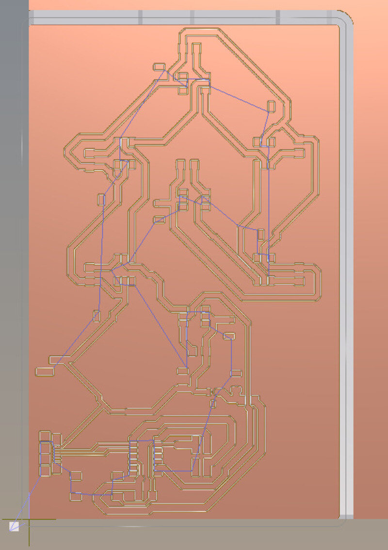
Just placing the components on the PCB looks like this in ratsnest:
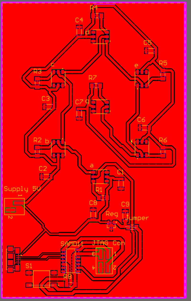
With a bit of time and effort I ended up with this.
However, I did not take into account the clearance (oops I forgot…) and my board was actually too big for the FR1 copper plate that we use.
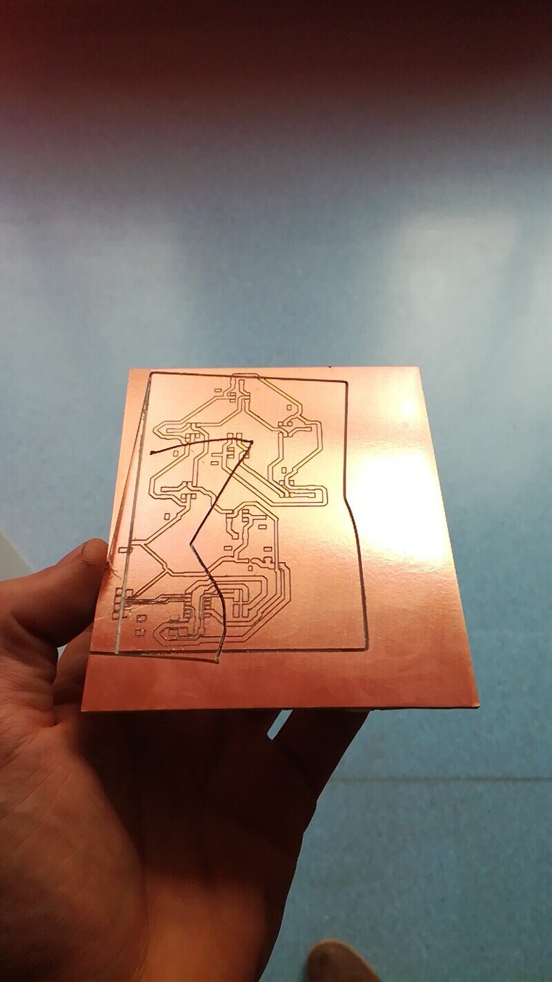
2. 7 segments display
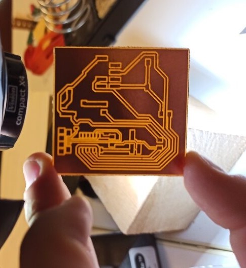
I therefore had to redo it, so let’s be humble and (re)start with a smaller challenge: 7 segments only.
This time it fits in the FR1 copper plate
However the double-sided tape did not stick well enough and well… a wasted copper plate…
Code
Since NeoPixels require very precise commands and timings, let’s use designed libraries to use them: FastLED and AdaFruit Neo Pixel. However, FastLED does not support the SAMD11C so we’ll have to try with AdaFruit’s first.
Not yet done…
The laser cut pattern and vynil cutter
To make it more like a real 7/14 segments display, we laser cut and engraved a plexiglass sheet to make it diffuse the light and we plan (not yet done..) to do the same (but inverted) pattern on the vynil cutter on a black material.
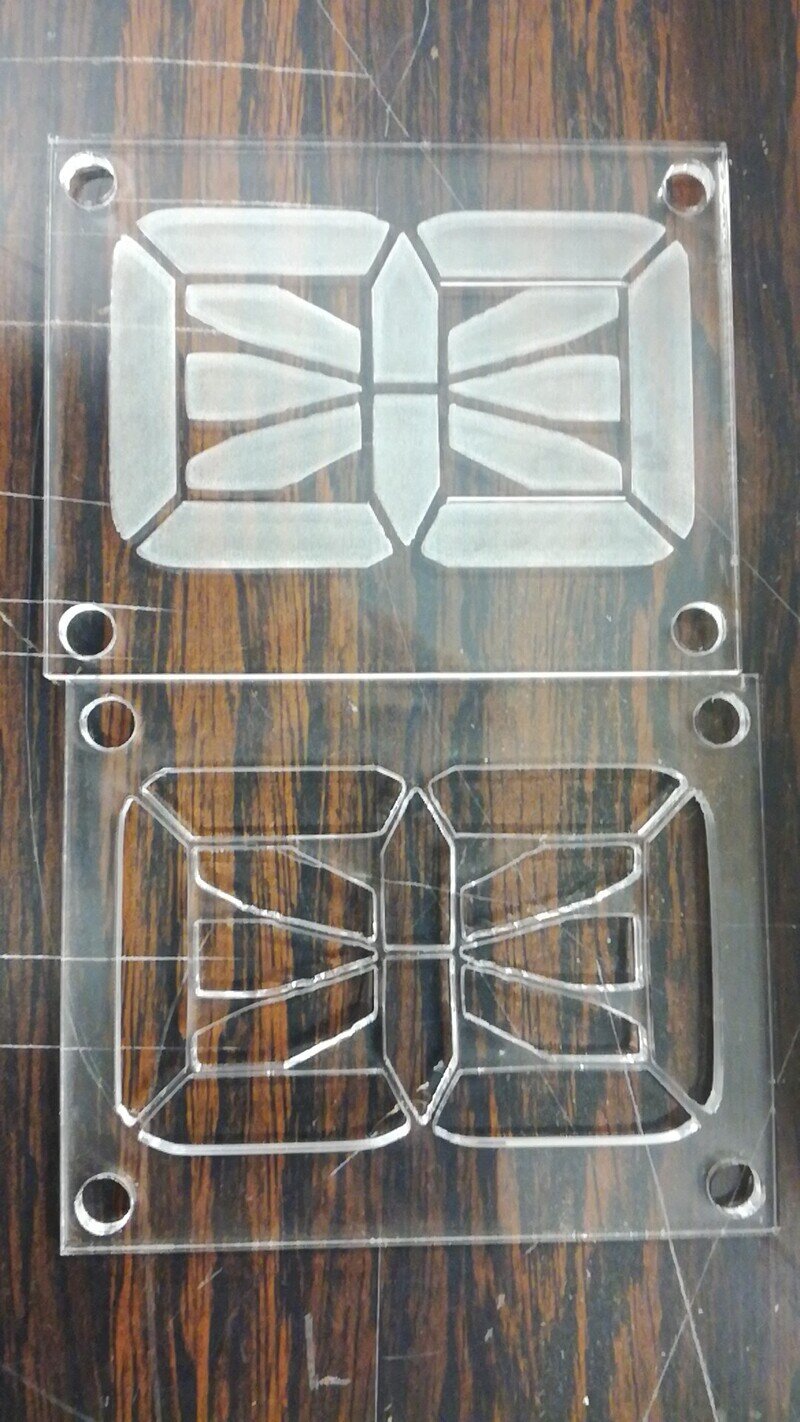
Unfortunately, it does not diffuse the light as well as expected so a better method should be used for better results.