10. Input Devices
Objectives
- Measure something: add a sensor to a microcontroller board that you have designed and read it.
- Group Assignment: probe an input device's analog levels and digital signals
Group assignment
Jason and I already used a logic analyzer and an oscilloscope in the past few weeks some inputs and outputs (see here).
Introduction
I’ve had the opportunity to play with input devices already during the past few weeks so we’ll dig a bit deeper. Moreover, I designed an ESP32 board two weeks ago but I couldn’t finish it in time so it is the opportunity to do it now.
ESP32 board
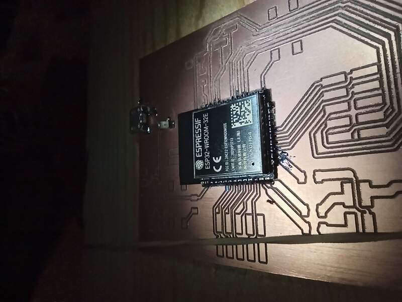
Two weeks ago, I made this board:
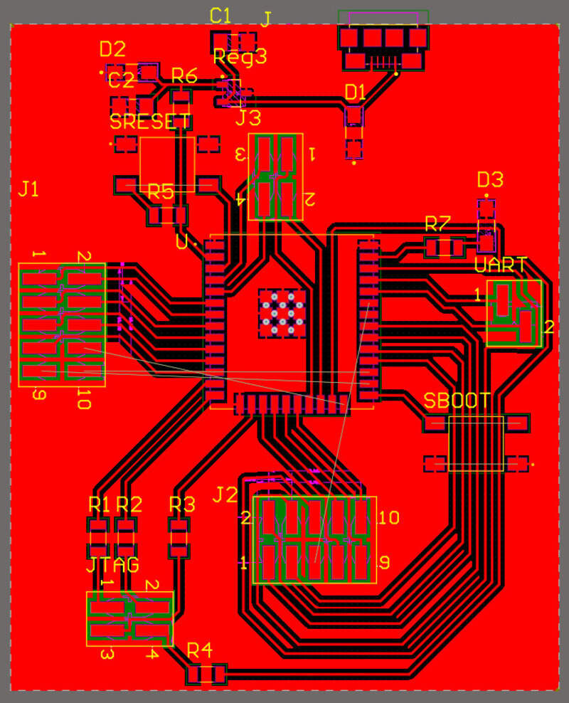
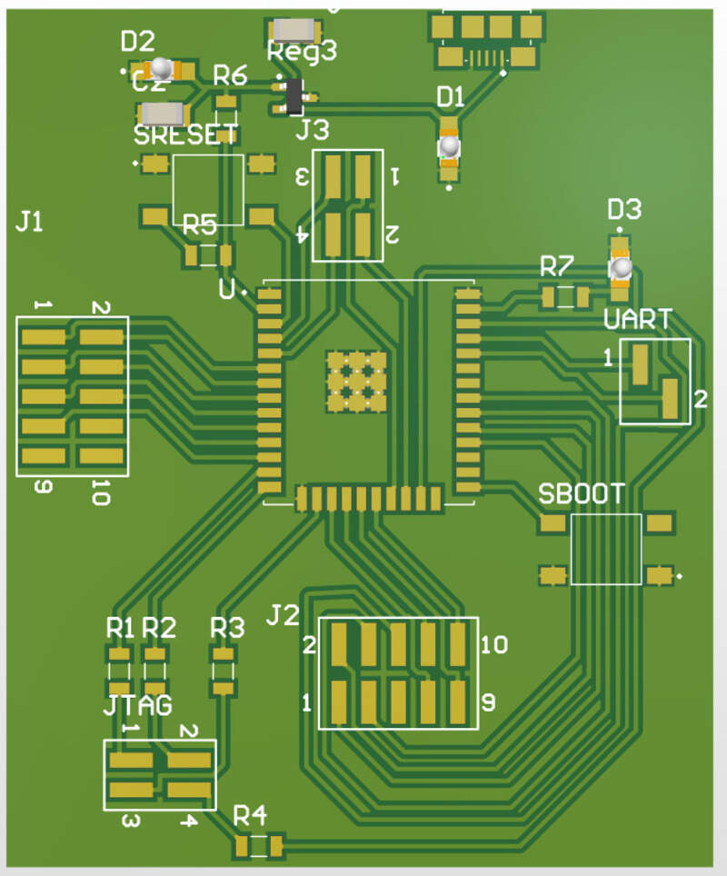
Which is basically a development board for the ESP-WROOM32 microcontroller. I chose to use an ESP32 for all the possibilities it offers. Mainly:
- Integrated WiFi and Bluetooth
- 3.3V FPIO voltage, with intern regulator for 5V power supply
- 2 ADC channels
- Integrated crystal of 40MHz
- SPI, I²C, UART, … compatibility
- Antenna and radio capabilities
- 2.5GHz processor
Most of it is overkill for a simple project but that’s the whole point of making a development board: being able to develop anything with a single chip.
Making and soldering the board
Instead of going with chemical etching (I still miss the ink cartridges just like last time) I can now mill my board as we had an FR1 boards arrival.
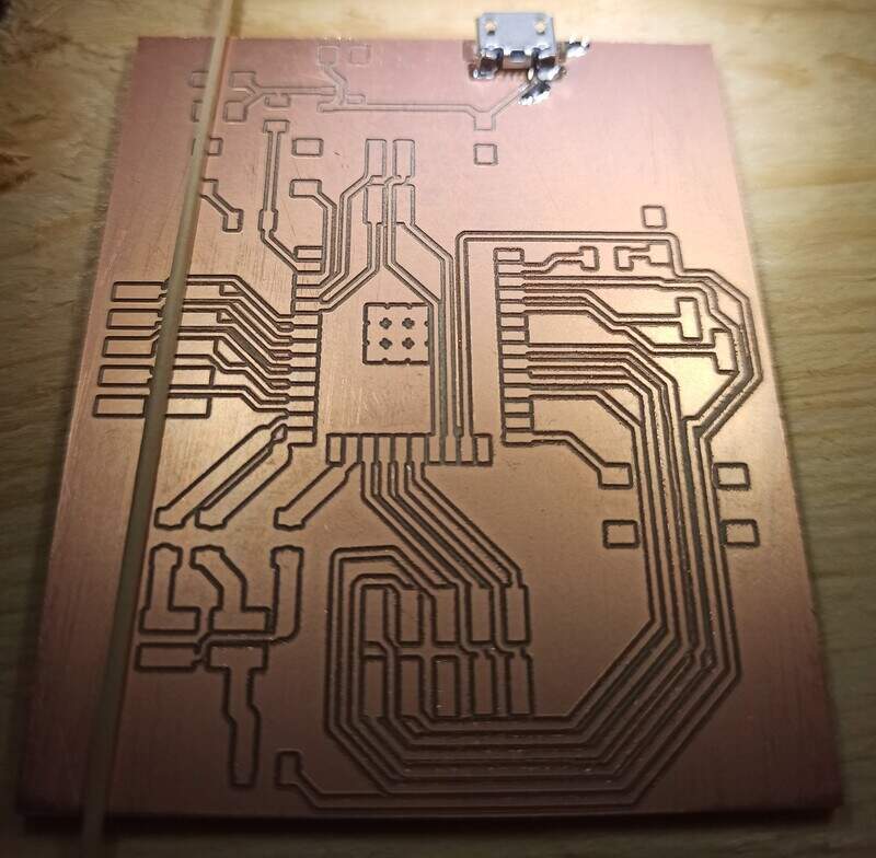
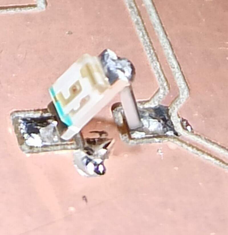
Since I couldn’t produce it before, I only noticed this week some issues about my board: The main one being that I forgot adding two current limiting resistors on two LEDs (D1 and D2). Luckily I noticed it during soldering so I could repair that mistake.
Also, during production, I once again had the issue that ground pads are completely isolated like other pads instead of being connected to the ground plane… I thought I fixed that issue in electronics design week but it seems that the Bantam Tools CNC machine didn’t remember the settings or something else gone wrong. Again, easy fix to add small pieces of wire to correct that.
More ground pins would be useful to add here and there, especially near the UART connector.
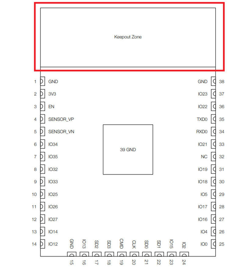
The ESP32 has a “keep-out zone” (I think due to the antenna) which was not indicated on the footprint I took online so two pads are not accessible anymore.
Finally, a strong pull-up would be needed on GPIO0 to make sure we boot in SPI mode and not in download mode by default (it works sometimes but a strong pull-up would help make it more reliable). Otherwise, you sometimes need to short 3.3V and the GPIO0 to be able to enter the SPI mode.
Soldering the ESP32 is not an easy task by itself as the package is almost like a QFN, meaning you have to “push” the solder underneath the pads to make a good connection. Anyway, with a bit of practice, it’s a matter of minutes.
All in all, the ESP32 can be programmed easily and works well so it’s not as bad as it may look  .
.
Powering the board
The ESP32 can be directly fed with 5V as it features a built-in voltage regulator but then you need to make sure to supply it on the “Vin” pin. Otherwise, I implemented a voltage regulator and the 5V can come from a mini USB B connector. The 3.3V is then fed to the same name pin on the board (top left corner).
Programming the board
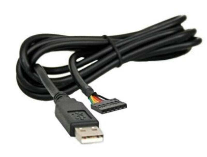
Devkit usually features a CP2102 USB-UART converter chip that allows for direct programming using the USB connector. A ROM Bootloader is built-in on the ESP32. You cannot remove it either deactivate it (though you can load a second bootloader on top of it if needed). This bootloader is able to look at incoming data to see if it is a programming hex file. If so, it will be possible to program it using UART or JTAG. In my case, I chose to use the UART connection (RX and TX pins on the right-hand side of the ESP32). I still need to convert serial data (from the USB out of my computer) to UART. I used a TTl-RS232-3V3 which is a TTL to USB converter cable.
By having a look at the (datasheet). we can see this pinout:
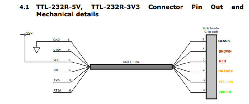
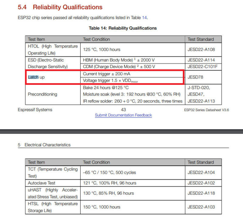
We will therefore connect GND to GND, and make sure to connect RX_cable to TX_ESP and TX_Cable to RX_ESP! Do not connect VCC as the USB is 5V and the ESP32 will already be powered by either its own USB or another supply. I did this mistake but luckily, nothing went bad as (I think) the ESP32 went into latch-up mode when it happened to prevent any damage. I noticed my mistake as soon as I turned on my power supply and it flickered between 3.3V and higher. I’m not completely sure as a latch-up mode can be destructive for the device and it worked well after that some maybe the current flowing was limited? In any case, everything was okay but I’ll make sure not to do this mistake again.
Note that using this cable will require drivers for Windows and Linux that are available here.
To program the ESP32, you need to build the hex file and then feed it to the UART. You can do it either through the manufacturer tool: esptool which is a Python utility to program the ESP32.
It can be installed easily with pip:
pip install --upgrade esptool
Otherwise, you can use the Arduino IDE. You need to add the ESP32 Arduino core either from the Github link or through the board manager in Arduino (you need to add the repository URL https://dl.espressif.com/dl/package_esp32_index.json in the preferences tab and then install the ESP32 core from the board manager itself).
In any case, you end up with hex files that can be sent to the COM serial port of the converter cable and into the UART. The ESPTool though is capable of triggering the GPIO0 and GPIO2 pins to enter the download boot mode by using the DTR (to EN, GPIO2 pin)and RTS (to GPIO0, boot mode pin). If you use the Arduino you need to toggle them manually.
Indeed, to enter the download boot mode (where the ESP32 is waiting for incoming data), the BOOT pin (or GPIO0) should be pulled LOW and held there while the GPIO2 (Enable “EN” pin) is toggled HIGH-LOW-HIGH before the BOOT pin can be released. The GPIO2 is pulled down internally while GPIO0 is pulled up but these are extremely weak. I highly recommend adding an external pull-up on GPIO0 at least. I also noticed that adding pinMode(GPIO0,INPUT_PULLUP); in the code helps a bit, but requires uploading the code at least once before.
I had two buttons in my design to do exactly this. So I need to: - Press&Hold BOOT button - Press&Release RESET button - Release BOOT button
In which case, the ESP should be programmed.
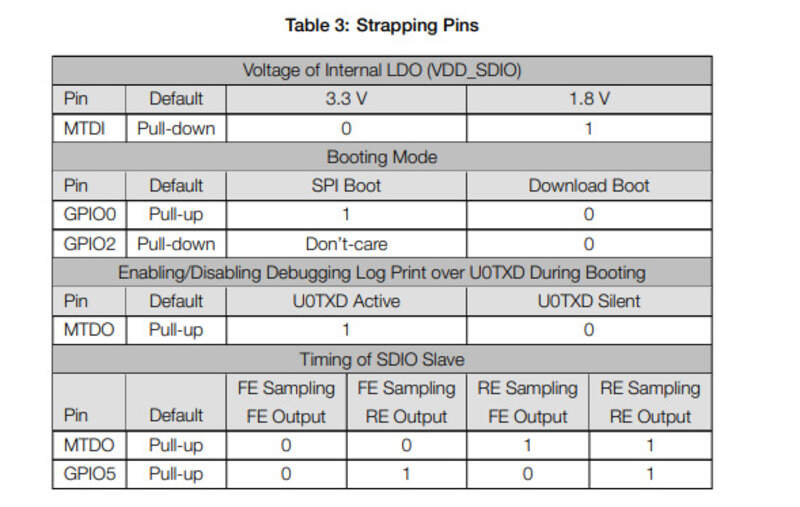
Also, the MTDO pin should be pulled up (done by default) to enable verbose, it always helps when debugging. The MTDI on the other hand should be left as is.
this is all recapped here.
Programming: in practice
Let’s connect the converter cable. If the driver is installed, it should appear in the device manager tab in Windows. You can then find the corresponding COM port.
You can see in the picture below that I’m using a 3.3V power supply so that I can monitor the current being drawn (13mA in this case) and that I’m using the converter cable.
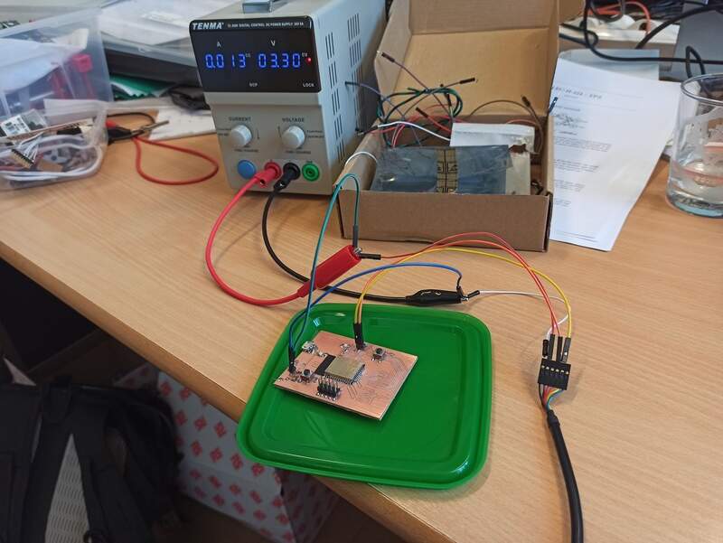
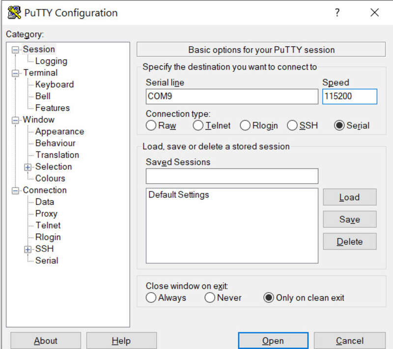
Then, let’s open a Putty terminal and select “Serial”. My cable is on COM9. Set the baud rate to 115200 as this is the UART frequency of the ESP32.
When doing the programming procedure (toggle RESET while BOOT is low), a message saying the ESP is waiting for download should appear. This indicates that the ESP is awaiting data.
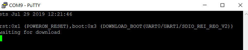
We can now feed it some code either through esptool or Arduino IDE. The “connecting” message is on the other hand saying it cannot connect to the ESP in download mode yet, so you need to perform the procedure.
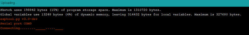
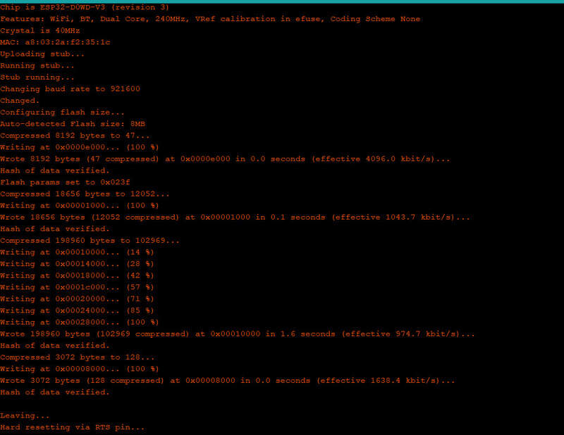
Once the procedure is done, it should immediately start transferring data.
Making a program
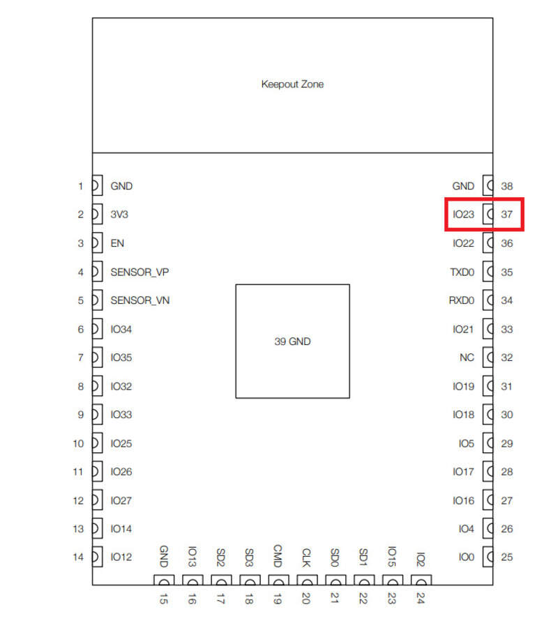
Let’s start with the basics: blinking an LED. I placed an LED on GPIO 23 (internal pin 37) with a current limiting resistor so let’s play with it and let’s also try to print something and the UART and see it on the Serial monitor !
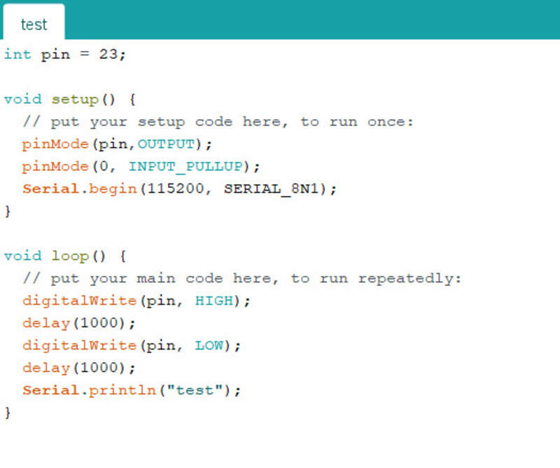
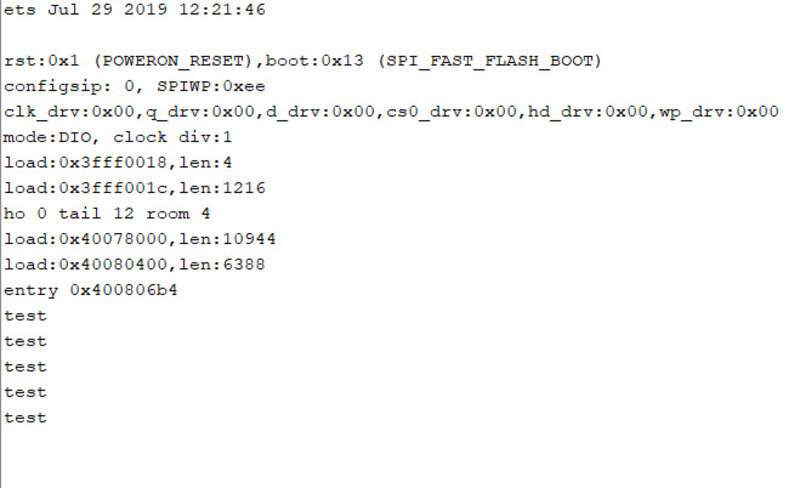
Once the programming is done, you need to press the RESET button once more to get out of the download booting mode. We can see we had a good connection after the reset and we see the “test” printouts !
The LED blinks every second.
And the current being drawn increases to 44mA as the LED is lit up.
Input and output pins
I chose my output and input pins based on their ADC channels and their capabilities (not all pins can be output nor have internal pull-ups !). However I noticed that using the Arduino’s analogRead command, the pull-ups don’t work at all as even approaching my finger would make the values completely erratic. I think this is because internally, the pins are linked to the ADC channels on analogRead function calls and they are obviously not pulled up or pulled-down as it would create an internal voltage divider.... I found that connecting any unused input to the ground was really the only way to avoid this behavior.
To be able to output either an analog value or a duty-cycle varying PWM, I can either use the ESP ledC functions or use the wrapper library for analogWrite (not natively installed) available here. You then need to include “AnalogWrite.h” and analogWrite() is now callable.
Input devices
I tried to measure three different things:
1. Light
Last week, Jason and I designed a small PCB with phototransistors and bias resistors to measure the amount of light reaching our PCB. I simply plugged it into the ESP and made a little code to read the values. I then decided to light my own LED on the ESP32 PCB based on the amount of light received by the smaller PCB with the phototransistors.
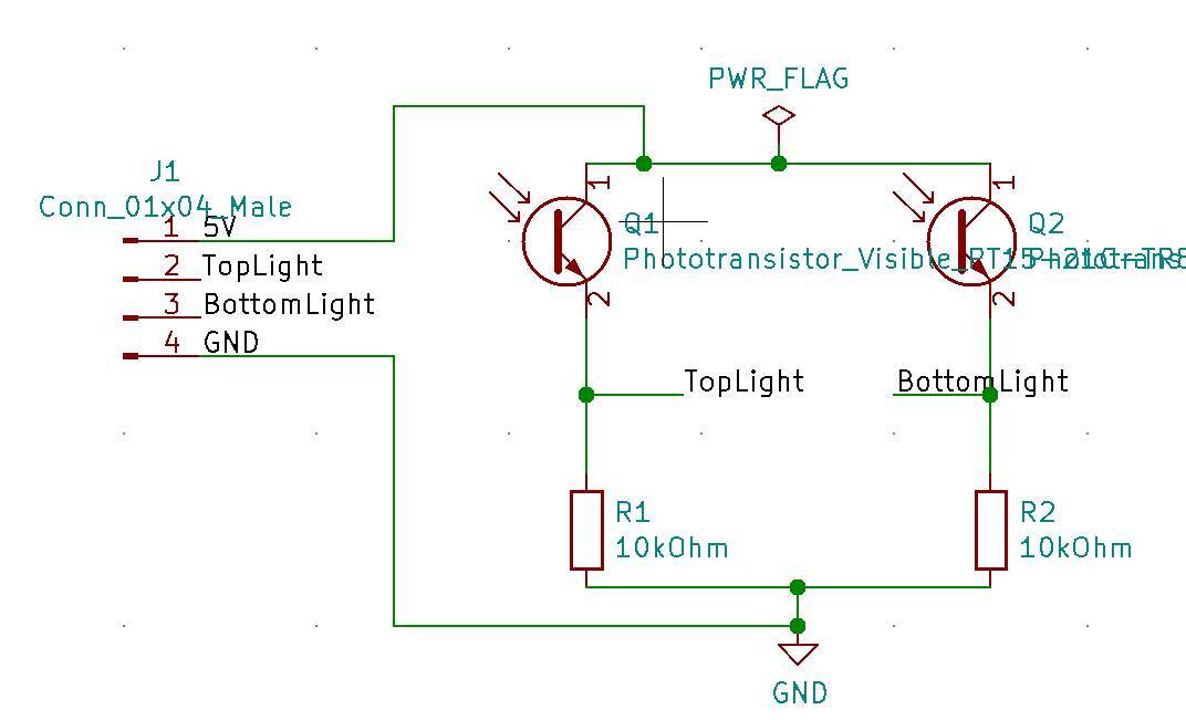
Note that we didn’t really take the time to design the correct resistor value for it but it works pretty well. What we should have done is to use the Beta value for the BJT in the datasheet, compute the maximum current flow and deduce the resistor maximum value for the output to be 3.3V max.
1 2 3 4 5 6 7 8 9 10 11 12 13 14 15 16 17 18 19 20 21 22 23 | |
The red LED on the PCB on the left will then light up based on the amount of light received as it can be seen in these videos:
With a phone lightsource (not efficient as its frequency range is too limited for the phototransistors used).
With natural light (much more efficient):
We can also see the data received whenever I move my hand to draw shadows on the PCB.
2. Strain
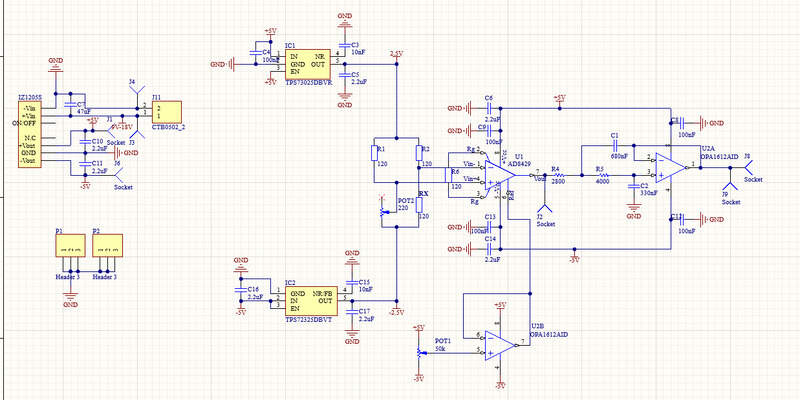
I designed a circuit to measure the strain and the deformation. Unfortunately, I had no SMD components at hand so I did it on a breadboard but it works! It seems complex but is quite simple. It is made of:
- A strain gauge, i.e. a resistance that varies with the strain
- A Wheatstone bridge to transform this resistance variation in a voltage
- A differential amplifier at the output of the Wheatstone bridge with a gain of about 100.
- A Sallen-key topology low-pass filter.
The whole acquisition chain is powered by 12V initially which becomes +5V and -5V with an IZ1205S DCDC converter. Then I use two LDO’s to reach +2.5V and -2.5V (MCP1702 and LM337).
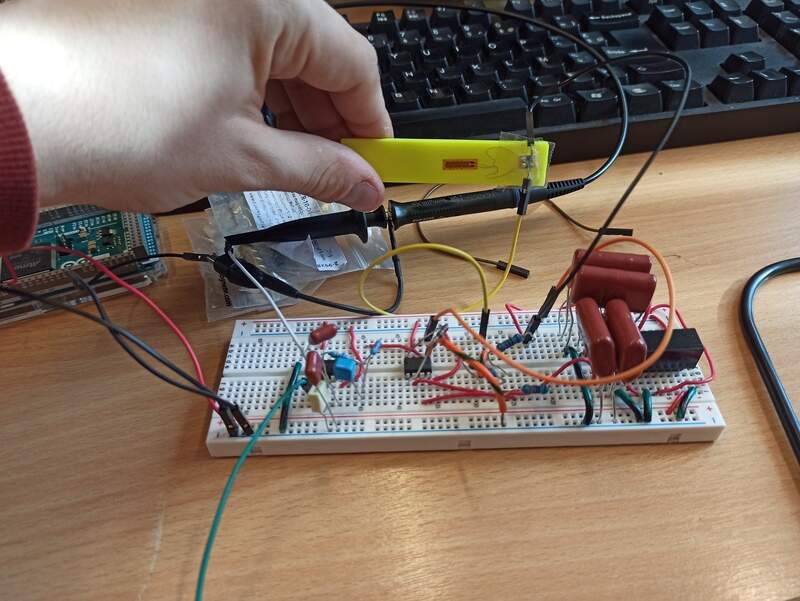
I could then see the output after the filter and also make the LED light up based on the strain:
UPDATE: I re-did almost the same circuit but on a PCB and with SMD component this time for the final project: see here.
3. Hall effect
Finally, the ESP32 also features a built-in hall effect sensor ! I just had to use the hallRead() function to be able to read the value and light up the LED based on this value:
1 2 3 4 5 6 7 8 9 10 11 12 13 14 15 16 17 18 19 20 21 22 23 24 | |
My design files
The Arduino code is available here: My Design files The ESP32 board design has been discussed in week 8.