15. Wildcard Week
Objectives
- Demonstrate workflows used in a chosen process.
- Select and apply suitable materials and processes to do your assignment.
Microfluidics
This week I chose to investigate microfluidics. I had no other idea, and there were no specific machines at the lab that weren’t used in another assignment (though I would have loved to use a waterjet cutter to improve the Urumbu machine for example).
Microfluidics is something I encountered by reading several papers about soft robotics. The idea is to precisely control and manipulate fluids, at a very small scale where surface forces dominate volumetric forces.
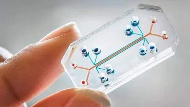
It can be extremely complex so during this week I will simply try to make a few very small microfluidic channels and let the liquid flow through them. Ideally, there should be some inlet reservoirs where the liquid will stay before flowing through the channel but I can also inject it using a syringe.
The idea is to find “easy” ways to make microfluidic devices.
My ideas
There are several ways to make microfluidics. I thought about using a laser cutter or a CNC to cut very small channels in plexiglass. If using the laser cutter, I think it would be best to voluntarily put it out of focus but I did not have the time to try it out.
I investigated two other ways that I will describe here:
Plexiglass and parafinne
My first idea is to use thin slides of plexiglass with drilled holes in one of them and place a small layer of paraffine film in between with a specific cutout for the channels.
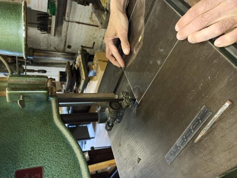
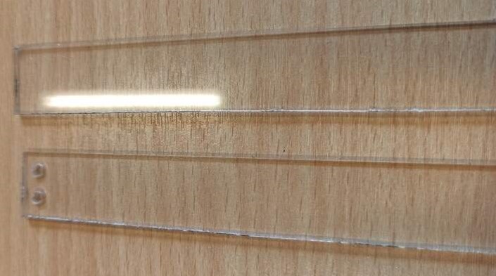
I took some plexiglass laying around and cut it in rectangular shape:
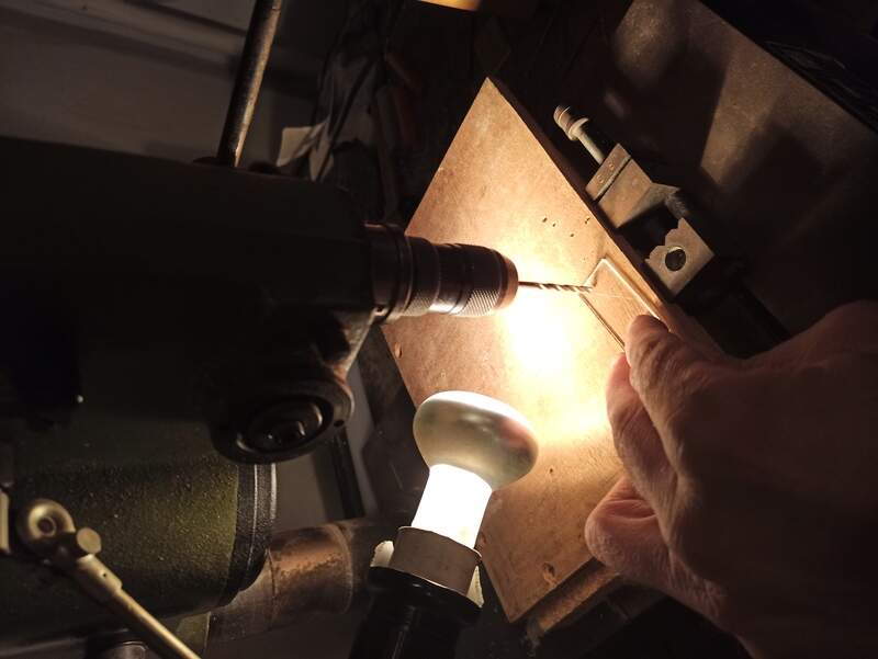
And drilled the inlet holes:
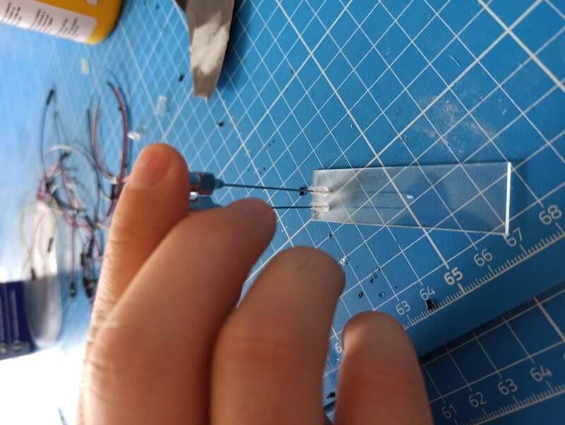
I then tried to add some plastic parts that I could use to fill water:
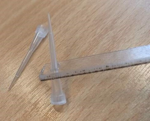
But I did not have strong glue so actually, it did not hold up well over time.
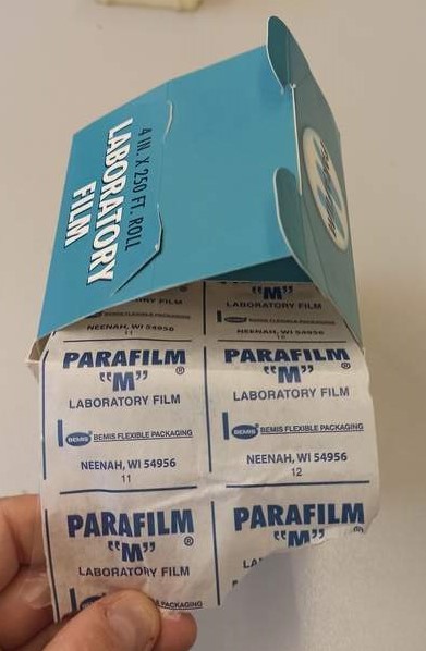
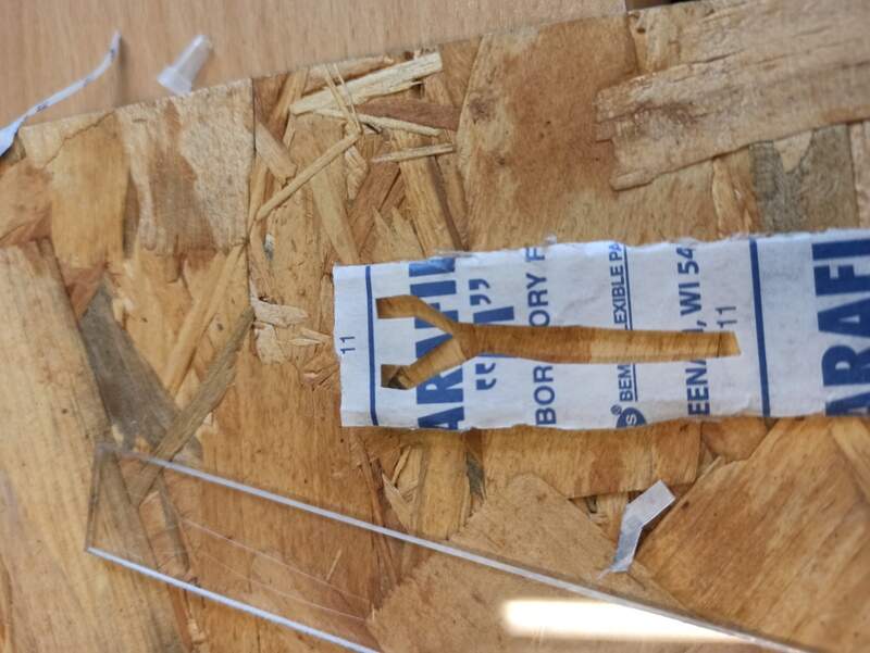
Then I cut some parafinne films that I found in the lab and placed in on the first plexiglass slide:
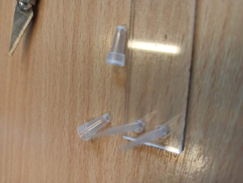
I then realized the plastic parts were not strong enough so I tried several things:
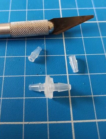
Using dedicated fluidic connectors and using a syringe to hold them in place while pouring Ecoflex 0035 fast silicone.
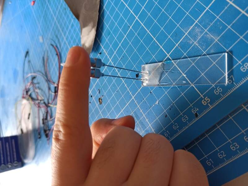
It was better but still not perfect. An epoxy glue would be, I guess, the best solution but again, I did not have superglue or epoxyglue at hand… But I did have UV-curing glue !
It was still not perfect in terms of holding but at least I tried!
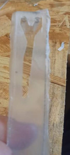
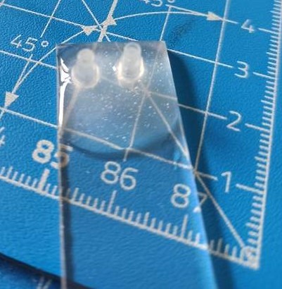
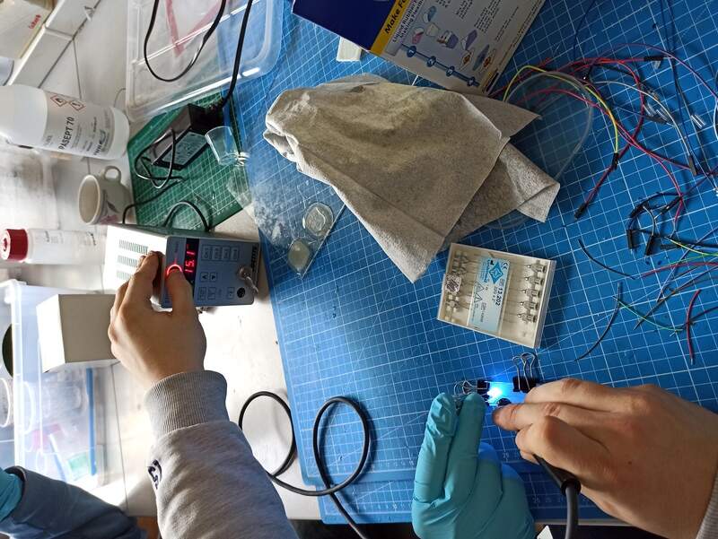
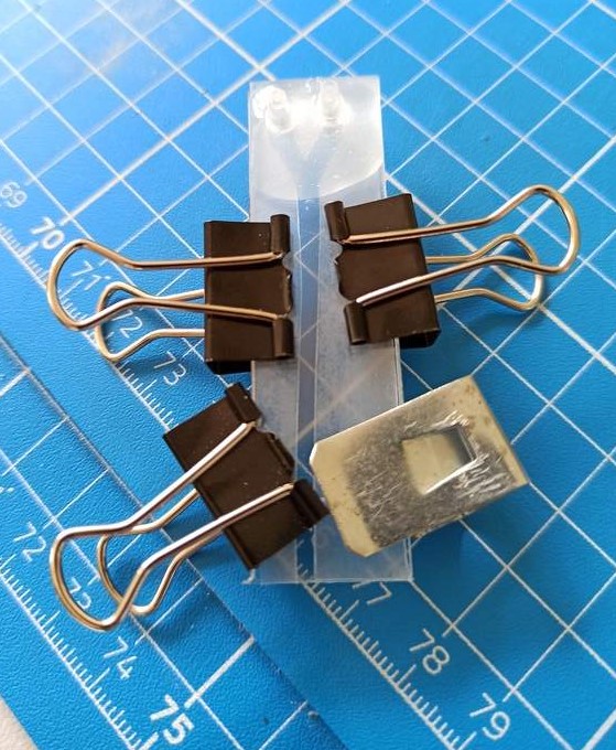
I then placed the second plate, attached it and tried to heat the parafinne up a bit to make an adhesion between the two slides.
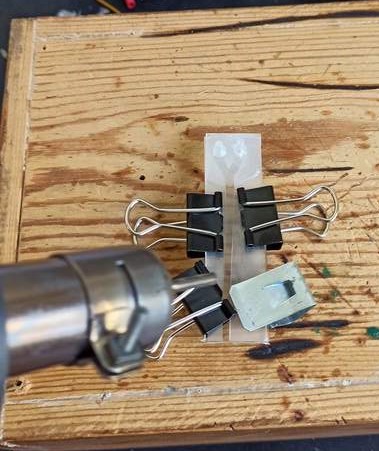
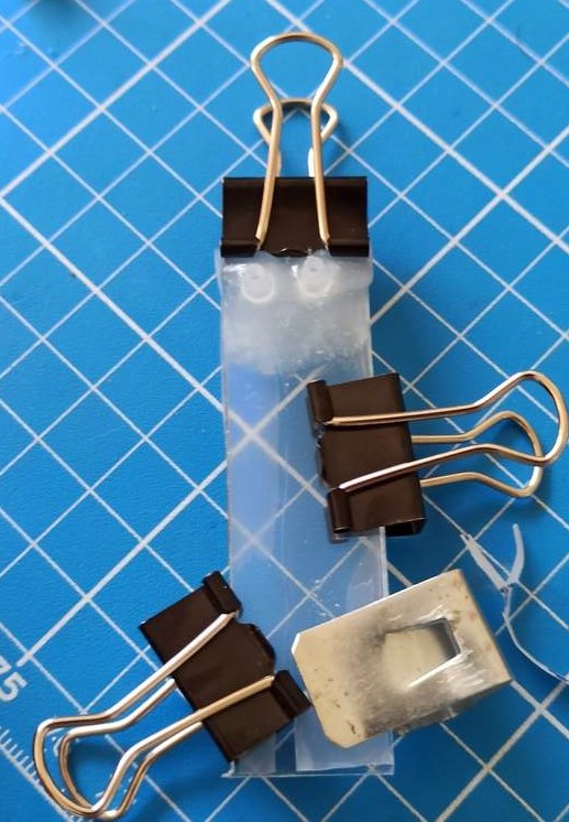
You can notice the parafinne becoming more transparent as it heats up !
Before trying it out I wanted to add some color to the water to make it more visible but the color for silicone I usually use is not miscible in water…
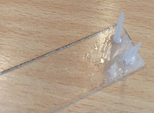
Final result:
The connectors still didn’t hold up enough time for me to get a good video and therefore some water spills out of the device. Anyway, we can see a bit of water flowing through the very basic channel. Moreover, since it is not perfectly sealed at the top, the air is flowing and the water will not flow through the channel by itself as it should. So… Far from perfect, but with very few materials you can have a microfluidic chip.
Moreover, the biggest added value of this technique is, I think, the fact that you don’t have to mill in the plexiglass and so the output result should be perfectly transparent and perfectly visible even with a microscope while the output of a laser cutter or a CNC is not perfectly smooth and can hinder the view under a microscope.
Possible improvements and solutions
For holding the plastic connectors, epoxy glue would be the best choice. Also, connectors with a large flat surface at their bottom would be ideal. I think that heating on a medium-heat plate would yield better results. One could cut the paraffine channels with a vinyl cutter!
3D-printed mold and silicone
The second solution I thought about was designing a mold in 3D and then print it at a very high resolution, allowing for very small channels, and mold a silicone on it, before sealing it on a plexiglass slide.
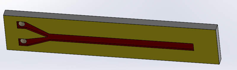
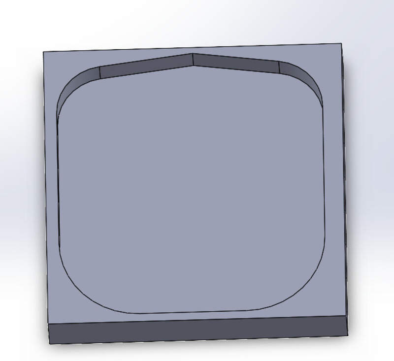
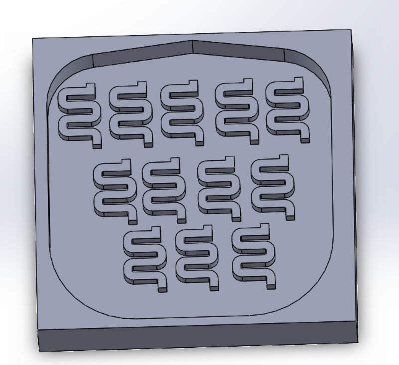
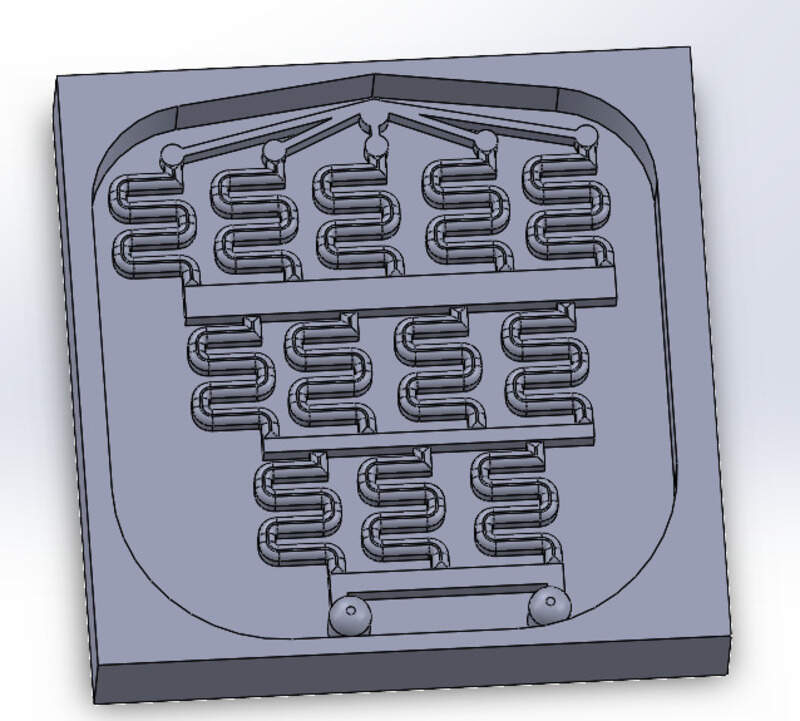
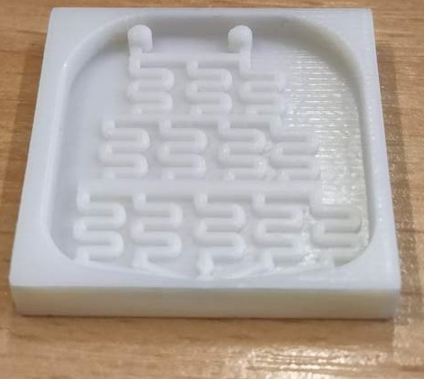
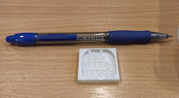
I first made the design in Solidworks. The design is quite simple: a basic rectangle of 4mm, an extrusion of 2mm to hold the silicone, a few channels (made by extruding lines) that I made as a “block” in Solidworks to make it more parametric and easy to copy-paste and here we go. The channels are 1mm high and 0.8mm wide.
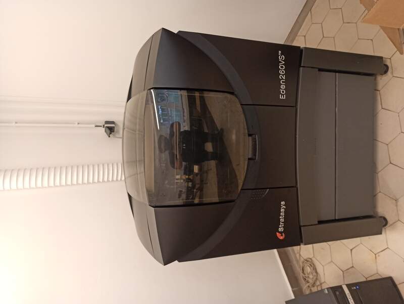
I then printed the mold with the Stratasys Eden260VS printer. A very-high resolution printer. I think it could easily work with a cheap resin printer but I don’t have one so I couldn’t try that.
The Eden is a “polyJet” technology printer, able to print ultra-thin layers, smooth surfaces and thin walls. A wide variety of materials are available. Contrary to “classical” 3D printers that I used in the 3D-printing week that use FDM (fused deposition modeling) technology, it is almost impossible to make bridges with this technology but since it is possible to use multiple materials, the support can be soluble. I chose to use it to be sure I’ll have a high enough resolution for my micro fluidic application.
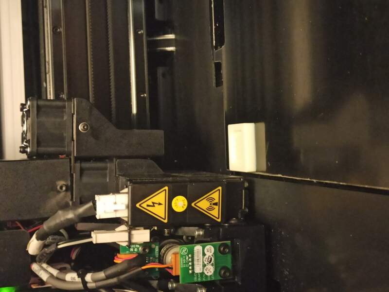
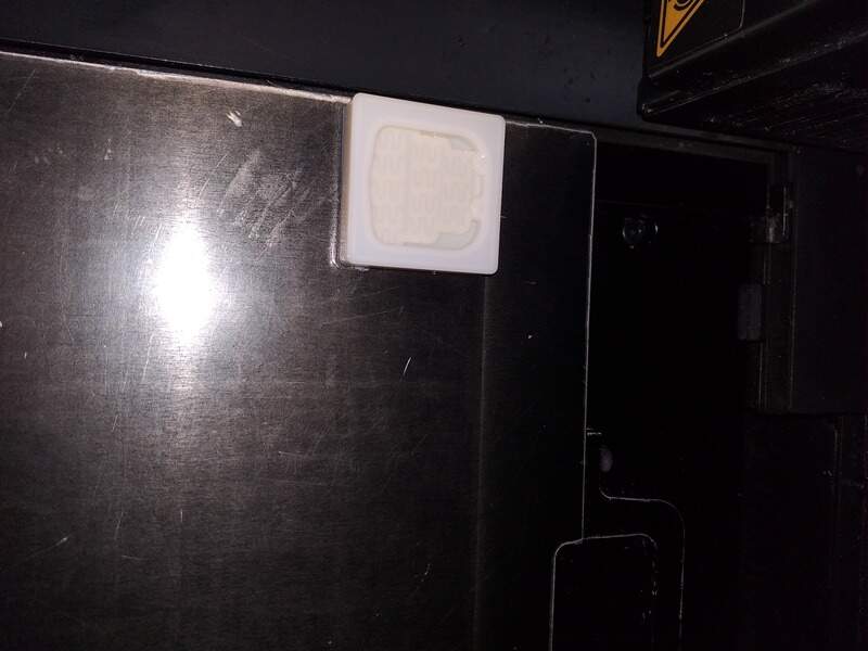
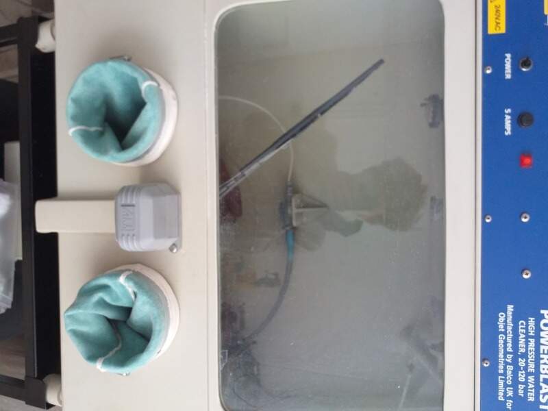
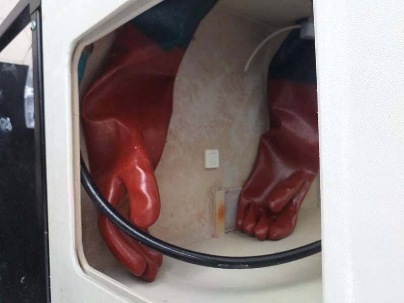
The final print comes with a bit of support on top that you can remove with first, a blast of water:
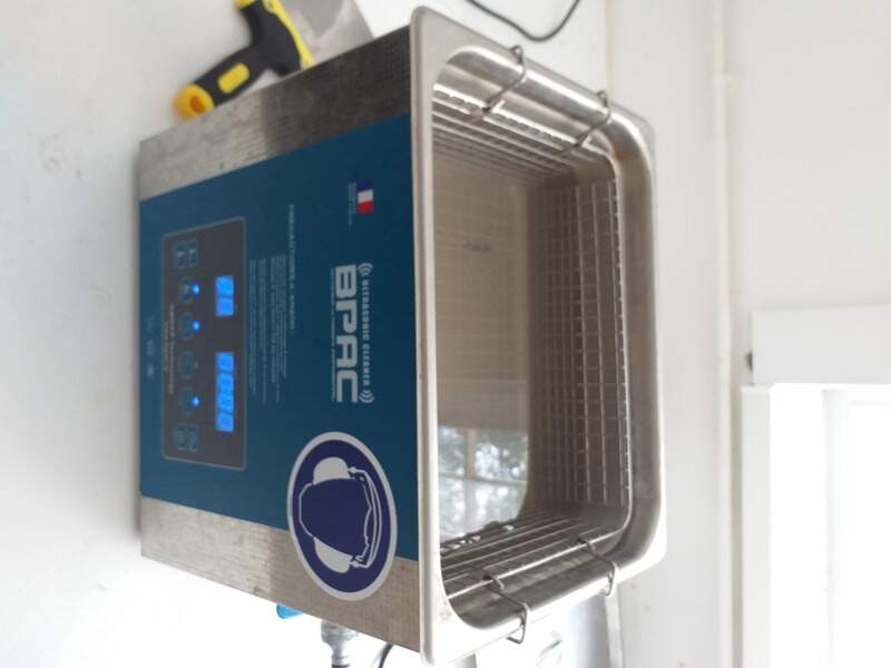
And then an ultrasonic bath of Sodium hydroxide:
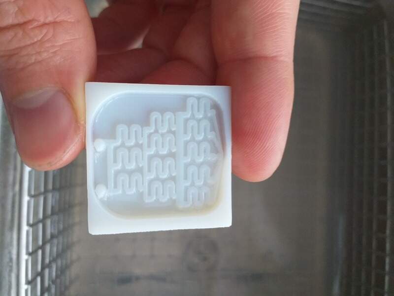
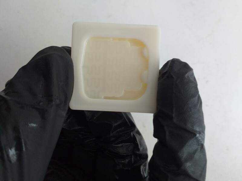
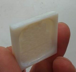
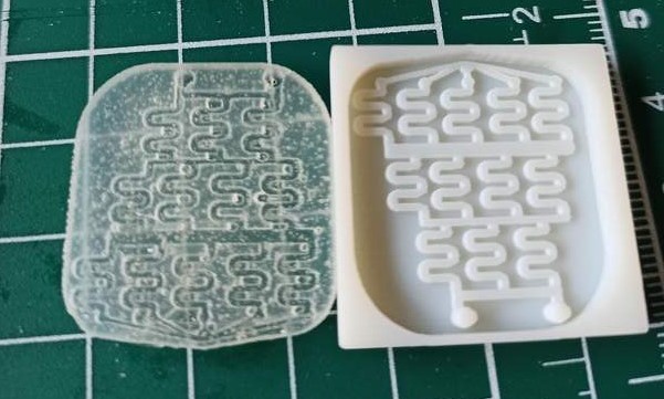
The output mold is very good !
Then I could start pouring some silicone on it. First, I used Ecoflex 0035 FAST to make some first tests:
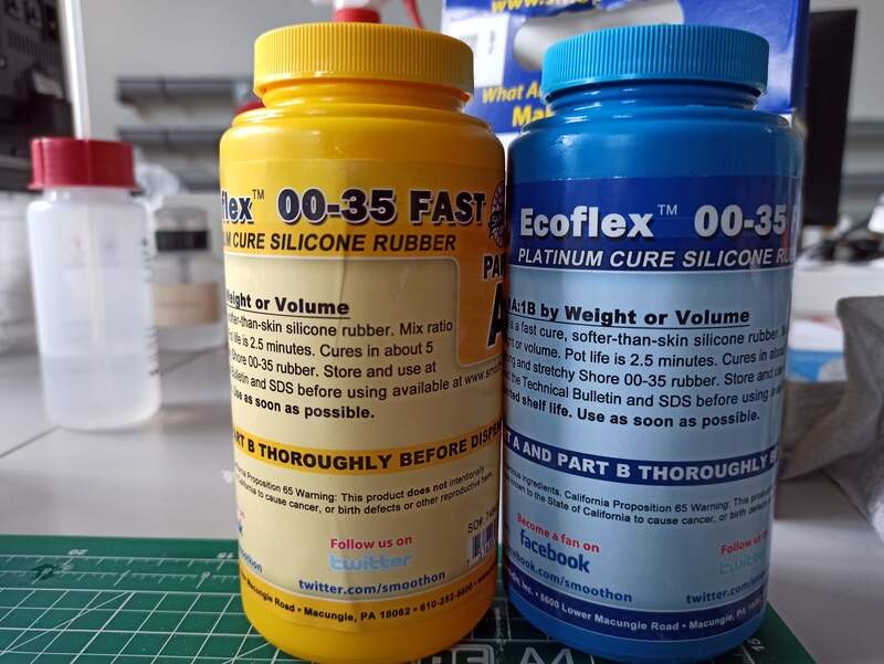
There are obviously some bubbles as the 5 min cure time does not allow any degassing. I then prepared a mold of PDMS for the next day (24h curing) but unfortunately someone at the lab touched it while curing so I had to start over but had no time so I continued using the FAST silicone.
To close the channels, I placed the silicone on the plexiglass sheat and sealed it using more ecoflex FAST.
I prepared some colored water using menthol and grenadine syrups (the grenadine one was a bit too clear though).
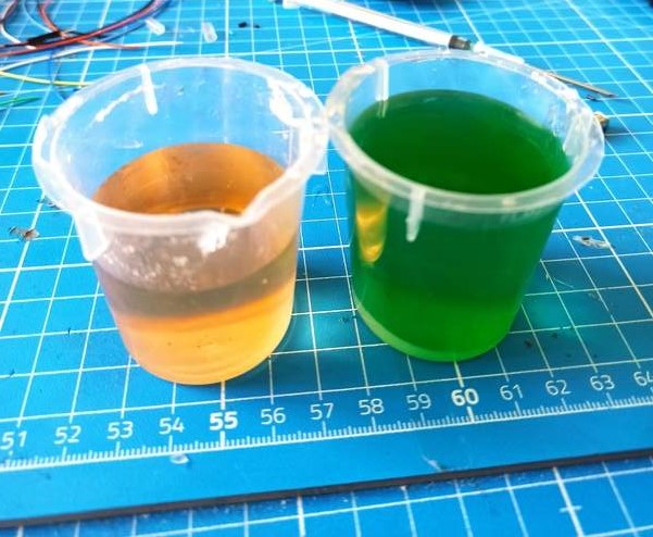
And tried to insert some water using syringes. I wanted to test how the fluids would combine but it was hard to record a video, press on the syringe and hold everything together !
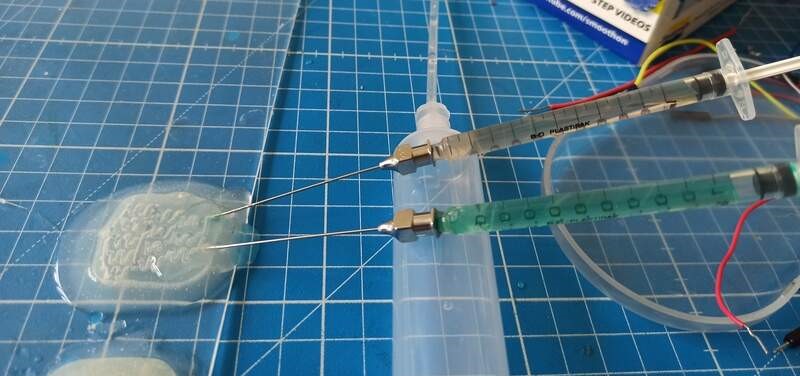
It did not yield great results so I switched to only demonstrating how the water flows through the channels.
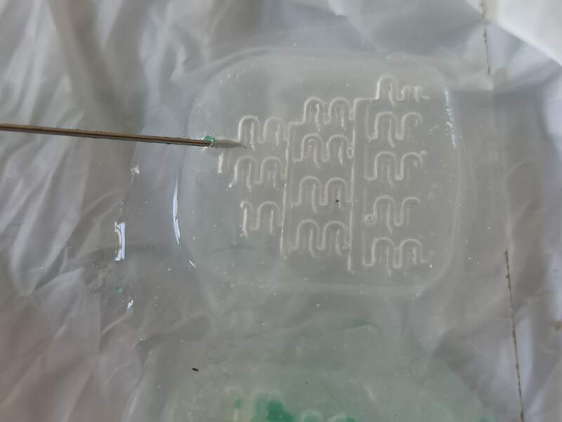
Also, sometimes I would pierce through the channels and simply inflate the whole device
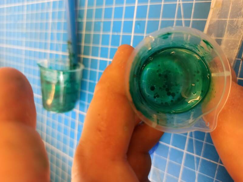
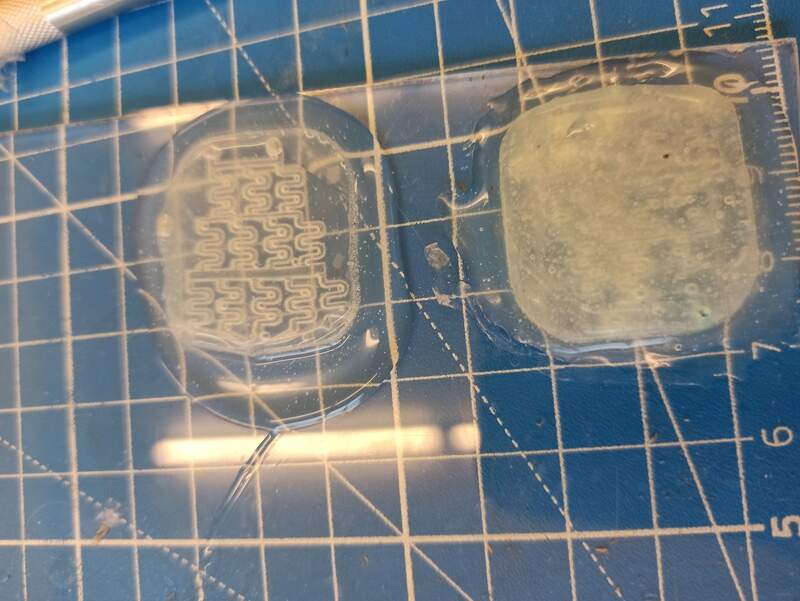
With a bit of practice I could obtain this result:
We can clearly see the water follows the least resistance path and flowing in the surrounding channels to reach the output. This is because paths that do not lead to a hole will contain air that will be compressed by the liquid and so it will not be able to go through it easily, preferring the path of least resistance, i.e. containing the hole. This demonstrates the feasibility to create microfluidic devices using 3D-printed molds and some silicone, that, more or less, is capable of “path-finding”. That could be used to find leakages for example !
Bonus: these videos shows how the fluid usually goes straight to the hole.
Possible improvements
To obtain a perfectly transparent and without any bubbles, I would recommend using Sylgard 184 PDMS (at least 24h of cure time).