Electronic Production
milling and stuffing the PCB
Intro.
Welcome to my four week of Fabacademy. This week is of Electronic Production. In this week I will going learn about PCB's making through milling process and make programmer board. since in past I used breadboard and general purpose PCB often in my hobby projects so I am excite to do and learn PCB making.
Week Task:
Group assignment: characterize the design rules for your PCB production processIndividual assignment: make an in-circuit programmer by milling and stuffing the PCB, test it, then optionally try other PCB processes
Group assignment: summary
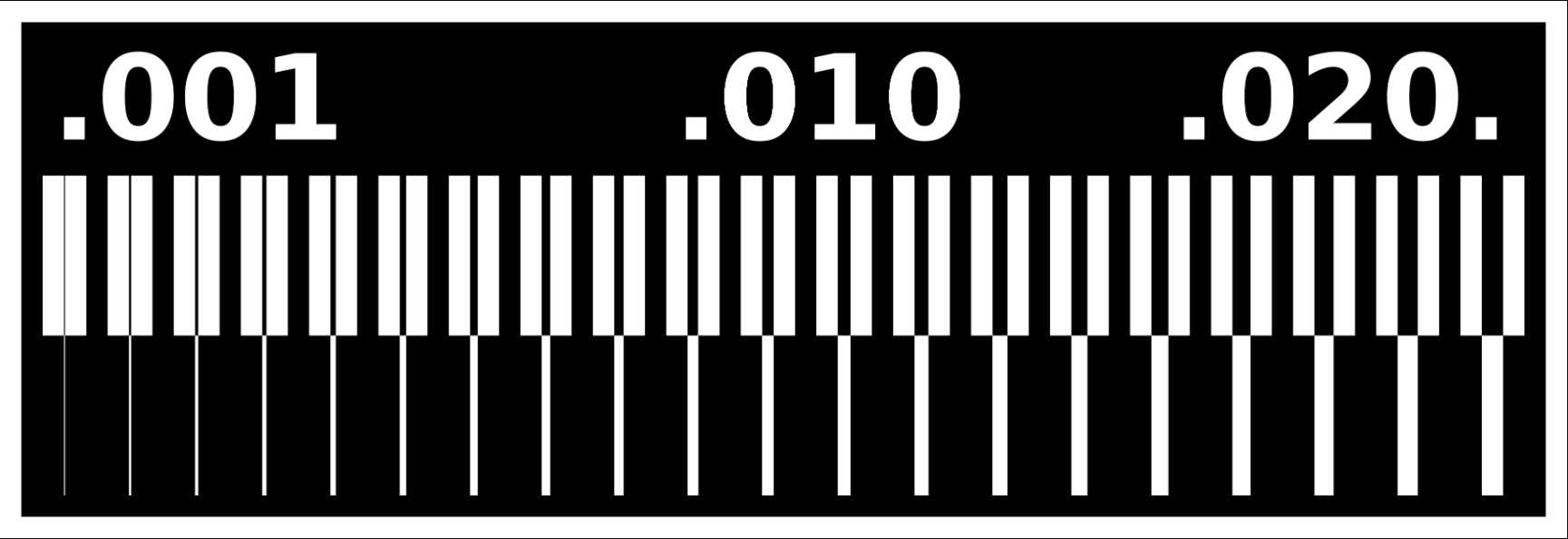
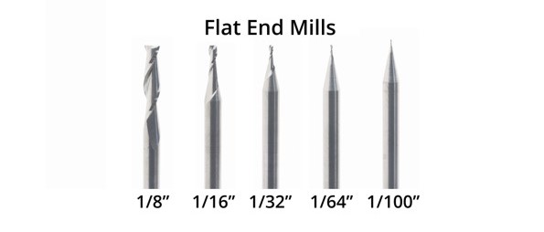
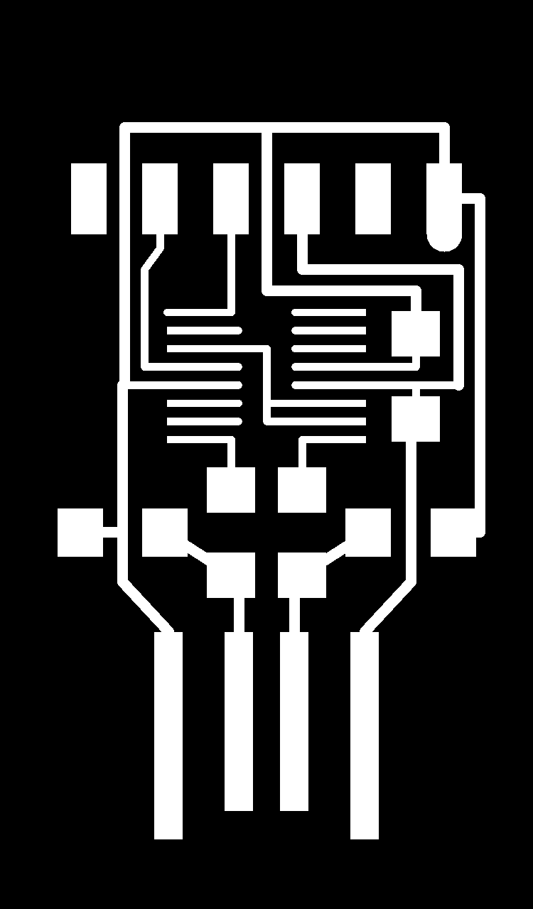
As you see on first image that there are lines differs in width. This Image we used for tracing
pattern on PCB
for testing purpose to Understand working of SRM 20 milling machine. We have used 1/64 inches
diameter bit for tracing and 1/32
inches bit for cutting out board.
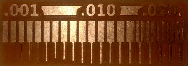
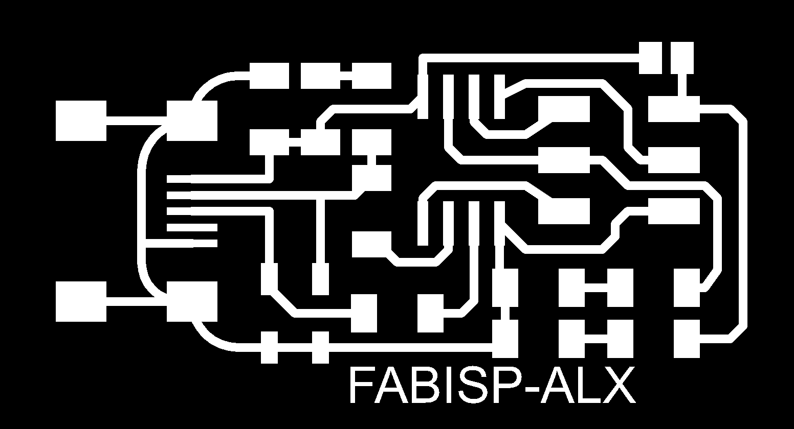
As you see on Second image which is our milling output It clearly show that machine have not trace
the lines
having width less than diameter of bit i.e 1/64 inches.
click here to know more...
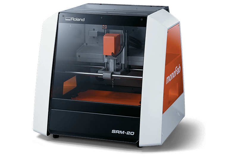
SRM 20
This is Kind of subtractive milling machine and Useful for many thing. Here in this week we used this for pcb millings by using Flat End mills
Individual assignments
Here in PCB production I going to replicated design for MCU programmers and Mill my own boards and assemble them to make it work. Here I will use milling process and blank single sided pcb to mill on circuit design
ISP (In-System programming):
So I took design and Reference from Alex Tocagon - Fabacademy 2018. I choose this board to fine my soldering skill also.

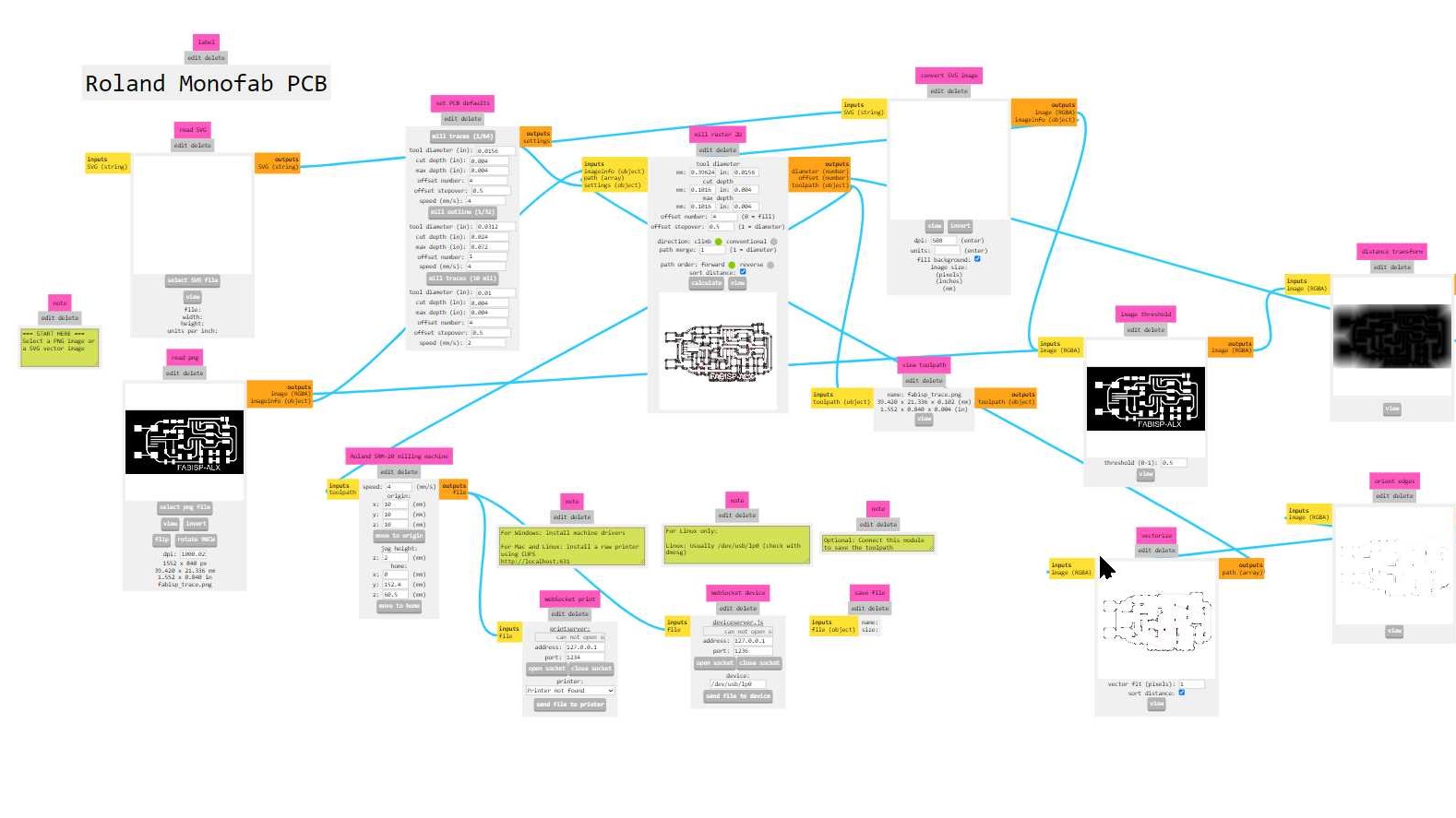
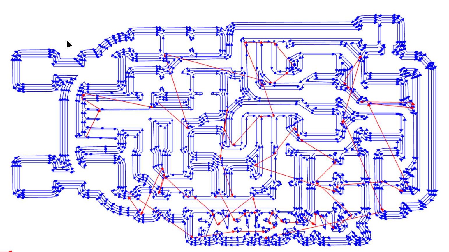
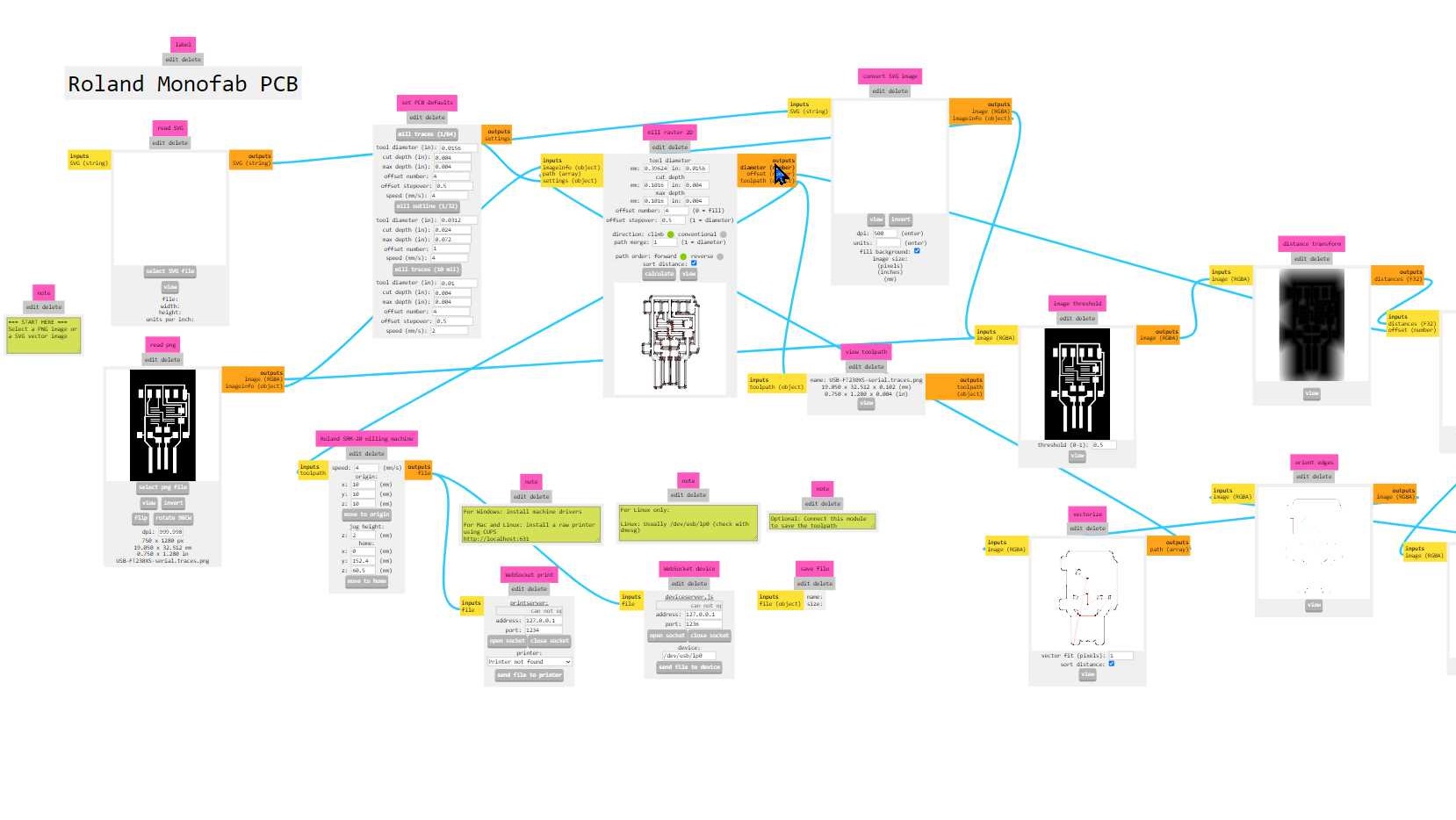
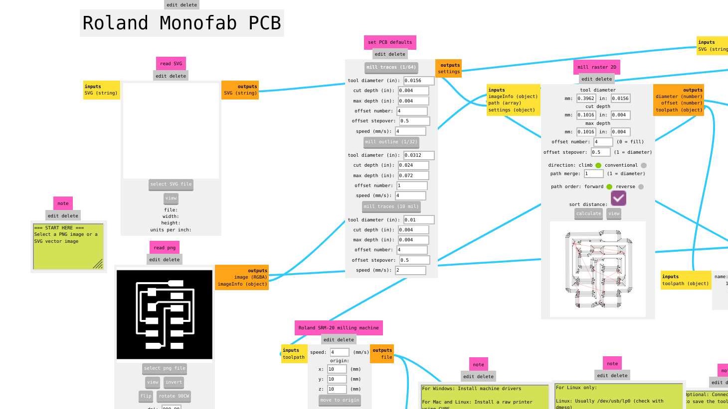
I used mods application in my linux system to generate paths and to communicate with SRM 20 for PCB
milling process.
mods is a modular cross platform tool for
fablabs.
It is based on independent but interrelated modules. mods could potentially be used for CAD,
CAM, machine control, automation, building UI, read input devices, react to to physical models,
and much more.
List of Components
- 1 x ATtiny45 or ATtiny85
- 2 x 1 kΩ resistors
- 2 x 499Ω resistors
- 2 x 49Ω resistors
- 2 x 3.3v Zener diodes
- 1 x red LED
- 1 x green LED
- 1 x 100nF capacitor
- 1 x pins of 2x3 pins
Before and After Soldering the Component on our FabISP PCB
.jpg)
.jpg)
Yeah! Done well :)
Installing avr gcc toolchain
On Ubuntu terminal use given command and thats all
sudo apt-get install gcc-avr binutils-avr gdb-avr avr-libc avrdude
For window 10 os you need to install gitbash first then
Next follow the steps given on link
download and extract firmware - Alex Tocagon
Open GitBash and Change directory using cd command to folder you extracted the firmware
Run make command wait till it get done. you can find .hex file in folder
next connect our FabISP programmer with pre-build programmer to program it using SPI. I am going to use USBasp programmer. Since in window 10 os you may need to install driver first.
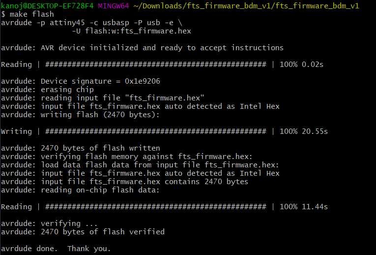
Once everythings get done well use following commands and steps to load firmware in our programmer using gitbash and before that make sure wire connection between pre-made USBasp and made FabISP
.jpg)
1.make flash
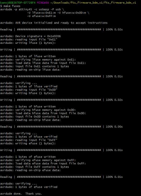
2.make fuses
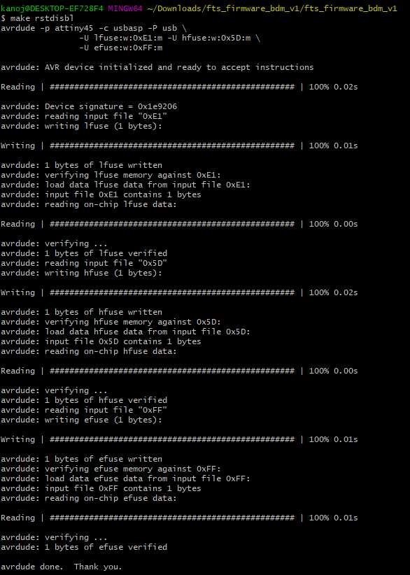
3.make rstdisbl
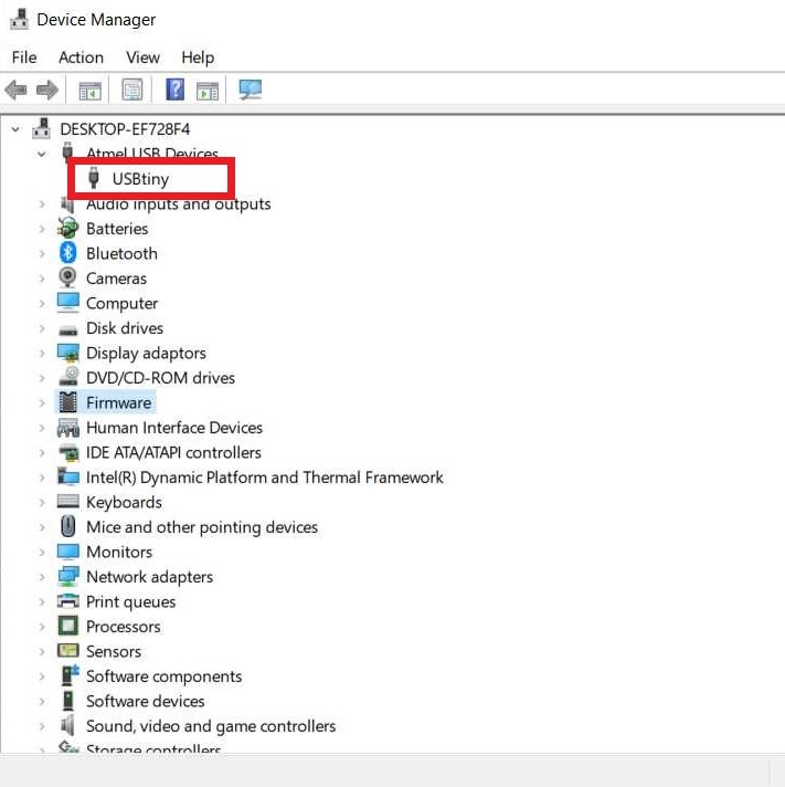
Once steps get done. Disconnect everythings and connect our Fabisb through usb using micro usb connector wire and check device manager on your Window 10 system. It will detect as a UsbTiny since we have already installed driver from adafruit
.jpg)
yeah! If you happy and you know clap your hands....
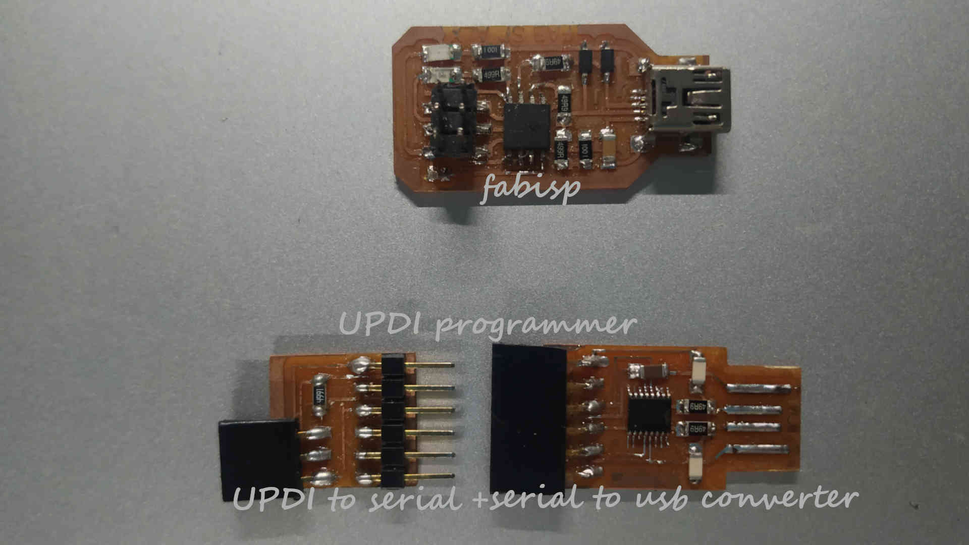
UPDI (Unified Program and Debug Interface):
I took design and Reference from Adrián Torres -fabacademy 2020. I choose to do this to learn about programmer programming using different interface
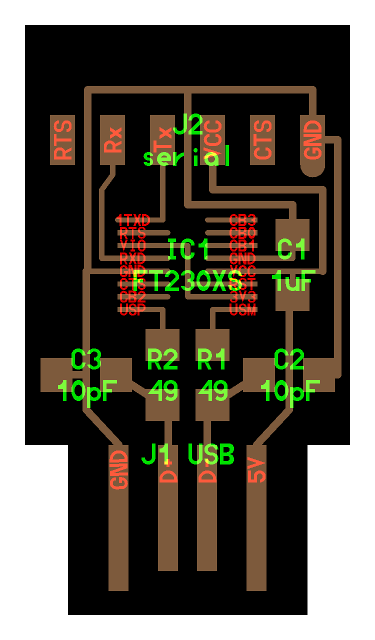
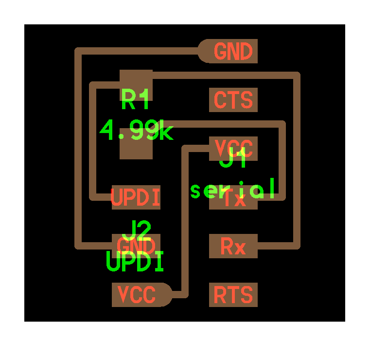
Here you can see there are two boards in programmer. One the big one is normal FTDI board which is use as a usb to serial converter and second board is a extension that convert it into UPDI programmer. This programmer use one wire to program chips since other two are VCC and GND. There is no need of loading firmware to making it work, solder components properly and it is ready to use
FTDI board

Extension Board


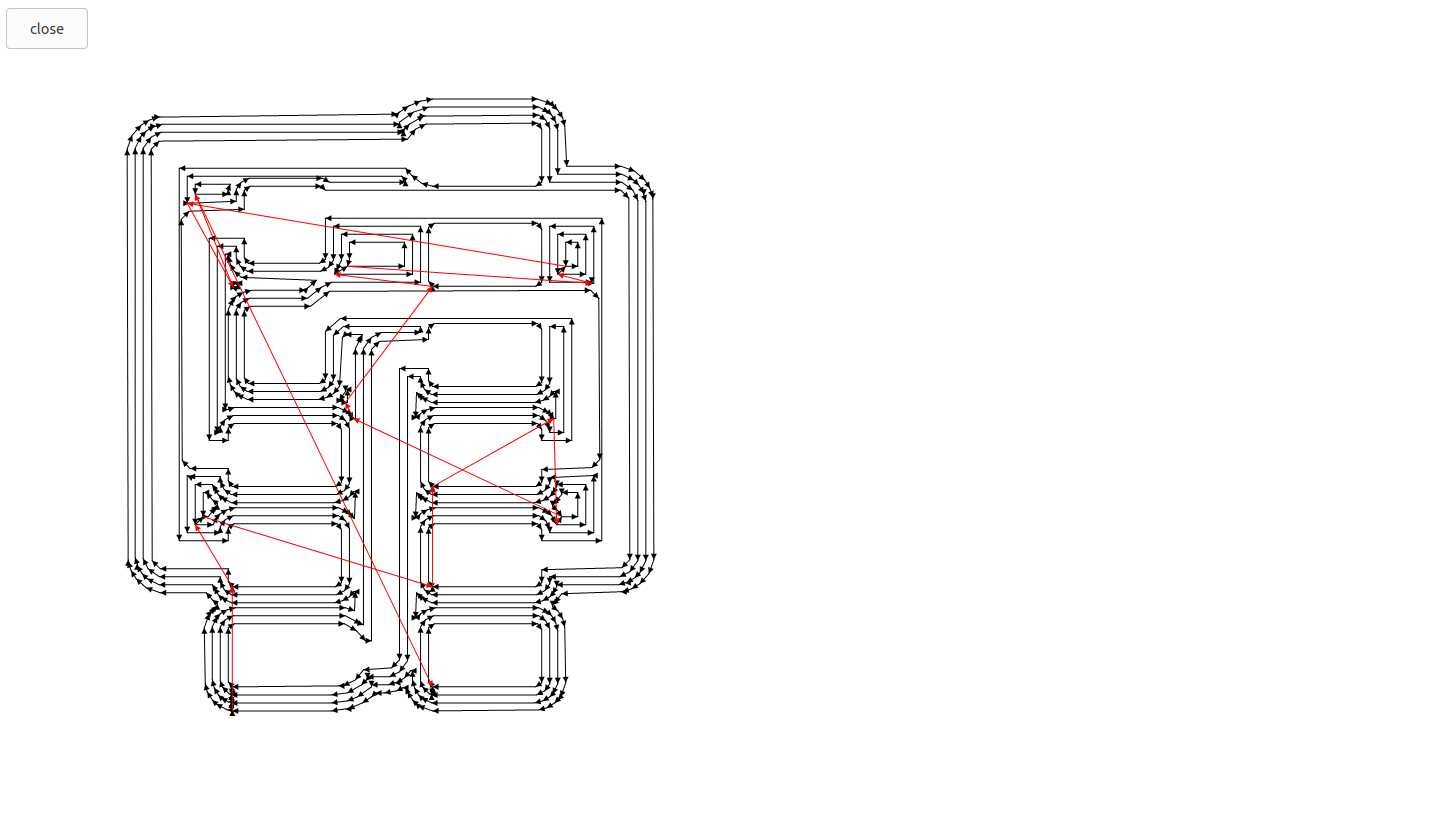
Generating path using mods

After Milling on SRM 20 milling machine
.jpg)
.jpg)
.jpg)
List of Component
FTDI Board
- FTDI FT230XS smd chip x 1
- 10pF x 2 Capacitors
- 49.9 Ohm x 2 Resistors
- 1uF x 1 Capacitors
- 1 x female header of 1x6 pins
Extension Board
- 499 Ohm x 1 Resistor
- 1 x male header of 1x6 pins
- 1 x female header of 1x3 pins
now next we have to setup arduino IDE for our updi programmer. for that follow the given steps:
- Install Arduino IDE on your system.
- Run Arduino IDE. On menu goto
File/preferences. - In Preferences on settings tap in
Additional boards manager URLpaste the given linkhttp://drazzy.com/package_drazzy.com_index.jsonclick Ok - Now again on menu goto
Tools/board/Boards Managerand search formegaTinyCore by Spence Kondeand install it
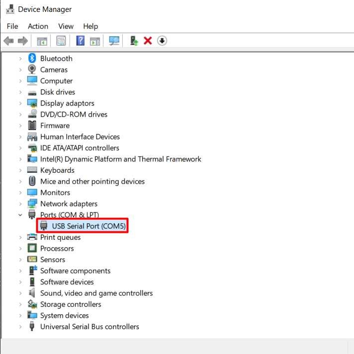
now connect the FDTI board with Extension board and connect it with your PC/laptop using USB port and Check device manager to make sure board is working.
.jpg)
.jpg)
.jpg)
Next follow the given steps
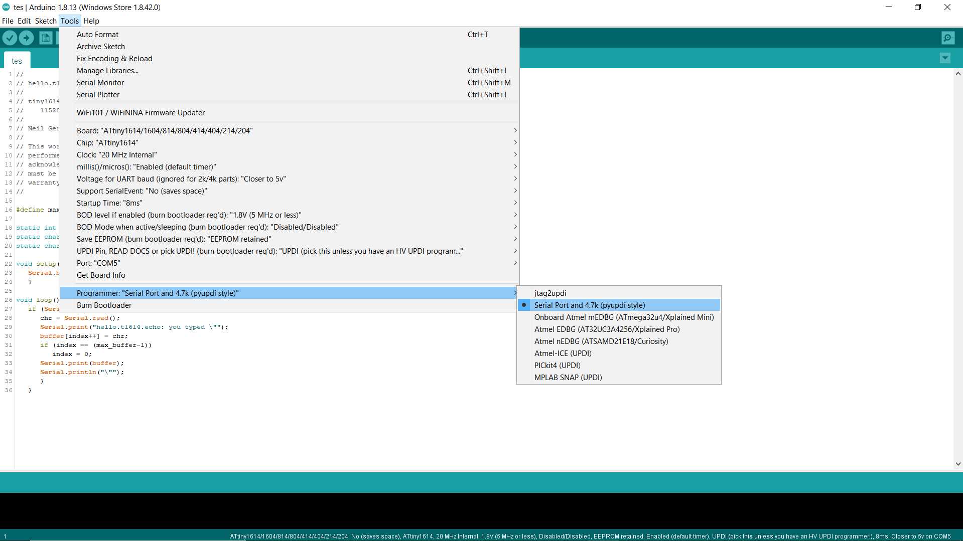
- Run Arduino IDE and On menu goto
Tools/board/megaTinyCore/and Select chip you wanted to program (I have used pre-made hello board that have attiny1614 on it, joined extra wire for VCC as you see on last image) - Next Select
Port(mostly it auto select the correct port but it can be done manually also) - Next in same Tools menu goto
Programmerand SelectSerial Port and 4.7k (pyupdi style) programmer - Write code (I took pre-made code for attiny1614 for testing out board ) Verify it and Upload it
*copy given code for attiny1614 for test purpose - ref
//
// hello.t1614.echo.ino
//
// tiny1614 echo hello-world
//    115200 baud
//
// Neil Gershenfeld 12/22/19
//
// This work may be reproduced, modified, distributed,
// performed, and displayed for any purpose, but must
// acknowledge this project. Copyright is retained and
// must be preserved. The work is provided as is; no
// warranty is provided, and users accept all liability.
//

#define max_buffer 25

static int index = 0;
static char chr;
static char buffer[max_buffer] = {0};

void setup() {
   Serial.begin(115200);
   }

void loop() {
   if (Serial.available() > 0) {
      chr = Serial.read();
      Serial.print("hello.t1614.echo: you typed \"");
      buffer[index++] = chr;
      if (index == (max_buffer-1))
         index = 0;
      Serial.print(buffer);
      Serial.println("\"");
      }
   }
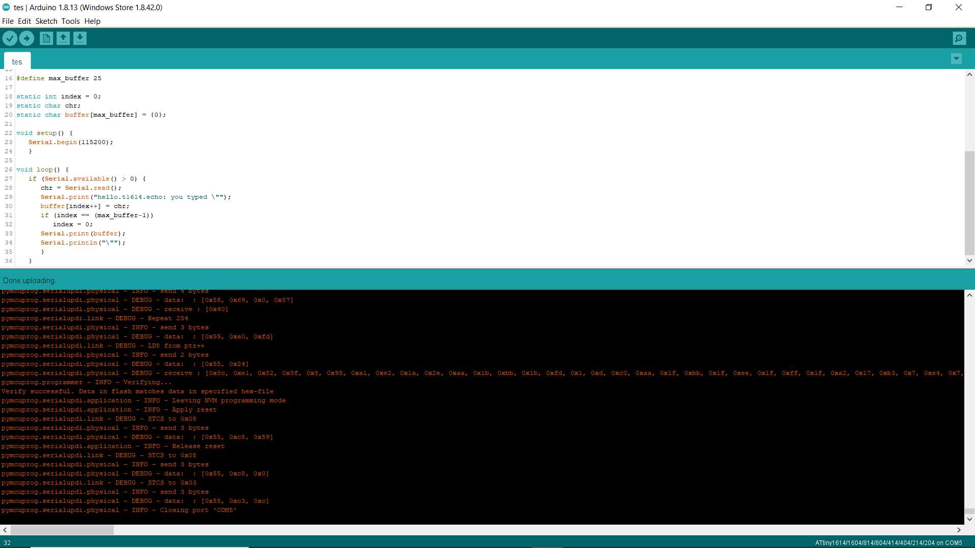
Hurrey! It done uploading.
Learning Outcomes:
This week in electronic production I first time made PCB with no big mistake and errors. I like the idea of milling pcb not etching it with hazardous chemicals. since even milling process give out harmful dust safety is much. Making of own programmer was nice experience for me. Fabisp is similar to what I used to use in my project before. UPDI programmer is the complete new thing I learned in this week assignment