Computer Controlled Cutting
You do not always need a machine to make something beautiful.
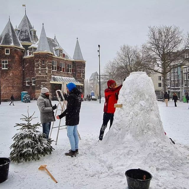
this week has been very cold and snowy. This made attending the lab hard for some as public transport was halted.But we also had a lot of fun with the snow and ice
Description
This week we try the first machines. We learn about lasers and knifes and how they can cut materials. We learn how to make designs press-fit for these machines, how to operate and how to maintain and clean them.
Assignments
| # | Assignment | Fin |
|---|---|---|
| 1 | Demonstrate and describe parametric 2D modelling processes | 1 |
| 2 | Identify and explain processes involved in using the laser cutter. | 1 |
| 3 | Develop, evaluate and construct the parametric construction kit | 1 |
| 4 | Identify and explain processes involved in using the vinyl cutter. | 1 |
Spirals - Have you?
| Spirals | Description | Done |
|---|---|---|
| A | characterized your lasercutter's focus, power, speed, rate, kerf, and joint clearance | x |
| B | Explained how you parametrically designed your files | 1 |
| C | Documented how you made your press-fit kit | 1 |
| D | Documented how you made your vinyl cutting | 1 |
| E | Included your original design files | - |
| F | Included your hero shots | 1 |
Assignment #1 - Group assignment.
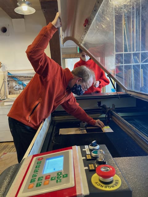
This is how the big laser machine works.
Laser
Hardware
We have a BRM laser; a Dutch laser in name and company, but all chinese parts. It was bought just as BRM stopped producing it as it became affordable then. The driver, ancient maddriving software, was replaced by Henk and now the much better, easier and still supported Lightburn software can be used. This made earth a slightly better place to live on.
The machine takes up about 1/8 of the room in Waag. It has a giant lid that you NEED TO OPEN AND CLOSE WITH TWO HANDS otherwise it says BANG and Henk looks unhappy.
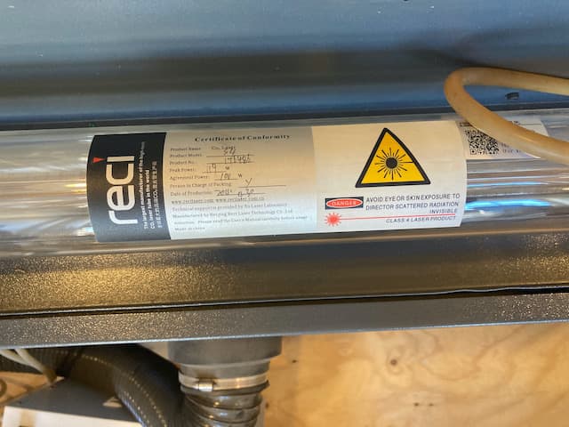
There is a big laser in the back of the machine. It is cooled with water. The laser travels over three mirrors to the cutting bed. It is focused manually.
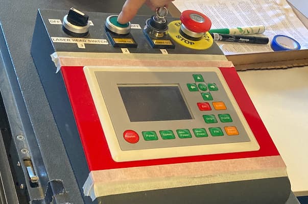
There are three main buttons, a screen and a number of smaller buttons on the interface.
Next to the BRM laser there is a venting machine that sucks away the fumes. NOTE Do not forget to turn this air-sucker on before cutting. Also it is wise to keep it running a little after you finished your cutting job so it can suck away remaining smoke.
The laser head
The laser head has four main parts.
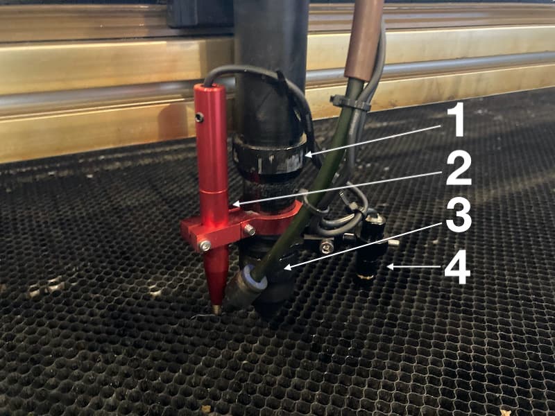
- Focus-adjust. This is a ring that loosens if you turn it. If it is loose, you can move the laser-lens up and down. This way you can change focus.
- Auto-focus. This is a future feature. If Henk has time, he plans to use this part to measure distance to the material and have the laser auto-focus.
- The is the air-vent. It blows on fresh cool air on the part where the cutting is taking place. This way small particles are blown away and the material is cooled directly after is has been cut.
- Red-dot. This is also a future feature. It is a little red lamp pointing where the laser will cut. This way you can better predict where cutting will happen on your material.
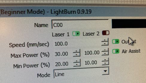
Software
The windows machine has the software Lightburn on it, which can also be used to make quick drawing and make small modifications to your files just before printing.
But most important you need it to set power and speed.
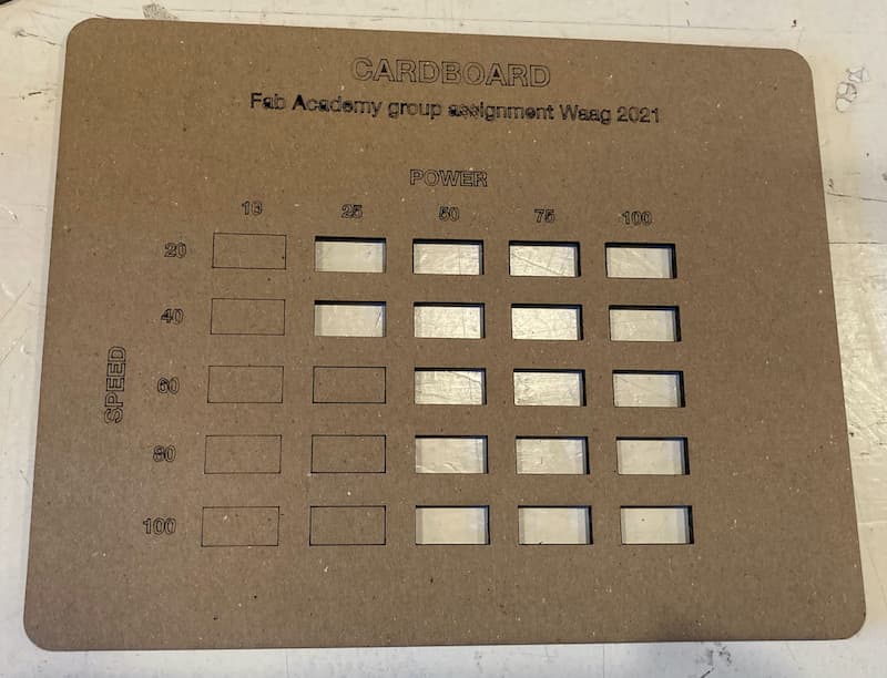
We did an initial play with power and speed on carton and produced this:
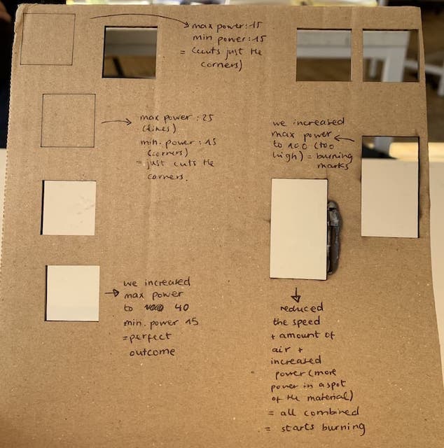
It is a nice first overview how you can play with the setting.
NOTE: In general a good rule of thumb is that you want to set the speed and power as low as possible to achieve what you want to do
This makes for - Nice clean cuts: no smokey, smelly burns. - Smooth corners.
Of course, the downside is that the job takes longer to finish. So this is a good rule of thumb when timing is not an issue.
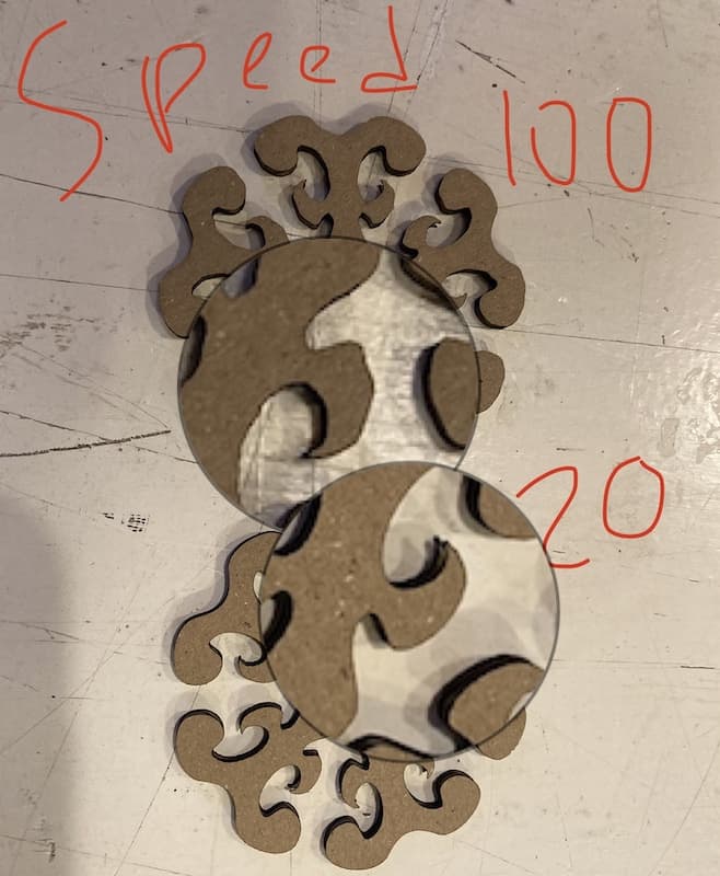
The last thing you can see in this comparison of speed:
Later we did a better, more systemic, test of the laser power and speed interplay and produced a handy reference board to check before you start cutting. We did this very several materials. Do note that the headers are the same as we did not change the names of the board because of time pressure.
Carton
Kerf
Kerf is the part of the material that is blown/cut/burned away because of the cutting operation. Yuo need to adjust for Kerf if you want to make something that is snap-fit. The part of the material you loose, needs to be added back to your design because otherwise stuff don't snap.
In a parametric model you can easily adjust for kerf.
We calculated the kerf by cutting 9 pieces of each exactly 1cm width. We then place the cutted pieced together and measured how long the were.
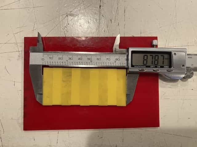
In this example you can see that the remaining material is not 9cm but only 8.787cm. That means that 0,213cm is burned away by the laser. As there are ten cuts made, we need to divide this by a factor 10. One kerf is 0,0213cm. Which is the same as 0,213mm.
Kerf for different materials.
Kerf can vary a little between materials, but the variation is so little that a good kerf measurement on one material can count for almost all other materials.
- The kerf for acrylic is 0.213
- The kerf for carton is 0,173
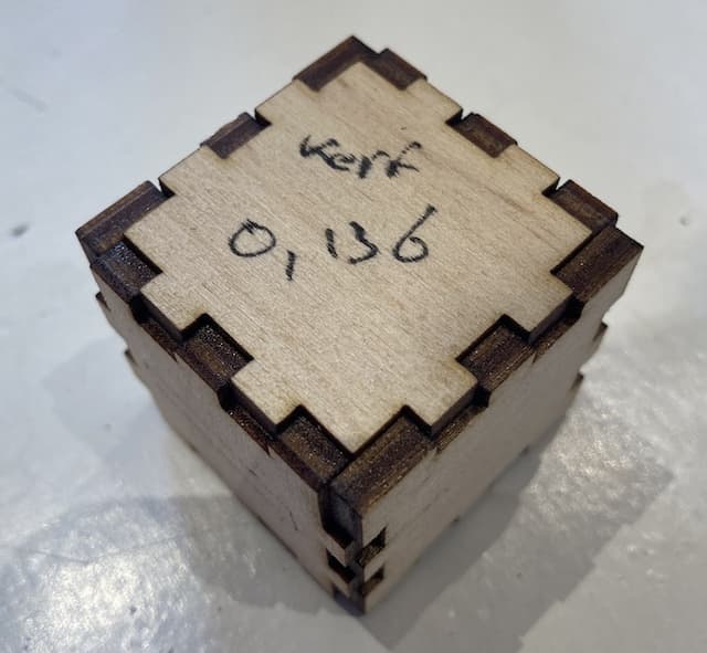
- The kerf for wood is 0.136
According to other measurements, it is save to keep 0.17 as the kerf of our BRM laser.
Snapfit
Using the kerf and the material thickness you can then calculated the thickness of your cuts that you need to make something snapfit. But there is one more variable you need to take into account; some materials bend/compress and deform easier then others. Carton can be compressed easier then acrylic. Therefor it is also wise to make a little press-fit measuring tool if you plan on making a lot of joints.
This is the press-fit measuring tool of carton
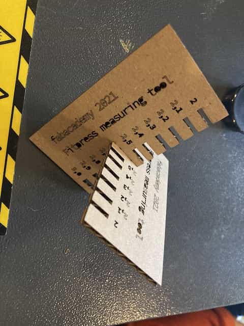
It shows that a cut of 2.6 is a good width of the gap to have it press-fit.
Stuff I learned.
- Always measure a lot. You think you got it right, but you don't.
- Explain to others what you are doing; this way your own mistakes become apparent without your listener even having to say something. A rubber duck will also do if no humans want to listen to you.
- Never turn your back on the laser. It is trying to kill itself.
- Acrylic cutting is best done in summer, when you can leave all windows open for proper ventilation.
Assignment #2 & 3 (B) - Carton playplax.
You know, for kids.
As I kid I sometimes got to play with Playplax. It was my dads memory toy, so he was very careful with it. The polystyrene parts had become brittle in de two decades in between and it easily broke. The other day I saw he had found it again, another two decades had passed, and my son was playing with it.
Its attractiveness was mostly thanks to the funky colours. Playing with it in bright sunlight had a mesmerizing effect. The building qualities were also fun, but limited. I will try to recreate it in cardboard and modify the structure so that
- it allows for more dynamic forms
- it can be painted upon and new parts can easily and very cheap be made again.
I am also considering engraving the favorite cartoon characters on the faces of the pieces to make them even more appealing to my kids.
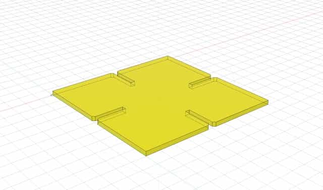
The design needs to be parametric, so I will mainly use Fusion360 to make the design. This is my first sketch. I made one hole in the side that is dependent on the material thickness.
Now I need to make the other gaps and find the relation between thickness, kerf and the width of the gap.
These are my current parameters:
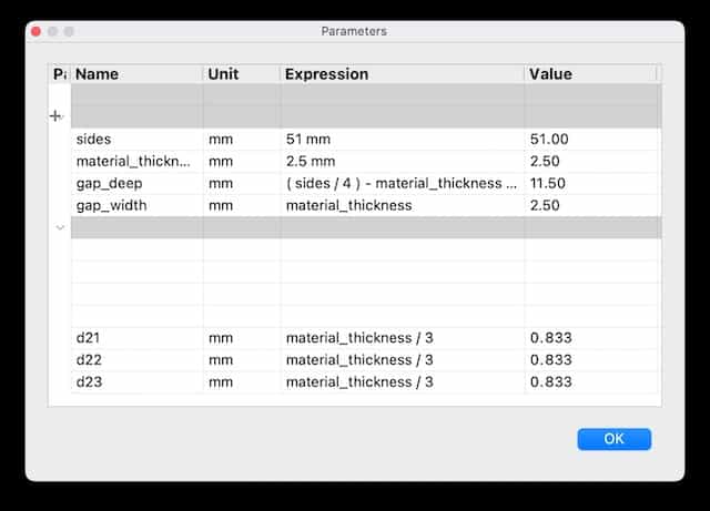
The actual doing.
I am now going to try to cut these. I want to ut them from wood. But so far we only calculated kerf and thickness for acrylic and carton. So to prevent waste I will first make it from carton.
To do the math. We calculated with the little comb that the perfect fit for carton is at 2,6 or 2,7mm. As I like it to be a bit loose, I am going to go with 2,7mmm
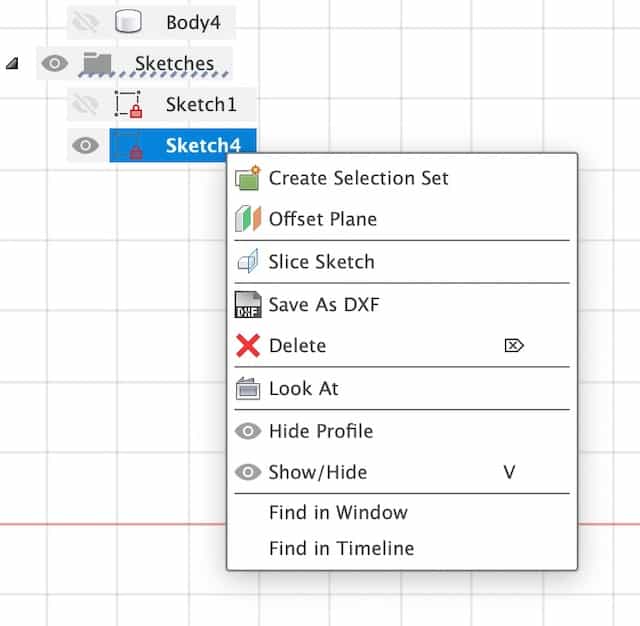
In Fusion360 I made a sketch with all the parameters. BUT. I created the chamfer after I extruded the object. The Chamfer is also parametric and related to Material Thickness. But when I export the sketch to a .dxf object, the chamfers do not get transferred. I had to create a new sketch from the top-face of the extruded body.
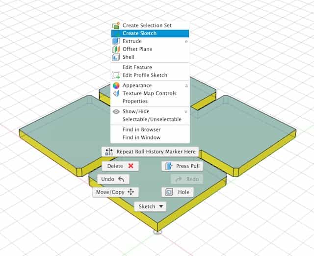
And then I export NOT FROM THE FILE MENU, but from the contextual menu of the newly created sketch. Like this:
That file I opened in deepnest, which calculated how many I can best place on a surface. This is nonsense to do, as they are squares. But still good to use the software for a moment.
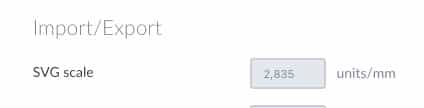
NOTE I thought my sketch was 51x51mm, but deepnest made it 18x18mm. This is because of the translation of points to mm in .svg. You can set the translation in the preferences of deepnest
I resized this in the Lightburn software, but that is not how it should be. Also the resulting object was not press-fit and way to loose.
I adjusted the gap-width (substracted the Kerf) and deepened the gap-deepness. (added a kerf twice). The result is now a press-fit design. I asked deepnest how many fit on the carton we used and the program calculated that there should be room for 216 of them.
Interesting observations during the cutting process that will effect the laser focus:
- The carton is bended; it is hard to keep it 100% flat on the cutting bed.
- The laser finds its own, optimized path. This causes parts of the carton to partly fall down on the cutting bed because of previous issue.
- In the end some parts were severely tilted.
- There is an airflow in the machine. This makes the light carton pieces wobble.
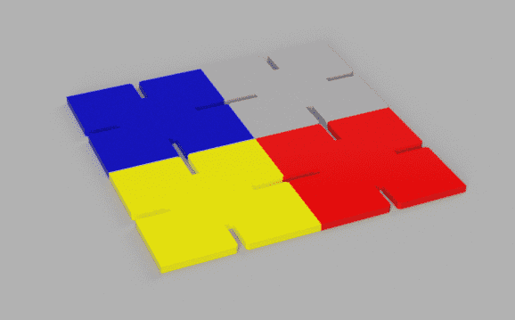
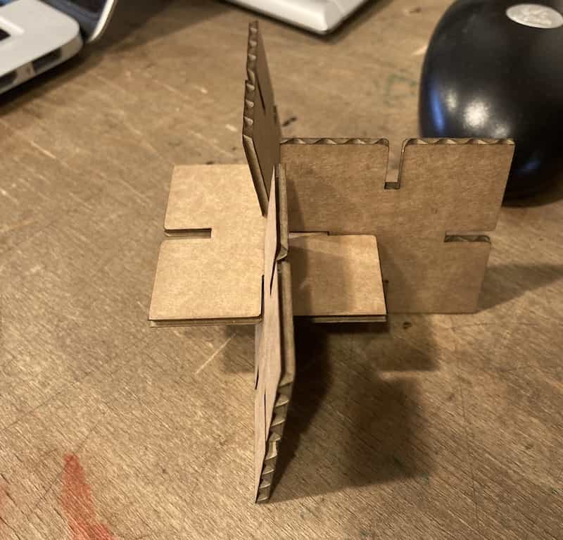
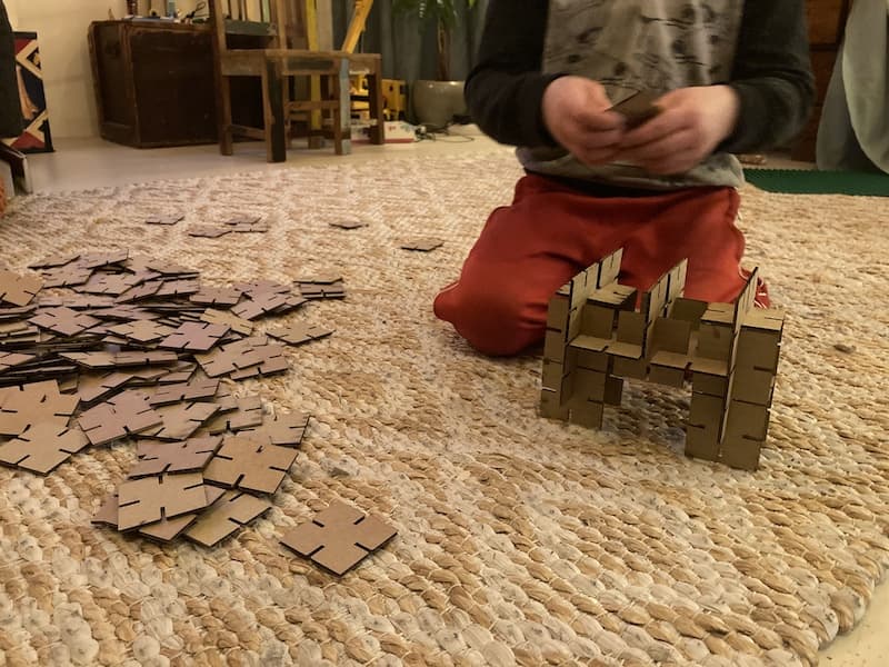
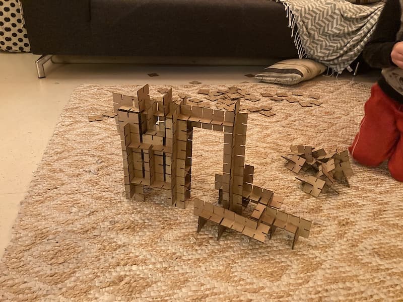
The End Result
The 216 parts fit nicely together. some fit better then others, probably because of the focus issues outlined above. When I arrived home I did the ultimate test on my kids to see if this creation had any value. It proves to be highly addictive and very inspirational. We are now three days on and it has been the only toy my kids want to play with.
Things I have learned and still want to do.
- It was a nice idea to engrave them with characters; I made two and the kids loved it. But it creates a lot of mess and it damages the sturdiness of the parts and it makes the making process about eight times as long.
- It remains to be seen how long the carton survives, but luckily it is easy, and cheap, to make new ones. Maybe next iteration should be wood.
- a box to contain the puzzles, but also fits nicely into the cupboard I have at home. Use Cuttle for this.
- The sides of the boxes should extrude a little bit on the bottom to allow for easier sliding.
Assignment 2 (B) - A cupboard
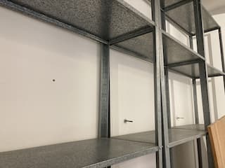
In preparation of the 'Make something big' week I played with the idea to make a cupboard. I tested making the parts of the design in Cuttle. I have this big shelve thing at home. The spaces are too big, it needs smaller shelves in order to be useful.
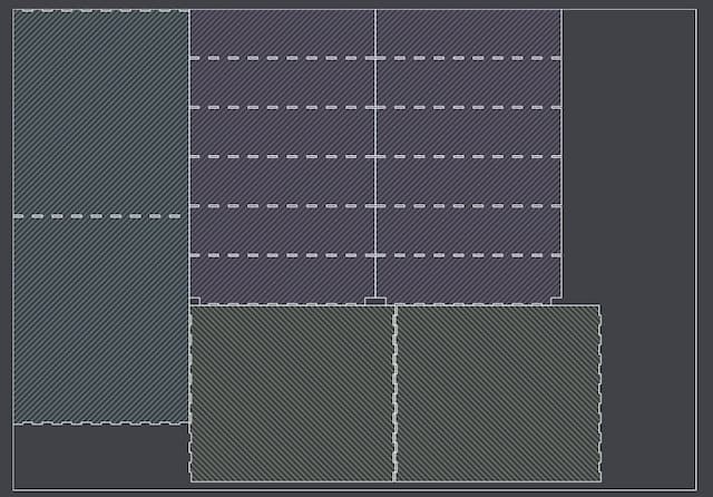
So I set of to make different parts in cuttle. Most of the sizes I made parametric.
I was struggling a lot with having the holes in the right place. Only now, when I write this, I am stupefied why I did not make it parametric as well.
I was dragging this little handle to the right position. In the right part of the screen the numerical value was changing when I was dragging.
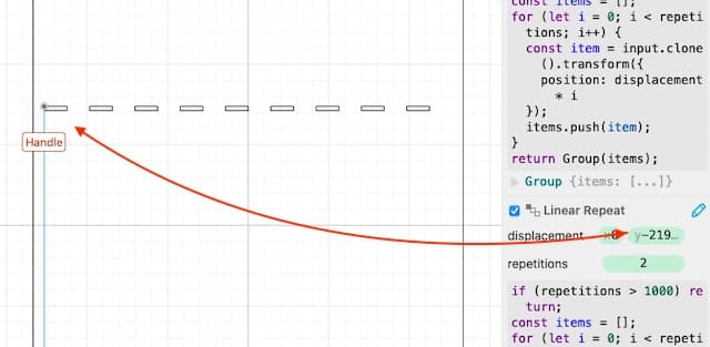
So the other way around also works. You can change the numerical value to move the handle. And then you can also add a parameter, instead of a number.
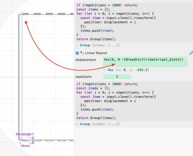
In this way I ended up with three different parts: the sides, the top and the boards. These I placed on two files with the help of deepnest.
I felt very confident and wanted to make it in wood immediately, but Henk convinced me to first make it in carton. I have probably made mistakes and carton is cheaper.
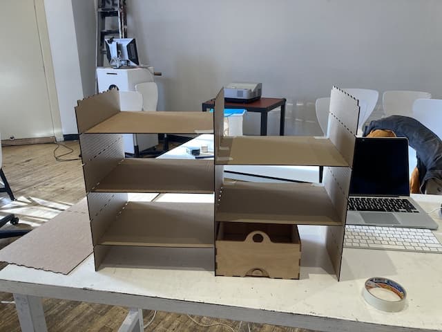
As the carton is very weak, and the object rather large it couldn't really support itself. Also finger-joints are not the best for carton; there is not enough meat to really keep stuck. But the real test came when I could put them in the shelve at home:
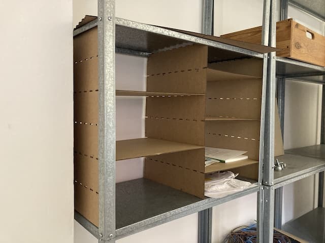
That didn't quiet fit for measuring reasons. and I made a mistake in the top part because of which it didn't fit on the standers. But I also want to make some modifications now that I have seen how it fits in real life. The shelve has little extruding side that are now in front of the parts I made. So if I want to slide drawers in, they will get stuck behind that extrusion.
Learnings:
- It is good to always make your design in a cheap material first. But the setback is that cheaper material also has different qualities.
- More calculation is needed.
- The number of fingers on the boards should be halve of the hole in the standers so that I put a board on both side of a stander and the fingers don't have to fight for the same hole.
Assignment #3 (C) - A little box.
This is a little extra assignment I did because I was unsure if the playplax pieces would pass the snap-fit test of Henk. So I made a quick box using the Make-a-Box website. This was snap-fit, so I could check that of my to-do list.
Things I have learned and still want to do.
- if you focus a lot on getting the kerf right, you might forget the material thickness.
- This learned me that you can actually play with it; it doesn't always need to be flush; maybe a little extrution on one side can make a drawer-box slide easier in-and-out of a cupboard.
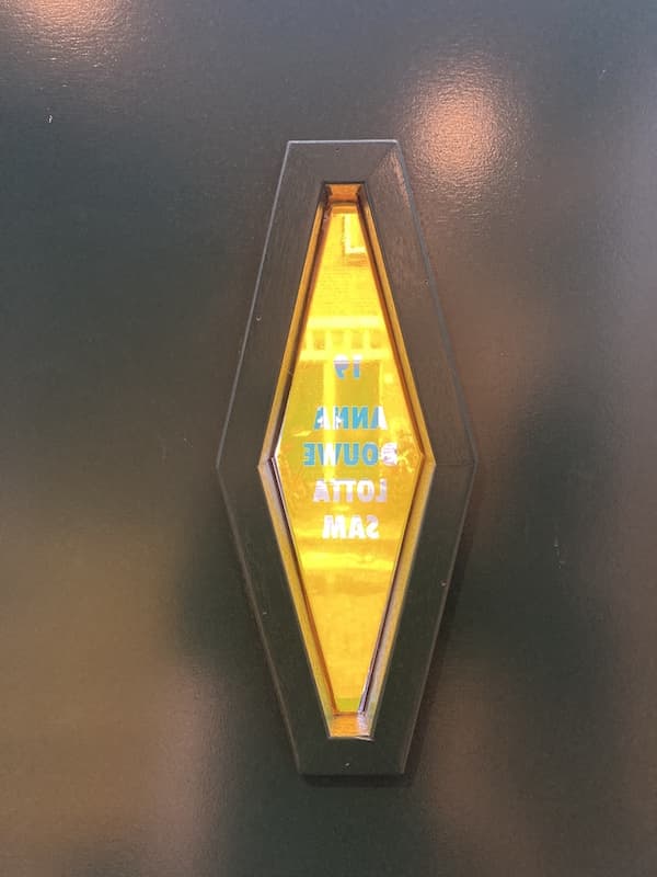
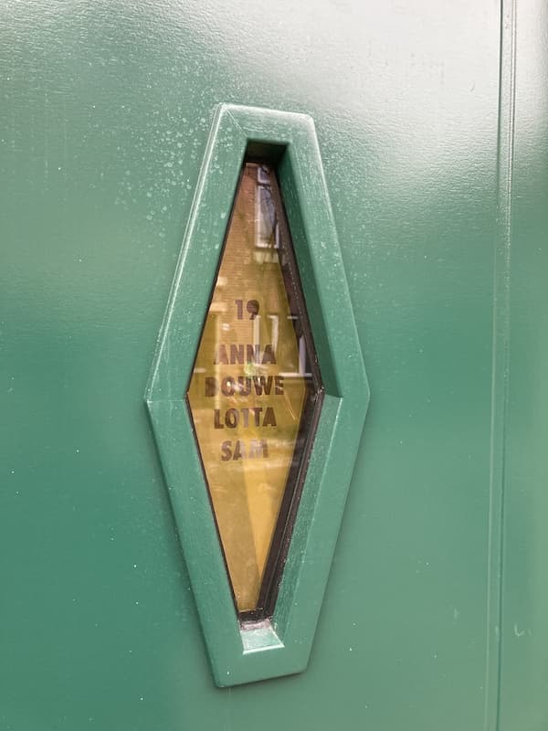
Assignment #4 (D) - Making a vinyl cut design.
We have a new door in our house. Our name tag has disappeared and the new door has a funky little window in the middle. The plan is to make a nice vinyl sticker for this window with our names and house number on it.
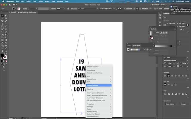
I made the design in Illustrator as this is super-easy. There are no parameters used in this design.

In a attempt to import this design in mods, I encountered my first error.
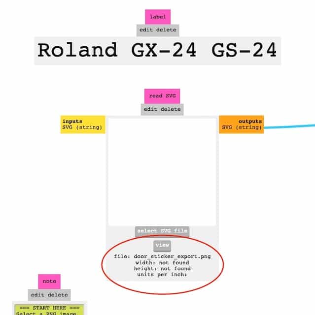
It turns out that you should not try to import an png file in the svg module... ahem
As mods added the file, and I inspect the path how it cuts, it appears as if the single line in Illustrator is made into two lines in mods.

This will not matter for the end result as it is the other line, but it is rather confusing and I would like to know why this happens so I an prevent it from happening if it does matter in another design.
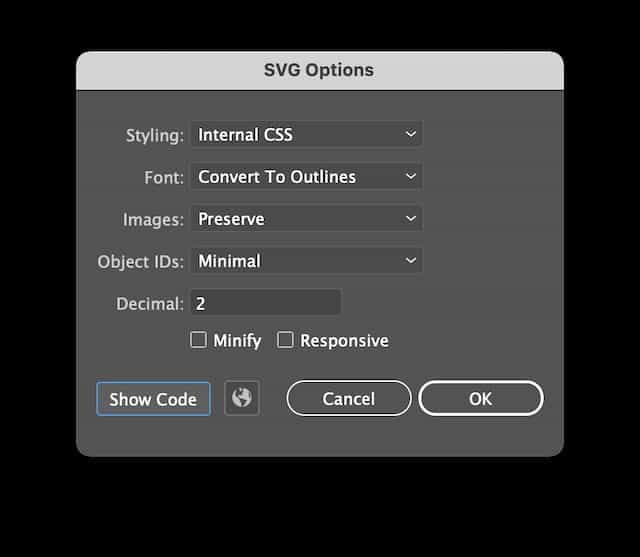
By now I found out this does matter. And I switched to SVG instead of PNG. It is important that you choose the right export setting in Illustrator, otherwise mods does not recognize the file. Here are the settings I found to work so far:
Problem: cut a line.
In illustrator I placed a line around my design. This line is ill-recognized by mods. It either makes it into two paths or into one weird path. When I make the line thickness 0.6 points it shows both issues in one file
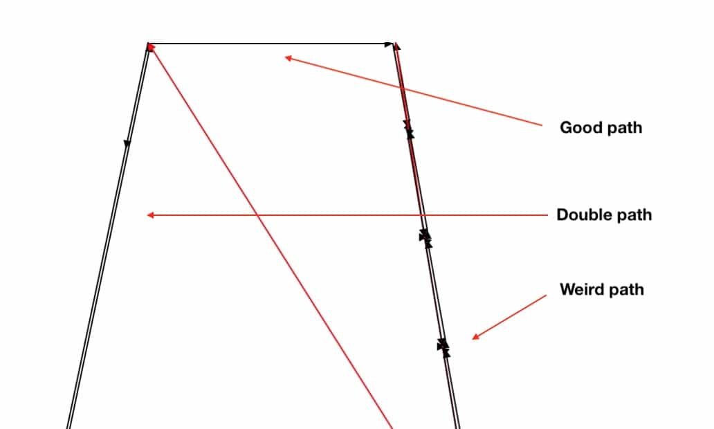
When I don't make a line, but only use fill color, it seems to go better. Mods has issues to represent correctly what I made, but Henk believes he did understand it. I guess the proof of the pudding is in the eating. And I just have to cut this damn thing.
I solved this by not using any lines in Illustrator. I repeat: DO NOT USE LINES IN ILLUSTRATOR! You can simply fill the parts you want to be gone, and leave the parts you want to keep white...
This file worked well:

NOTE you need to place a few extra pixels around your model as Mods does not work well when the design in your .SVG comes all the way to the edge. The extra pixels around it make sure that all the parts that you really want to have cut are really cutted.
See this png as an example.
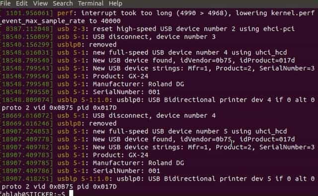
Operating the Roland CX-24.
We operate the CX-24 with mods. Mods can be installed on your own computer, but we have it ready for us on the Ubuntu machine hooked up to the CX-24.
There are steps to remember on the computer (mods) side and on the hardware side.
First the hardware side.
- You pull up the leaver on the back to make space for vinyl to go in. You can either use a little piece, or take a roll from under the desk.
- You adjust the vinyl in the cutter and you can use the little lines on the front to align it so it sits straight.
- There are two little wheels that guide and press the material through the cutter. These can only be positioned in the white ares. Otherwise you get an error.
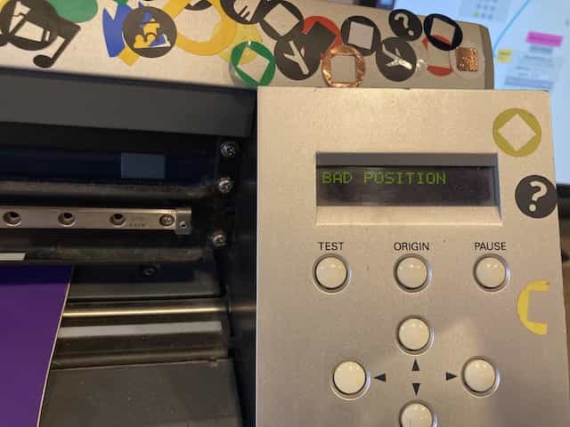
NOTE Position the wheel before you do anything else as they determine the width of the piece you can cut. If you have a wide piece to cut and you forget this, you have to power off the machine, adjust the wheels and power it on again.
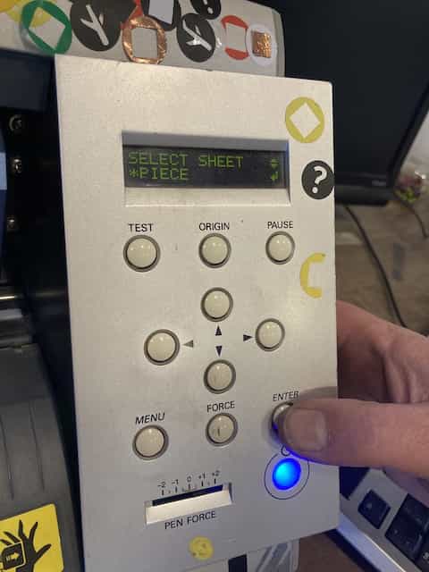
- You also have to tell the CX-24 what you chose to use (piece or roll)
You can then use the arrows on the machine to position the knife in the desired position.
Now bend your knuckles, roll up your sleeves and open mods...
Now the software side.
Mods is a community project that forked the tool from Neil. Neil started mods out of frustration with printer drivers that are installed by default on any type of printing machine. These drivers are the main and maybe only reason why printers still behave like it is the frikkin' 80's.
Mods gets the printer driver out of the way and gives you direct access and control of the machine from a browser. Mods is basically some JS and HTML5, but has a websocket that can talk directly to a range of ports on the CX-24 that are opened by the mods software.
You hardly will ever need to use the terminal as the web interface has all you need. The design reminded me of hotglue. (and I have to suppress the urge to do my documentation in Hotglue from now on...)
NOTE You need to start the mods server by hand when you login to the ubuntu machine. You do this by opening a shell and typing: $ cd ./mods && bash mods.
If you use mods and notice that the printer doesn't react to your command, you probably forgot this step.
The Interface of mods
These are the most important modules.
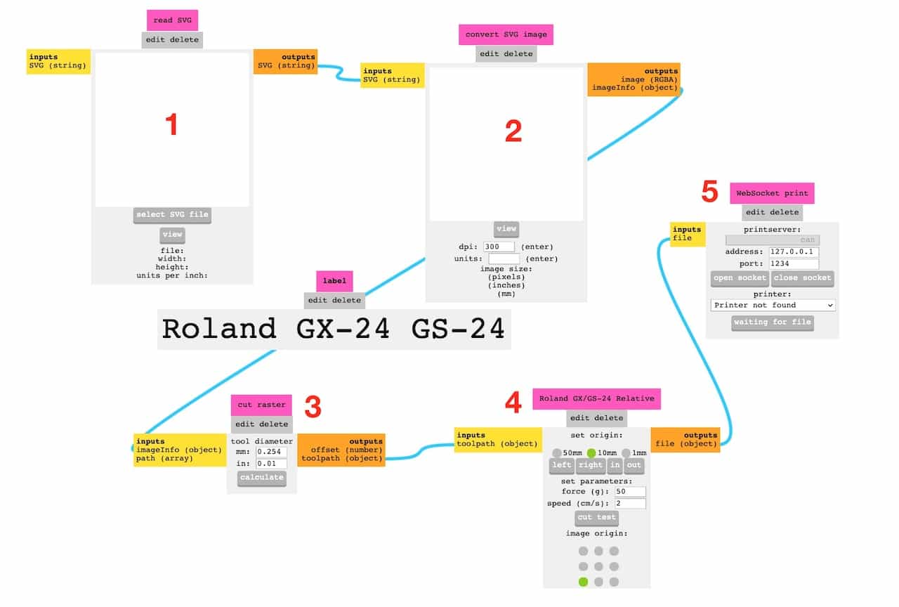
- Import a SVG file and calculate it
- Check image size
- change GX-24 knife force and diameter. Only the force matters and often a setting between .5 and .7 is good
- Set the origin and make a cut test.
- send the file to the printer
The End Result
The end result is nice. I am happy with it for now. But probably I am going to make another, even better fitting version later on. Also the color is not as I hoped it would be; more translucent then I hope for and therefor the letters are hard to read in daylight.
What I learned
- Don not set the guiding wheels in a wrong position.
- Removing vinyl and reinserting it is kinda like a reset of the machine
- If you want to cut something, check the cutting in mods, otherwise you waste material.
- If you want to make a sticker for window; make sure you mirror your design.
- I needed 16 files before I got it right. And I am still not 100% satisfied with the end-result. The material is too translucent.
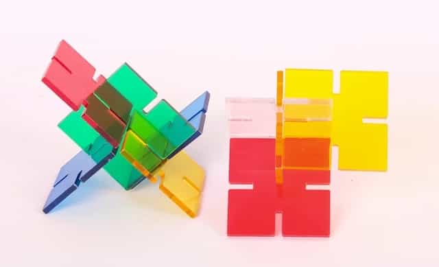
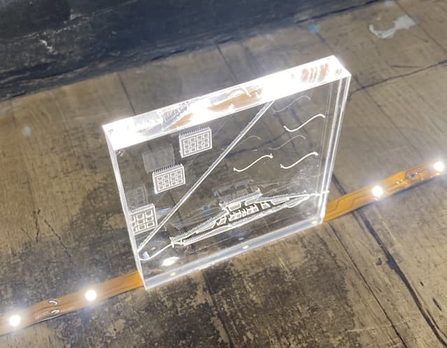
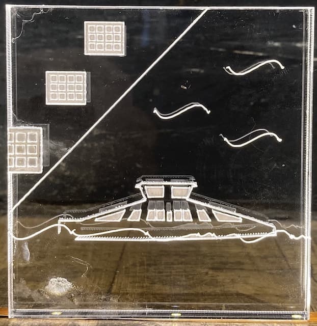
Assignment #3 - A little acrylic ferry.
The last thing I did was making a test with Acrylic and seeing how I could play with the depth of cutting.
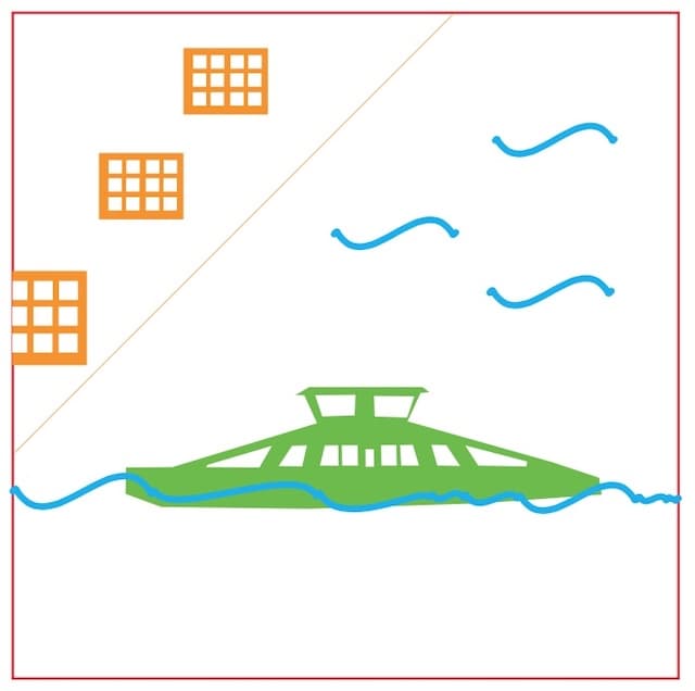
For this test I:
- used a rather thick piece of acrylic
- Made a drawing with different colors
- set the laser to cut the different colors at different speeds and depths
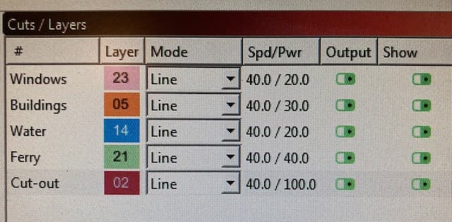
I placed the resulting thing on a strip of LEDs so it was shining through the bottom. My hope was that the different depths of the cuts would break the light in different ways. And although the result was nicer then I had hoped for, the effect of different cuts was not very clear.
Stuff I learned:
- I need to play with more settings.
- I need to think now if this is really what I want to use
- Acrylic stinks. I also don't like to use this material as it feels so polluting...