Electronics Production
Quote of the week:
Yesterdays group made no mistakes. That was very unfortunate.
~ Henk ~
Description
We started milling and soldering. we make our own board on the milling machine and then we solder the components to it.
Assignments - Learning Outcomes
| # | Assignment | Fin |
|---|---|---|
| 1 | Characterize the design rules for your PCB production process: document feeds, speeds, plunge rate, depth of cut (traces and outline) and tooling. | 1 |
| 2 | document your work | 1 |
| 3 | Make an in-circuit programmer by milling and stuffing the PCB, test it. | 1 |
Have you?
| Spirals | Description | Done |
|---|---|---|
| A | try other PCB fabrication process. | 0 |
| B | Documented how you made (mill, stuff, solder) the board | 1 |
| C | Documented that your board is functional | 1 |
| D | Explained any problems and how you fixed them | 1 |
| E | Included a ‘hero shot’ of your board | 1 |
| F | make a beautiful board | 0 |
Assignment #1 & #2 - Characterize the design rules for your PCB production process
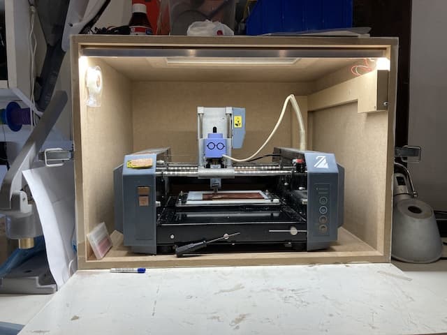
We have a Roland MDX Milling Machine. Henk loves it. It is strong, precise and reliable. We use Mods to control it.
You can adjust setting to steps of 0,006mm. We use two types of milling bits. To make the traces we use a 0.4 mm drill. To do the cutout we use a 0.8 mm drill.
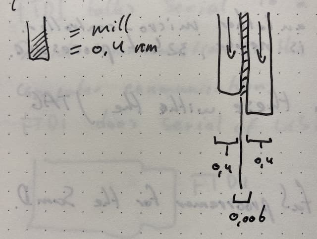
Bits There are different kinds of drills. 0.4 mm is for tracing. 0.8 is for cutting out the board. 0.1 is a thinner bit for tracing but we don’t use them as you break them faster then you can order them. Drills can have 1 flute or 2 flutes, or one knife or two knifes. Henk is unable, or unwilling, to explain why these exist. He claims there is no difference between them.
We save the 0.8 cutting drill on the front of the machine and the 0.4 in a little box. In the box are normally two drills. The right drill has two flutes. The left drill has one flute.
To start we made the PCB test board you see here.
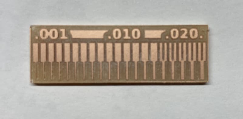
But just how we did that, I will tell you now.
The material we are milling is FR1 (or Phenolic paper). This is copper on pressed paper. Standard circuit board material is FR4, which is made of glass fibers. Milling that is much more hazardous for people and for your tools.
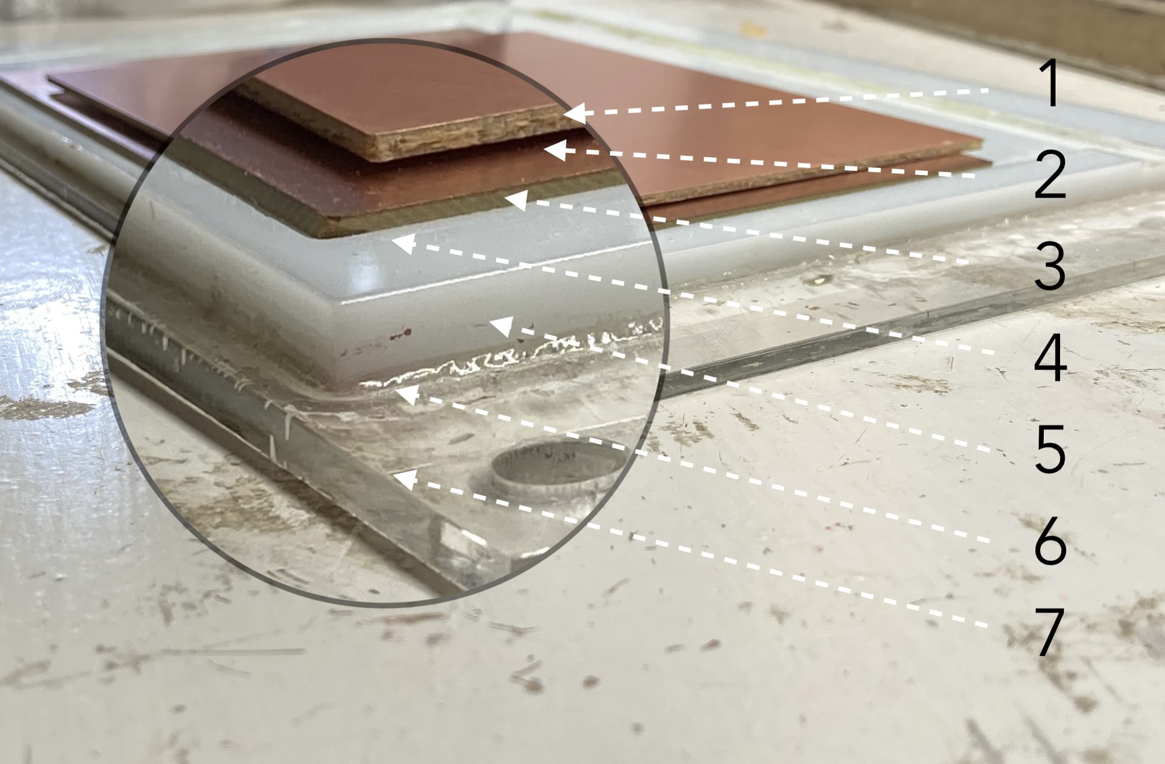
The material sits on the cutting bed. The cutting bed exists of no less then seven(!) layers. From top to bottom it is:
- FR1, the material your are actually cutting.
- Double sided tape to make the material stick to the
- Copper plate, or sacrificial layer that you can cut into, but should better not.
- Double sided tape to make the copper stick to the
- White Acrylic bed that the machine itself drilled to make sure it is 100% flat.
- Acetone which more or less melt together with another layer of
- Transparent acrylic layer which has holes in the corners with which you can attach it to the machine.
I had to replace the FR1 layer once. It was done by
- removing the old layer
- clean it sacrificial layer with alcohol so no sticky parts or dust remain
- put new parts of double sided tape on it
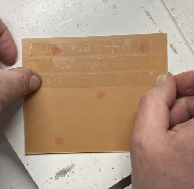
- press it hard on a soft surface so you don't damage the new board.
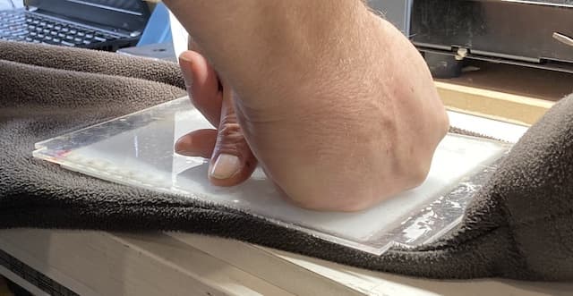
- mount the whole shebang back in the machine
- use the screws to keep everything in place and not more then that: no need to tighten the screws very hard as you will mal-adjust the layers!
The milling action.
We use the materials from this place
The first board we are making is the hello.USB-UPDI.FT230X. You can find the files to make this board here:
Software Mods
Just like with vinylcutting, we use mods to cut. in this case we use the Roland DMX PCB module.
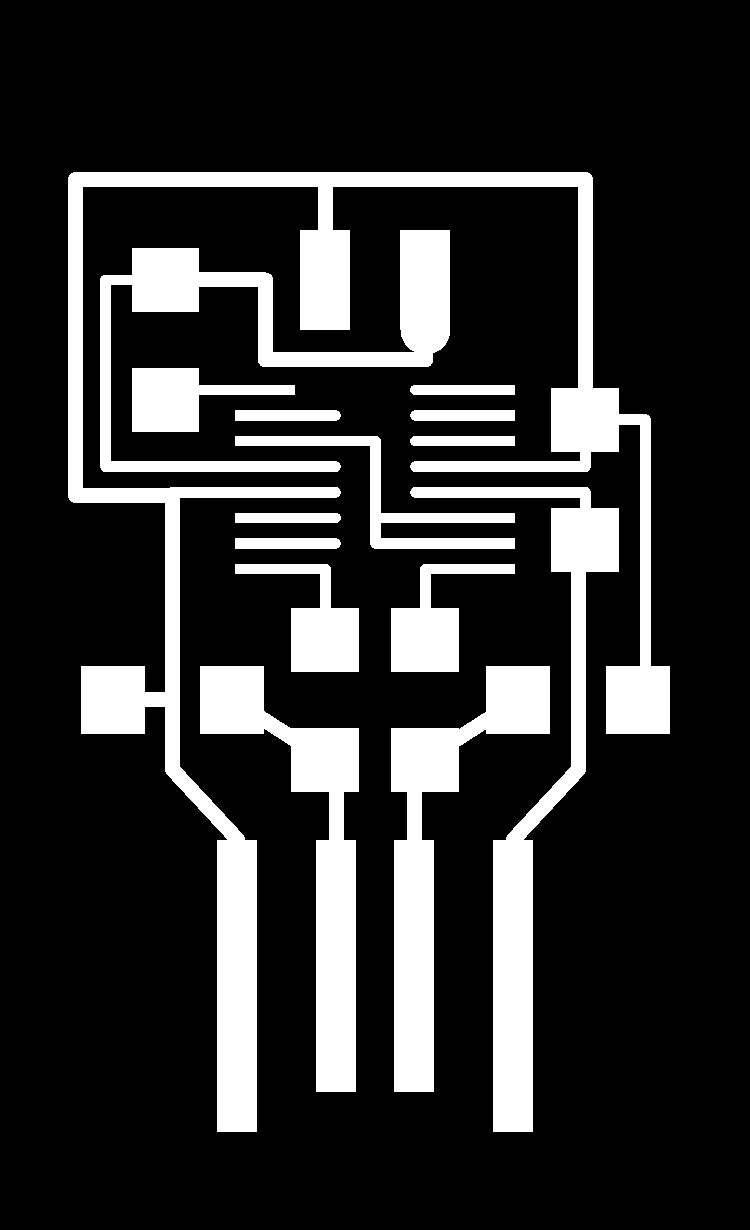
Tracing
We are first going to trace the inner parts of the new PCB. You load the module and then use the fault setting for Mill traces (1/64). This has, almost, the perfect settings for a nice PCB creation.
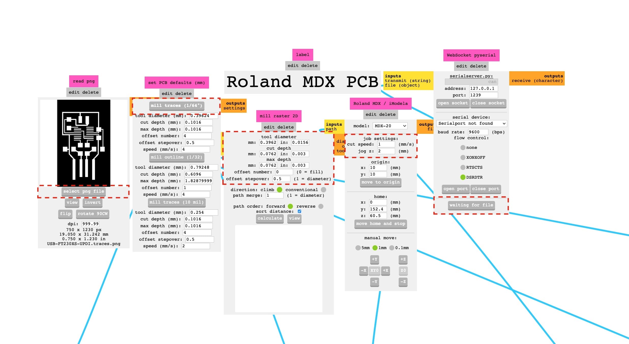
Mill Raster
| Field | Setting |
|---|---|
| Tool Diameter | 0.0156"(default) |
| cut depth | 0.003" |
| max cut depth | 0.003" |
| Offset number | 0 (This removes all excess copper) |
| offset stepover | 0.5 (default) |
| path order | forward (default) |
| sort distance | checked (default) |
Roland MDX / iModela
| Field | Setting |
|---|---|
| cut speed | 1mm/s |
| jog z | 2 mm |
NOTE: the other settings in this field are dependent on your current job. The origin will always change for example.
The actual milling.
here you see the, much slowed down milling going on. And the lowering to a new level in the corner
After we set all the software part correctly, we
- turn on the machine (green button)
- check the drill that is in the machine (visual check)
NOTE This should be the 0.4 drill, not the 0.8. That one we use to cutout the board in the second cutting
- put the machine into view mode (view button)
- set the origin for cutting. (using the x an y settings in mods)
- send file to machine.
NOTE Write down the origin. You need it again to do a proper outline. Just in case someone closes the tab when you are at the toilet.
Opening and closing of the sockets and the ports.
In the terminal type $ mods.
This opens the serial connection to the miller and a browser tab with the mods software opened in it.
You have to make sure you pick the right machine before you start. (Roland MDX)
In modes you have to do this little dance to make sure that the right ports and sockets are closed and opened. You can check if it is working by changing the origin. If the mill doesn't move, you missed a part.
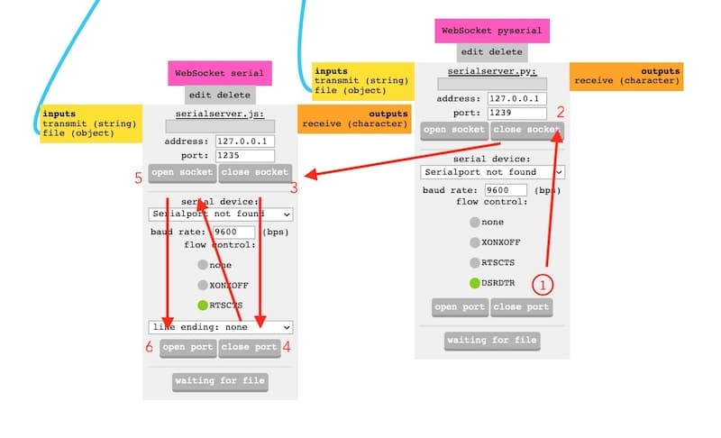
Then you check all the settings again. And again. And if you are really sure (can you ever be...?) then you send the file to the machine. And it starts.
Here is my first cut. It is definitely not the deepest.
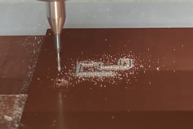
And as it turned out, it was not deep enough. This seems to be a major pitfall: again, like in the group assignment, the cut was not deep enough.
Pause and cancel routine.
If you want to check your milling process, you can safely press the View* button, vacuum any excess dust away and have a good look at the board. When you are done checking, just press View* again and the process will continue where it left off.
If you find that something has gone wrong, you can abort the milling by doing the following steps:
- press cancel in mods
- hold the up and down button on the MDX for 10 seconds.
You can then adjust settings in Mods and send the file anew to the machine. Depending on the state of your milling so far, you can continue in the same place, or start a new mill.
In my case, the milling was not deep enough, so I continued in the same place and made the existing mill traces simply deeper.
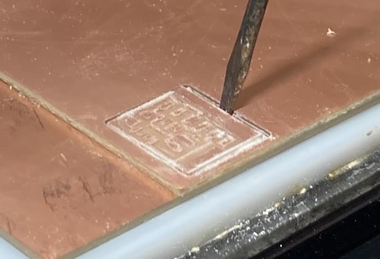
Outline
We then cut out the PCB from the surrounding material with a 0.8 bit. Move the mill to a convenient position where you can change the bit and don't forget to set the Z-alignment again after the bit has changed.
Cut out.
Two different files are needed for tracing and cut-out. First you do tracing. Then the cut out.
- Change the drill to 0.8mm
- For cut out you load a new file
- Select Milling outline from the defaults
- Choose offset 1 in the Mill raster Module
- Calculate and view your model
- Speed may now be changed to 4
- In the Roland module place the origin at the exact same spot as you used for the tracing file.
- Give Z-axis drill head more space than during tracing. 1.55 in our case.
- Lower the drill unto the board.
- Close and re-open ports and web sockets are open in case nothing happens...
- Send file.
NOTE The max depth of the milling need to be set to marginally more then the material thickness. In our case this is 1.55mm
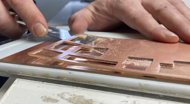
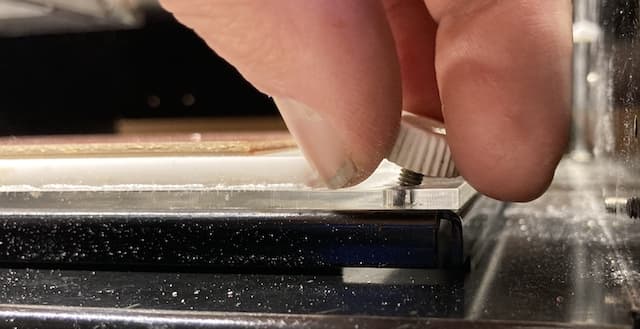
The drill will make several round around the area. Each time it cuts a little deeper. When done, use the vacuum cleaner to remove all dust from the board. You can use the little black screwdriver to flip your component out.
Take a little double sided tape to paste the board to the table and use normal 80grams paper to sand the board. You can also use a fingernail to gently remove 'braampjes' and push the copper in place.
Then clean the board with soap and water and dry it though roughly with towel-paper.
Assignment #2 & #3 - Soldering
I pasted my little board to a piece of paper so it stays in one place, and I can easily turn it. Golden rule with soldering:
- small parts first
- work from centre to edge
This way your parts are not in the way of soldering.
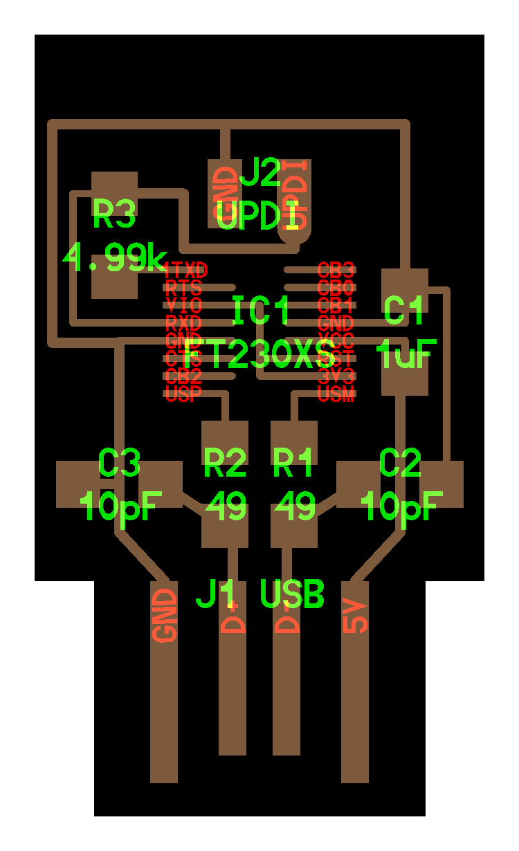
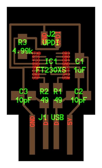
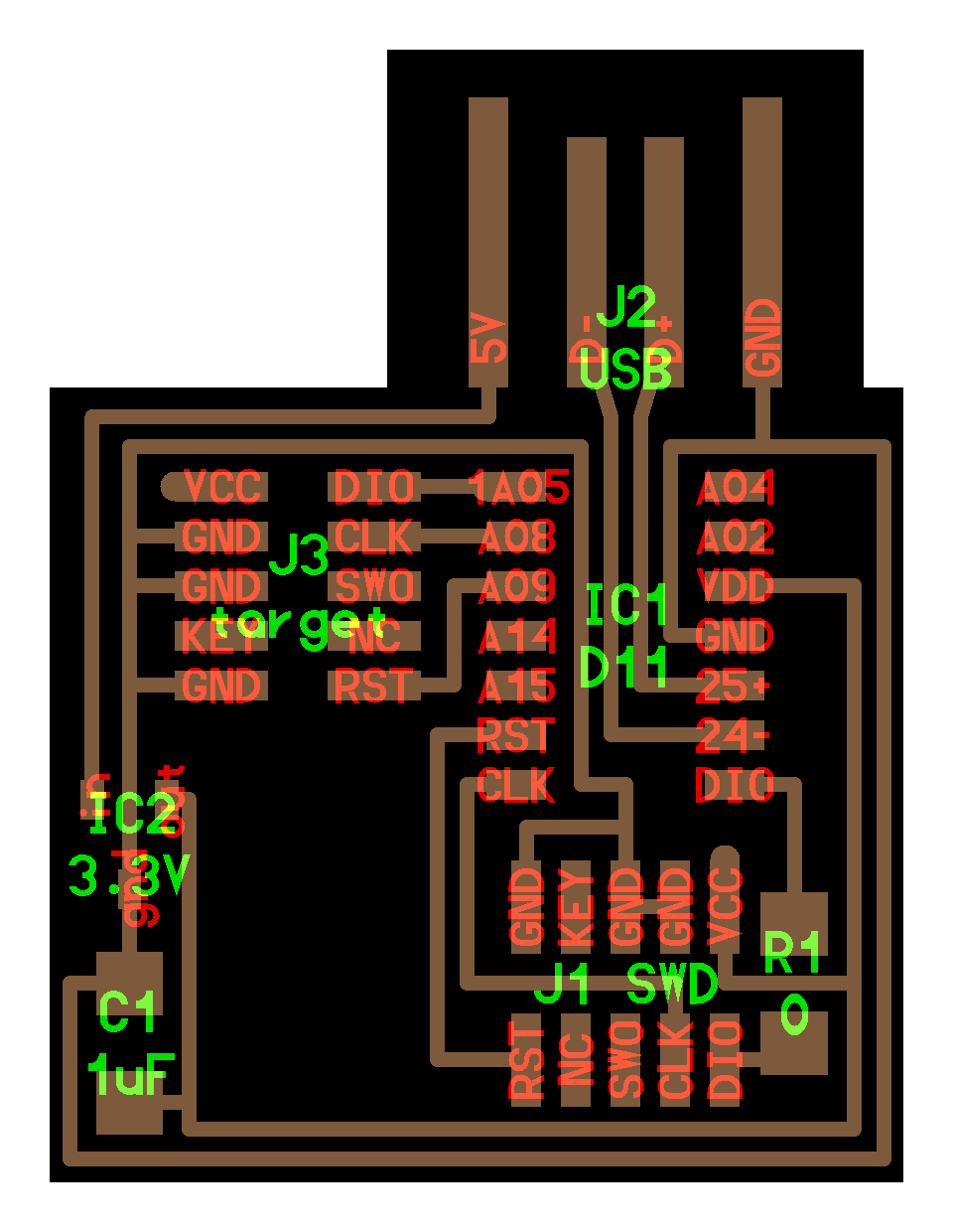
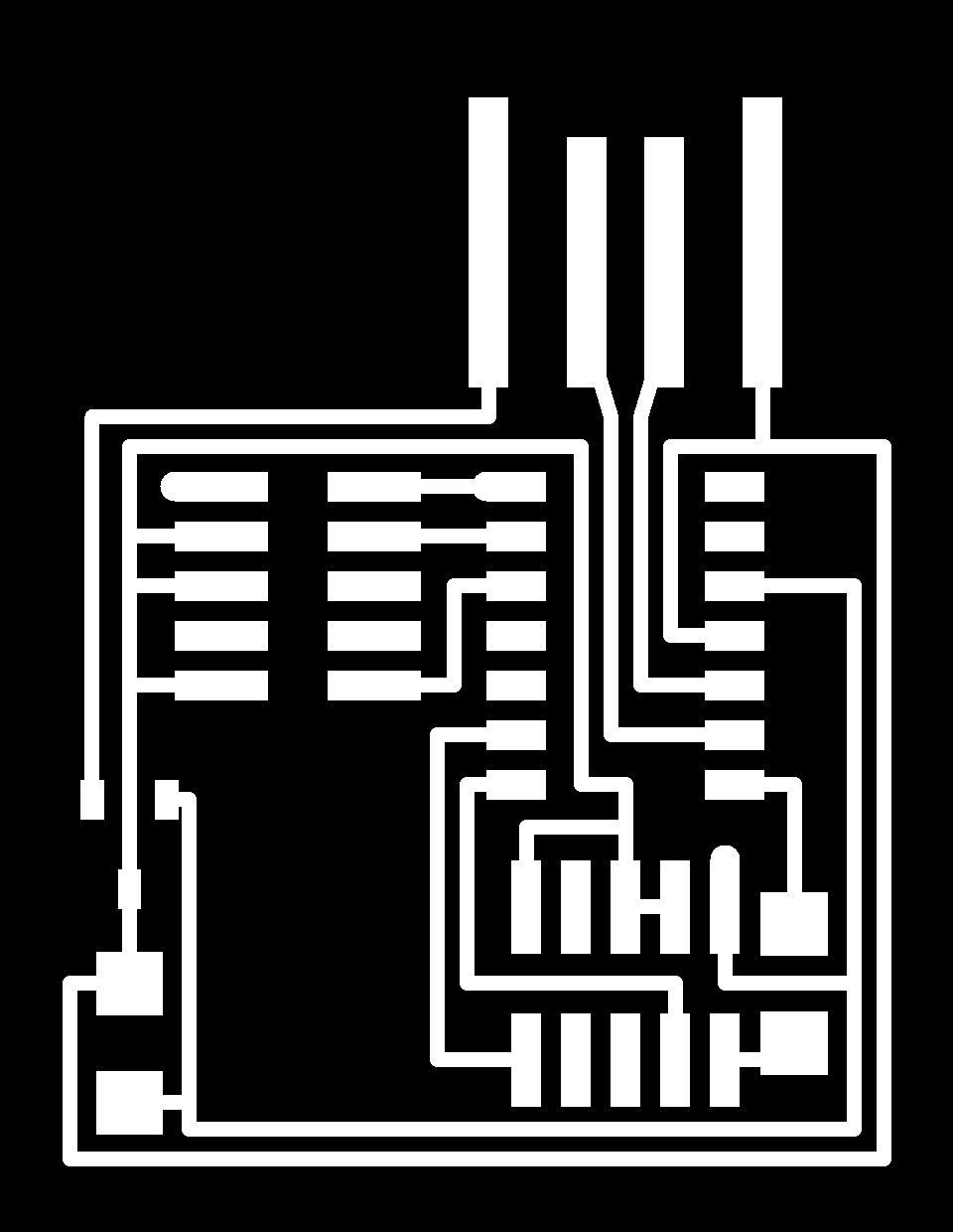
To know which parts to solder you have two pieces of information. One schematic with all the part names and one picture of the finished part. You need both.
When you take parts from the shelf, just take one piece. Take the box to your desk. When you are don, put that box back in the shelf and repeat with the next part.
When you put a part on the board, don't forget to check polarity. Cross-checking your parts orientation at least twice against the visual example of the finished board is not luxury.
Soldering in action preparing the solder pin: 1. Let it heat up. 2. Clean tip on wet sponge. 3. Add solder. 4. Clean tip again. Now you have a nice clean tip with a film of solder on it.
The Soldering Dance 1. Heat both trace and component leg. 2. Apply solder. 3. Retrieve solder wire. 4. Keep pen down. For a couple of seconds to keep the solder flowing. Retrieve pen.
To solder a small component. 1. Heat an island. 2. Apply a little blob of solder. 3. Get component between your tweezers. 4. Put 1 leg on top of blob. 5. Heat solder with pen. 6. Push leg in place. 7. Manoeuver the component in the right place. Are all legs nicely fitted on a trace?
Note: even if components have no orientation, you can place the lettering in the same direction for easy reading.
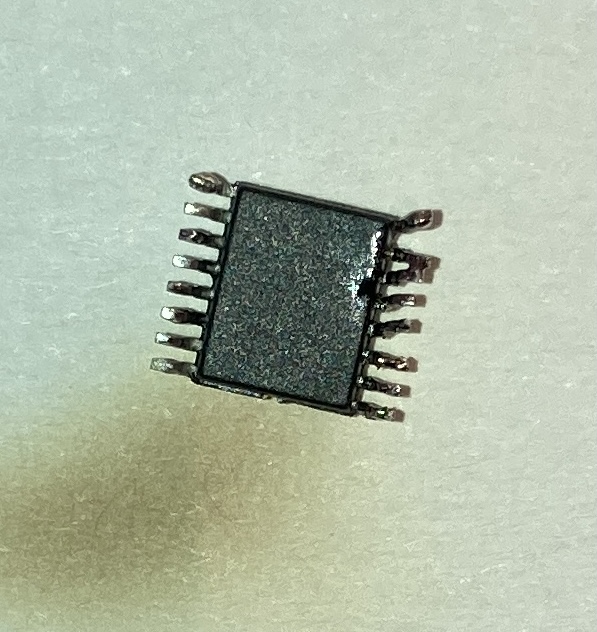
Then you start to dance. I first put the FT230XS in place. To keep the item in place I first solder one of the legs with a tiny blob while I keep the part in place with my tweezers. As soon as it is stuck I solder the other parts which goes really well. I am almost done and doing the last two legs as a big blob of solder gets stuck between the legs. I tried to wipe it out but smear it back to the third leg. Further attempts to repair with the heat-blower and the heated-sucker gun only made things worse. To the point where all was lost...
Henk made an attempt to repair, but no luck... So I used the heatblower to pull the FT230XS off again and start with a new one. The old one had all bent legs by now.
The new one went smooth; all was quickly in place thanks to the solder that was already on the board. I could flow that and press the legs in.
The other, slightly bigger components, were even easier. So my board was suddenly stuffed and ready to test rather fast. Sadly it didn't work.
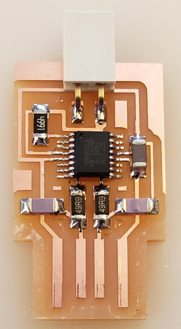
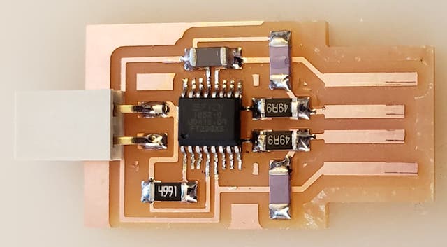
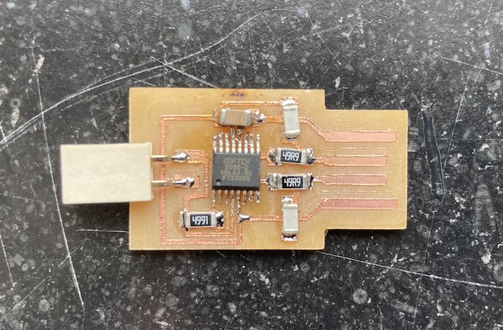
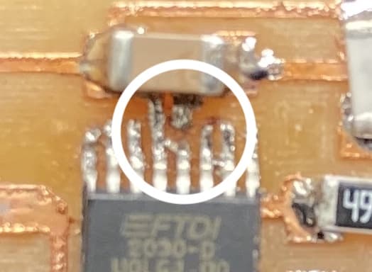
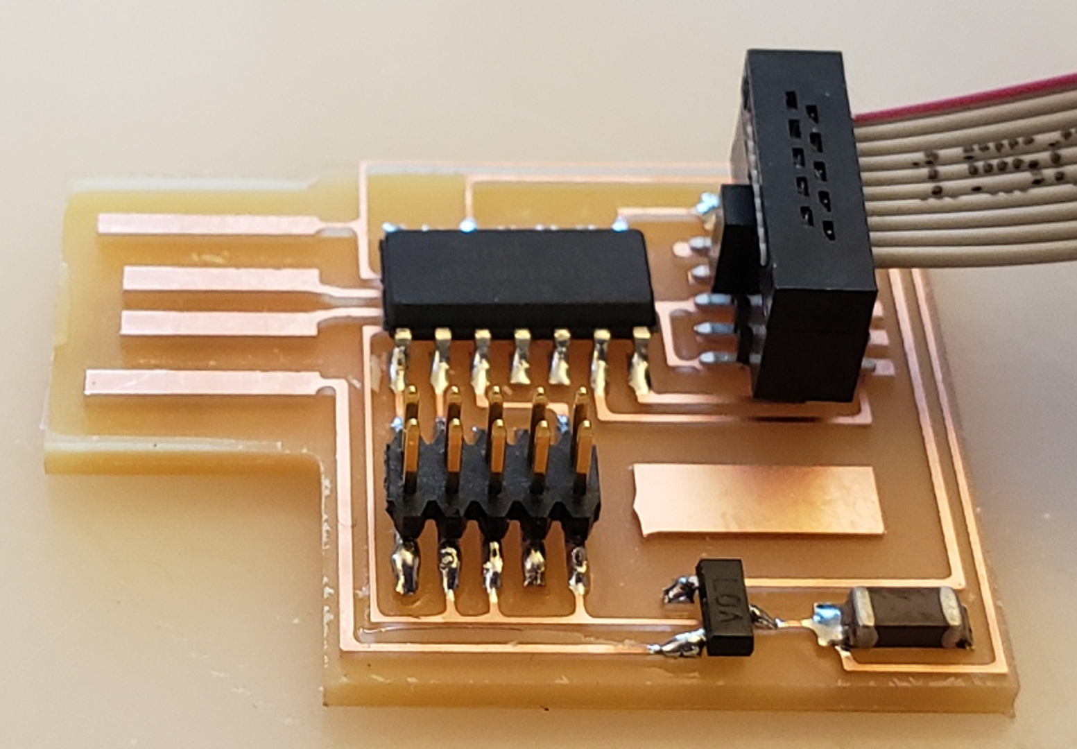
This is how the board currently looks.
This part is broken
Henk does not allow me to make a new board, so we have to fix this one. Sadly I ran out of time on Monday. So we have to try again tomorrow.
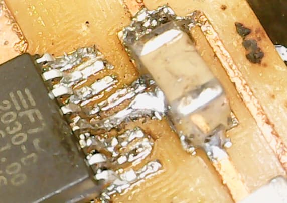
The next morning, by the time I came in, Henk fixed it with a flying solder bridge.
The problem
The traces for the solder was gone. I think it was too thin due to the second milling round as he first one was not deep enough (see above) and that the fooling around of me damaged the already rather thin trace.
And as solder only sticks to copper and not to FR1 it was impossible to get the connection back. So Henk made a bridge through the air with solder to connect both sides.
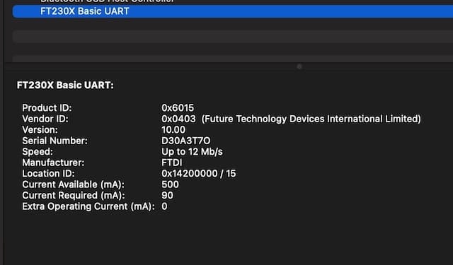
The board now works and show up in my system report.
Hello SAMD
The SAMD is a JTAG programmer. hello.CMSIS-DAP.10.D11C
You can find the files to make this board here:
On the optimistic beat of the morning I start to mill a second board. The SAM-D. And I tumble into an avalanche of mistakes:
- A tale of two mods: I have some issues with communicating to the miller and find out that I have two tabs in Firefox open with mods. Shouldn't do that...
- The z-incident: when you lower the drill to its max, and then tighten it... it can't go any lower then it already is and will, upon drilling, only scratch the surface of your board.
- An Edge Case: I was using the last space on the mounted board left. All the way in the top-corner. So when the drilling started, it turned out that the origin was alright, but that the top-right of the board I was making was on the edge.. Or even a little over the edge. I guess that, as with the laser-cutter, a frame test would come handy in such cases.
- Screw on the loose: When outlining the board the drill was not going deep enough. Again. And as the mill went up, at the end of the drilling routine, the drill stayed down... it seemed that I had not tightened the drill enough in the hole. So it could not be pushed down enough and almost fell out when the mill went up.
One thing I did change is the max_cut_depth. I was tired that it had already played parts on me so many times. So instead of 0.003mm I used 0.004mm as max cut depth in the SAMD.
Soldering the SAMD
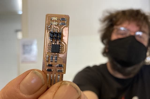
This was a true joyfull walk in the park. I got the rhythm, I got the style and the result was something I was proud of:
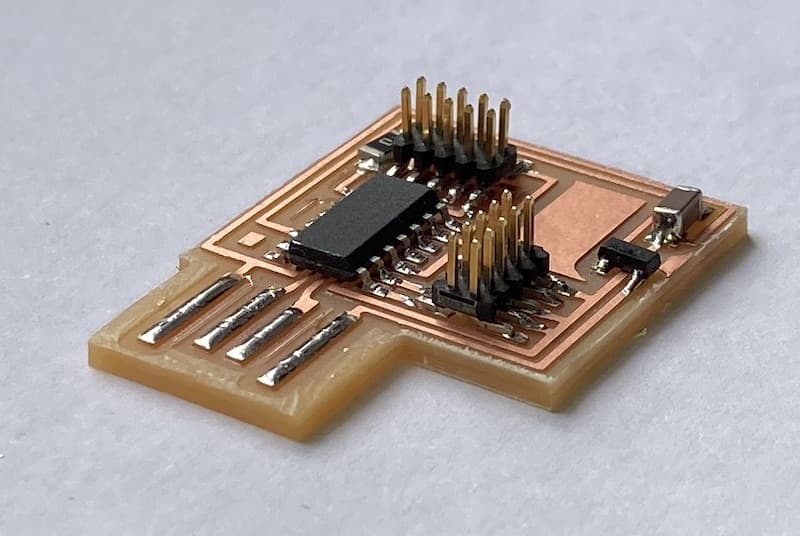
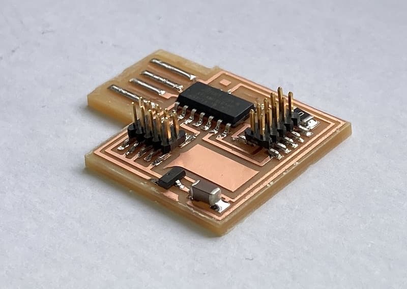
The solder is shiny, in the right spots and the board worked immediately. The big difference is of course the IC part: this one has much larger legs.
Research
Tessels Fabacademy documentation from last year helped me a lot.
Apart from that my fellow students Phil, Lucia and Nadieh helped me out a lot on these days.