Week 13: Embedded networking and communications
Assignments:
-
Group assignment: send a message between two projects
-
Individual assignment: design, build, and connect wired or wireless node(s) with network or bus addresses.
What to learn:
-
Demonstrate workflows used in network design
-
Implement and interpret networking protocols and/or communication protocols
Have you?
-
Linked to the group assignment page.
-
Documented your project.
-
Documented what you have learned from implementing networking and/or communication protocols.
-
Explained the programming process/es you used.
-
Outlined problems and how you fixed them.
-
Included design files (or linked to where they are located if you are using a board you have designed and fabricated earlier) and original code.
DOUBT: What does “two projects” mean in the group assignment? Answer: You need to send a message between any combination of boards, computers and/or mobile devices. You need to write code that sends or receives the message in question.
DOUBT: Do I have to make new boards for this assignment? Answer: No. You can use any board you have designed and fabricated from an earlier assignment.
DOUBT:Can we use arduino/commercial boards for networking? Answer: Yes, provided one of the boards is of your own design and fabrication. Commercial wireless modules can be used provided they are integrated into your own design. You can use a commercial networking module as long as it is integrated in your own design. Note the difference between board and module - those are two different things.
DOUBT:Must each board have a unique identity? Answer: It does not have to be hard-coded but you must use some form of addressing.
What is networking and communications?
I found a very useful site on serial communication. Sources and figures below are from this website.
Embedded electronics is about interlinking circuits to create a system. These systems need to change information and for this a communication protocol is used.
The data they send between them appears in bits of data. A bit is like a letter except it is binary so it can only be either a 1 or a 0. Bits are transferred from one device to another by quick changes in voltage. In a system operating at 5 V, a 0 bit is communicated as a short pulse of 0 V, and a 1 bit is communicated by a short pulse of 5 V.
These bits of data can be transmitted through two types of communication protocols: parallel or serial.
-
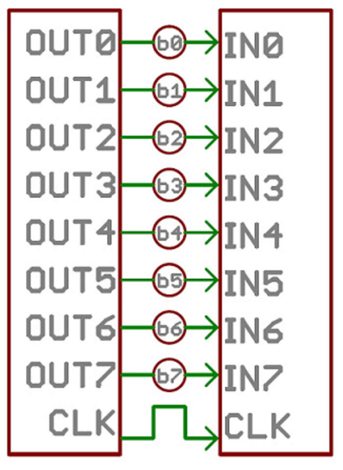
“Parallel interfaces transfer multiple bits at the same time. They usually require buses of data - transmitting across eight, sixteen, or more wires. Data is transferred in huge, crashing waves of 1’s and 0’s.” The following image shows an 8-bit data bus, controlled by a clock, transmitting a byte every clock pulse. 9 wires are used:
-
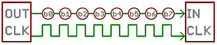
“Serial interfaces transfer their data, one single bit at a time. These interfaces can operate on as little as one wire, usually never more than four. The following image shows serial communication transmitting one bit every clock pulse with just 2 wires.
The following example helped me understand why we use serial communication in the Fab Academy: “Think of the two interfaces as a stream of cars: a parallel interface would be the 8+ lane mega-highway, while a serial interface is more like a two-lane rural country road. Over a set amount of time, the mega-highway potentially gets more people to their destinations, but that rural two-lane serves its purpose and costs a fraction of the funds to build. Parallel communication certainly has its benefits. It’s fast, straightforward, and relatively easy to implement. But it requires many more input/output (I/O) lines. If you’ve ever had to move a project from a basic Arduino Uno to a Mega, you know that the I/O lines on a microprocessor can be precious and few. So, we often opt for serial communication, sacrificing potential speed for pin real estate.
Also, Neil explained the purposes of wanting to make communication networks:
-
Location: to connect from far distances.
-
Parallelism: to divide the work up, to make a system out of many processors instead of one big one.
-
Modularity: instead of having one system that does everything, it can be broken up into smaller modules, develop modules separately and combine them to make one system.
-
Interference: to split the system so that parts from it do not interfere.
Types of serial communication: both sides need to speak the same language. In electronics, these languages are called communication protocols.
There are only a few communication protocols when building DIY electronic projects (like the ones we do at the Fab Academy): asynchronous serial, SPI and I2C. These are slower than protocols like USB, ethernet, Bluetooth, and WiFi, but they’re a lot more simple and use less hardware and system resources. They are ideal for communication between microcontrollers and between microcontrollers and sensors where large amounts of high speed data don’t need to be transferred.
Asynchronous serial communication:
This type of serial communication means it transfers data without the help of an external clock signal. This means it will use less wires and I/O pins. You also have to put extra effort to make sure you are reliably transferring and receiving data.
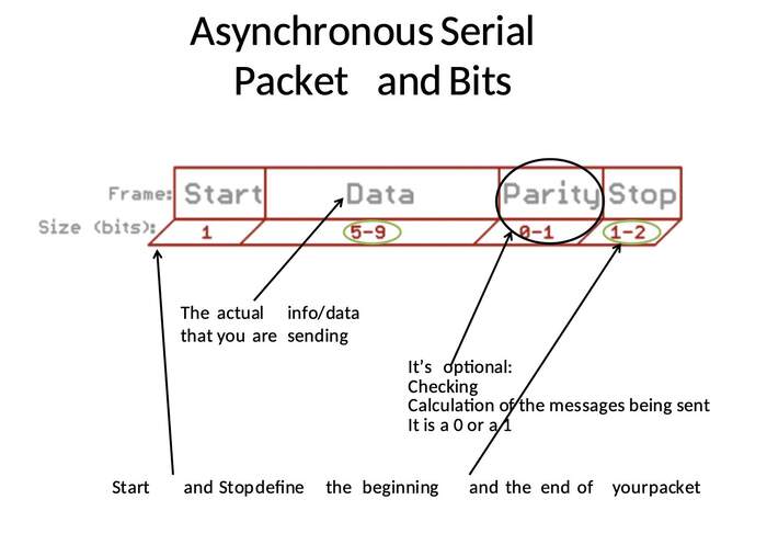
Rules of Serial how to make serial packets: The asynchronous serial protocol has a number of rules to help ensure error-free data transfers:
-
Data bits: the data it is carrying, this is from 5 to 9 bits. The standard data size is your basic 8-bit byte, but other sizes have their uses. A 7-bit data chunk can be more efficient than 8, especially if you’re just transferring 7-bit ASCII characters. Both serial devices also have to agree on the endianness of their data. Is data sent most-significant bit (msb) to least, or vice-versa? If it’s not otherwise stated, you can usually assume that data is transferred least-significant bit (lsb) first.
-
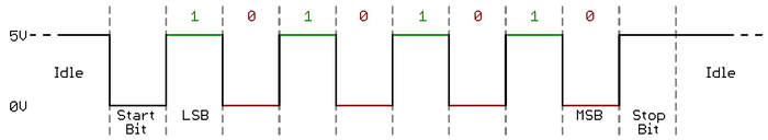
Synchronization bits: these are the start bit and the stop bit(s). There’s always only one start bit, but the number of stop bits is configurable to either one or two. The start bit is always indicated by an idle (not moving) data line going from 1 to 0, while the stop bit(s) will transition back to the idle state by holding the line at 1.
-
Parity bits: parity is a very simple way of checking errors. It is optional, and not very widely used. It can be helpful for transmitting across noisy mediums, but it’ll also slow down your data transfer a bit and requires both sender and receiver to implement error-handling to check the following. It comes in two types: odd or even. Basically you add up the data bits, for example; 001011101. Then you check if the sum is even or odd, in this case odd; 5. If the parity mode is set to even, and the sum of the bits is odd (5) the parity bit would be set to 1 (this would make the end-total number even, responding to setting the parity mode to even). If the parity mode is set to odd and the parity bit numbers sum up even numbers then the parity bit would be 0.
Image showing frame of bits/ packets (where data is when transmitted), they are created by adding synchronization and parity bits to our data:
- Baud rate: the speed of data sent over a serial line (expressed in units of bits-per-second (bps)). This value determines how long the transmitter holds a serial line high/low or at what period the receiving device samples its line. The most common baud rate is 9600, and the highest 115200 but the faster the speed also the more error you are likely to get.
There are multiple ways to configure the protocol through these signaling rules but the most important part is to ensure both devices on a serial bus are configured to use the exact same protocols.
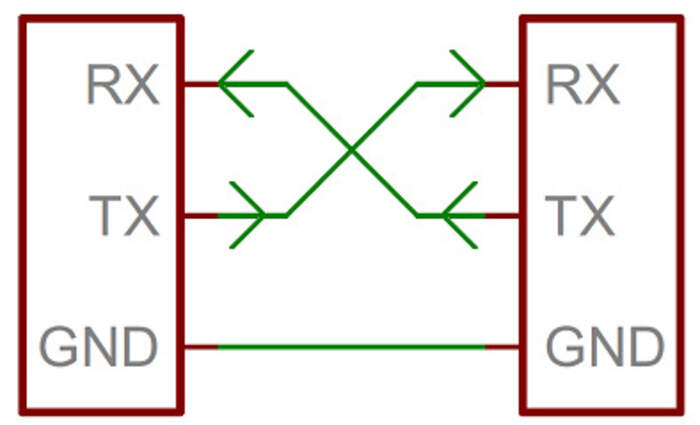
The hardware part is how to connect the devices to see how the 1’s and the 0’s and the baud rate are implemented at signal level. A serial bus consists of 2 wires, one for sending data and one for receiving data. Serial devices should have 2 serial pins: the receiver, RX, and the transmitter, TX. (We have worked with this with the FTDI). The RX from one device should go to the TX of the other and vcvs. The transmitter should be talking to the receiver, not to another transmitter.
-
A serial interface where both devices may send and receive data is either full-duplex(both devices can send and receive simultaneously) or half-duplex(serial devices must take turns sending and receiving).
-
Some serial buses work with one single connection between a sending and receiving device. For example, our Serial Enabled LCDs are all ears and don’t really have any data to relay back to the controlling device. This is what’s known as simplex serial communication. All you need is a single wire from the master device’s TX to the listener’s RX line. I have realised this happens for example for the PIR sensor (it only has one wire).
The following are 2 of the most common standards for serial signaling:
- TTL: When microcontrollers communicate serially between them they do so at a TTL level which stands for transistor-transistor logic. It is much easier to use within embedded circuits but the low voltage levels means it can loose some data on the way if they are long transmission lines.
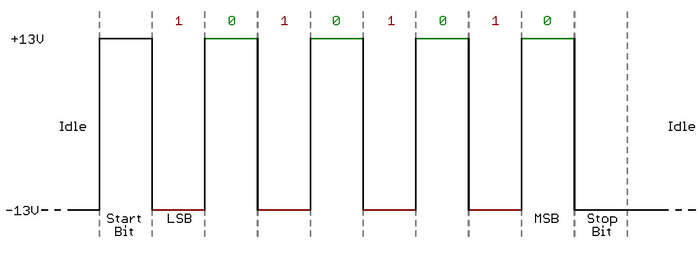
- RS-232, which can be found on some of the more ancient computers and peripherals, is like TTL serial flipped on its head. RS-232, or more complex standards like RS-485, are better suited to long range serial transmissions.
Remember to match the two serial devices’ voltages, you can’t communicate a TTL serial device with an RS-232 bus.
As we have used in previous week we need an UART (universal asynchronous receiver/transmitter). This has a microcontroller which converts the information from a pc to serial to another device and vcvs. On one end of the UART is a bus of eight-or-so data lines (plus some control pins), on the other is the two serial wires - RX and TX. Sometimes UARTs are already part of the micrcontrollers (read datasheet). There are also ways of SoftwareUARTs if the microcontroller does not have a UART incorporated within it(this is the case of the ATtiny 44, 45, 48,..) in which you have to use the Arduino libraries like SoftwareSerial.. The tiny IC in the FTDI is the one translating, parallel to serial.

This is an example of an asyncronous serial communication. The network has to be more than 2 devices talking to each other:
Synchronous serial communication: any communication protocol where devices share a clock signal is known as synchronous: examples of synchronous interfaces include SPI, and I2C:
SPI(Serial Peripheral Interface):
I used this link to understand SPI. Sources and figures are from this website.
-
SPI is used to communicate with microcontrollers, it is used in different devices like SD card modules.
-
With SPI data can be transmitted without interruption. With I2C and UART, data is sent in packets, limited to a specific number of bits. Start and stop conditions define the beginning and end of each packet, so the data is interrupted during transmission.
-
Devices communicating via SPI are in a master-secondary relationship. The master controls (this is usually a microcontroller) and the secondary (usually a sensor, display, or memory chip) takes instruction from the master. The simplest configuration of SPI is a single master, single secondary system, but one master can control more than one secondary.
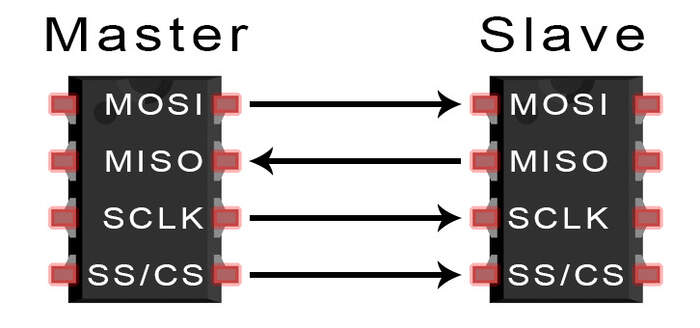
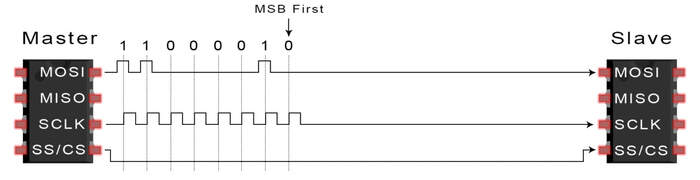
The lines in a SPI communication are as following:
-
MOSI (Master Output/Secondary Input) – Line for the master to send data to the secondary.
-
MISO (Master Input/Secondary Output) – Line for the secondary to send data to the master.
-
SCLK (Clock) – Line for the clock signal which syncronizes the output of data bits from the master to the sampling of bits by the secondary. This is always generated from the master.
-
SS/CS (Secondary Select/Chip Select) – Line for the master to select which secondary to send data to.

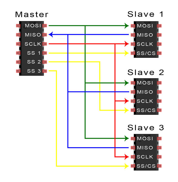
Normally the number of secondaries is limited by the load capacitance of the system, which reduces the ability of the master to accurately switch between voltage levels. To connect multiple secondaries, multiple CS/SS pins have to be available, this are connected to a master in parallel like this:
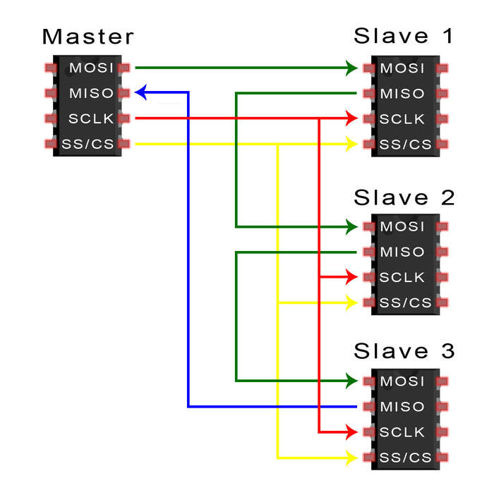
If only one secondary select pin is available, the secondaries can be daisy-chained like this:
How does the SPI work?
-
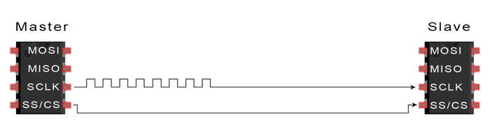
The master outputs the clock signal:
-
Normally, when non transmitting, the SS line is set HIGH. he SPI works by setting the CS/SS line to a low voltage level, this allows the master know which secondary device to send info through the MOSI line to.
-
The master sends the data one bit at a time to the secondary along the MOSI line. The secondary reads the bits as they are received. Data sent from the master to secondary is sent with the most significant bit first:
-
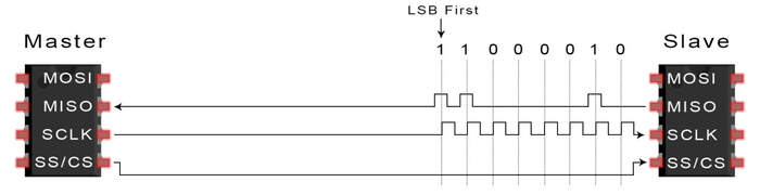
If a response is needed, the secondary returns data one bit at a time to the master along the MISO line. The master reads the bits as they are received, this is done with the least significant bit first.

Advantages of SPI
-
No start and stop bits, so the data can be streamed continuously without interruption
-
No complicated secondary addressing system like I2C
-
Higher data transfer rate than I2C (almost twice as fast)
-
Separate MISO and MOSI lines, so data can be sent and received at the same time
Disadvantages of SPI
-
Uses four wires (I2C and UARTs use two)
-
No acknowledgement that the data has been successfully received (I2C has this)
-
No form of error checking like the parity bit in UART
-
Only allows for a single master
Programming with SPI
-
Many microcontrollers have built-in SPI peripherals that handle all the details of sending and receiving data.
-
The SPI protocol is quite simple so we can write the code without much experience. If using Arduino we use the following commands:
shiftIn()
shiftOut()
-
This is also quite slow so we can also use the SPI library which uses the SPI hardware from the microcontroller. When writing the code it is important to match the following commands to the device (check the device’s datasheet):
-
The interface can send data with the most-significant bit (MSB) first, or least-significant bit (LSB) first. In the Arduino SPI library, this is controlled by the setBitOrder() function.
-
The peripheral will read the data on either the rising edge or the falling edge of the clock pulse. Additionally, the clock can be considered “idle” when it is high or low. In the Arduino SPI library, both of these options are controlled by the setDataMode() function.
-
SPI can operate at extremely high speeds (millions of bytes per second), which may be too fast for some devices. In the Arduino SPI library, the speed is set by the setClockDivider() function.
-
If you’re using the SPI Library, you must use the provided SCK, MOSI and MISO pins, as the hardware is hardwired to those pins. There is also a dedicated CS pin that you can use (which must, at least, be set to an output in order for the SPI hardware to function).
I2C: Inter-Integrated Circuit
I used this link to understand I2C. Sources and figures are from this website.
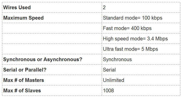
The I2C is becoming popular because it needs less pins than the SPI protocol, whatever number of secondaries you connect to it. It combines both SPI and UARTs: you can have multiple secondaries with a single master and you can have multiple masters controlling one/ or multiple secondaries. This is really useful when you want to have more than one microcontroller logging data to a single memory card or displaying text to a single LCD.
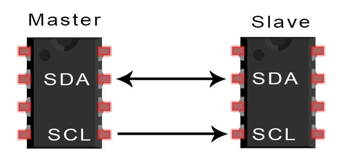
It only uses two wires:
-
SDA (Serial Data) – The line for the master and secondary to send and receive data bit by bit along a single wire.
-
SCL (Serial Clock) – The line that carries the clock signal: as it is synchronous the output of bits is synchronized to the sampling of bits by a clock signal shared between the master and the secondary. The clock signal is always controlled by the master.
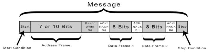
Data is transferred in messages which are broken up into frames of data, each frame data is of 8 bit long. Each message has an address frame that contains the binary address of the secondary device, and one or more data frames that contain the data being transmitted. The message also includes start and stop conditions, read/write bits, and ACK/NACK bits between each data frame:
-
Start Condition: The SDA line switches from a high voltage level to a low voltage level before the SCL line switches from high to low.
-
Stop Condition: The SDA line switches from a low voltage level to a high voltage level after the SCL line switches from low to high.
-
Address Frame: A 7 or 10 bit sequence unique to each secondary device to identify it. The address frame is always the first frame after the start bit in a new message. This is a link to the I2C addresses of the most common sensors and actuators.
-
Read/Write Bit: A single bit inside the address frame specifying whether the master is sending data to the secondary (low voltage level bit) or requesting data from it (high voltage level bit).
-
ACK/NACK Bit: Each frame in a message is followed by an acknowledge/no-acknowledge bit. If an address frame or data frame was successfully received, an ACK bit is returned to the sender from the receiving device and the first data frame is ready to be sent.
How does the I2C work?
-
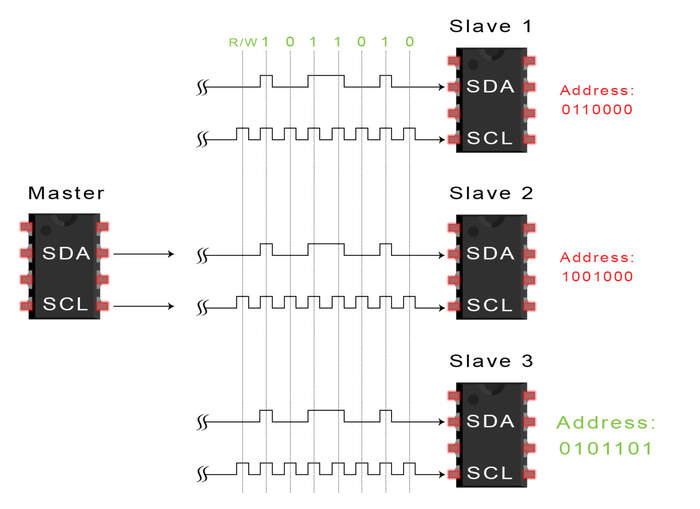
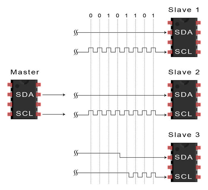
The master sends the start condition to every connected secondary by switching the SDA line from a high voltage level to a low voltage level before switching the SCL line from high to low:

-
The master sends each secondary the 7 or 10 bit address of the secondary it wants to communicate with, along with the read/write bit:
-
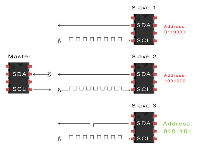
The master sends the address of the secondary device it wants to talk to. Then, each secondary device compares the address sent from the master to their own. If the address matches it sends a low voltage ACK bit back to the master. If the address doesn’t match, the secondary does nothing and the SDA line remains high.
-
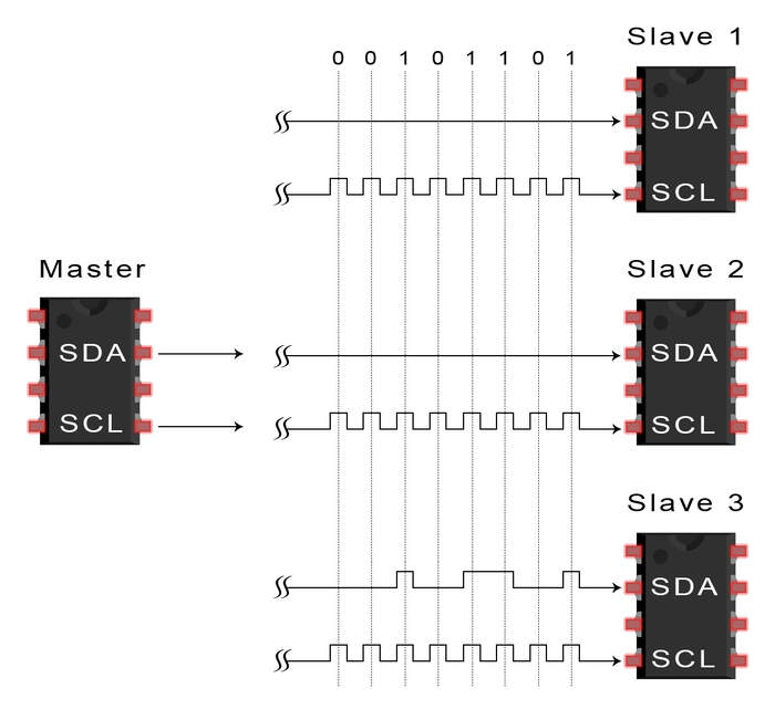
The master sends or receives the data frame:
-
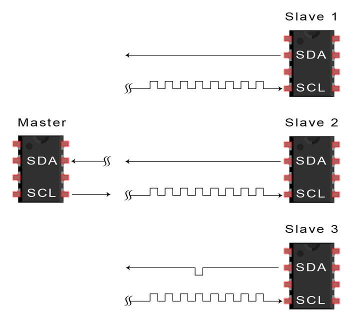
After each data frame has been transferred, the receiving device returns another ACK bit to the sender to acknowledge successful receipt of the frame:
-
To stop the data transmission, the master sends a stop condition to the secondary by switching SCL high before switching SDA high:
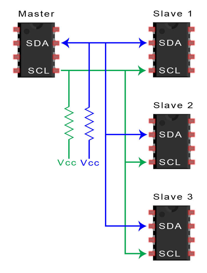
Single master with multiple secondary devices:
- With a 7 bit address, 128 (( 2 ) ^ ( 7 ) = ( 128 )) unique address are available. Using 10 bit addresses is uncommon, but provides 1,024 unique addresses. To connect multiple secondaries to a single master, wire them like the following image, with 4.7K Ohm pull-up resistors connecting the SDA and SCL lines to VCC:
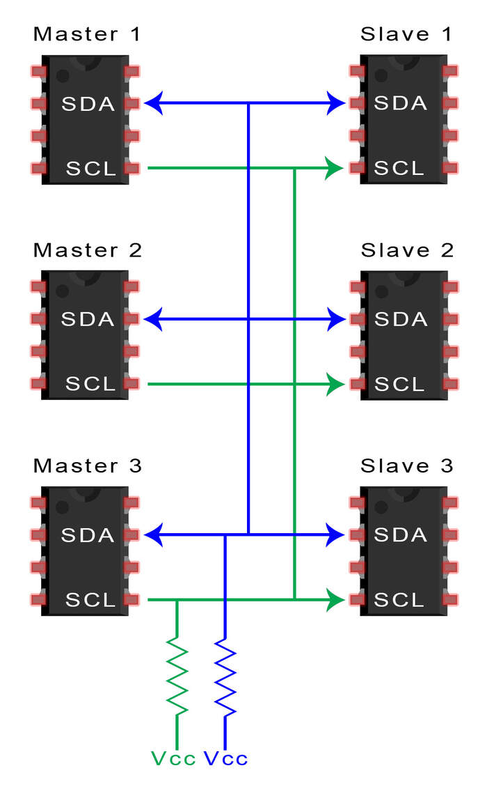
Multiple master with multiple secondary devices:
- The problem with multiple masters in the same system comes when two masters try to send or receive data at the same time over the SDA line. To solve this problem, each master needs to detect if the SDA line is low or high before transmitting a message. If the SDA line is low, this means that another master has control of the bus, and the master should wait to send the message. If the SDA line is high, then it’s safe to transmit the message. To connect multiple masters to multiple secondaries, use the following diagram, with 4.7K Ohm pull-up resistors connecting the SDA and SCL lines to VCC:
Advantages of I2C
-
Only uses two wires
-
Supports multiple masters and multiple secondaries
-
ACK/NACK bit gives confirmation that each frame is transferred successfully
-
Hardware is less complicated than with UARTs
-
Well known and widely used protocol
Disadvantages of I2C
-
Slower data transfer rate than SPI
-
The size of the data frame is limited to 8 bits
-
More complicated hardware needed to implement than SPI
Group assignment: send a message between two projects
Our two group assignments were trying to communicate between three devices, first using I2C and then using asyncronous.
First try using an I2C network:
-
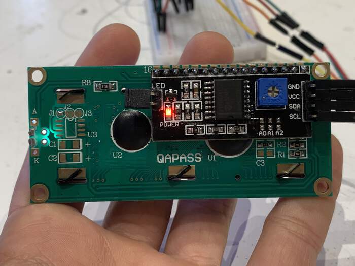
We will try to do an I2C communication network using an Arduino UNO board as the master and an HD44780 LCD display and SDD1306 OLED screen as the two secondary devices.
-
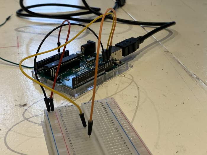
We will be using an Arduino UNO, we have to see which pin is for SCL = pin (we will assign an orange wire) and which pin is SDA (we will assign this a yellow wire). We check them on the pin names from the Arduino UNO board and connect them respectively on the two devices.
-
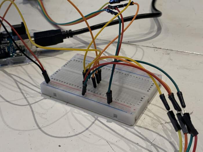
We also connect them in the Arduino UNO with GND(green) and VCC(red) connected to a bread board (which will work as the physical bus and also distributes power from the Arduino to all displays and with SCL and SDA connected on the same line of the breadboard for every device (one is an OLED display and one is an LCD display).
-
The Arduino UNO will be the master and it will communicate everything to the other devices.
-
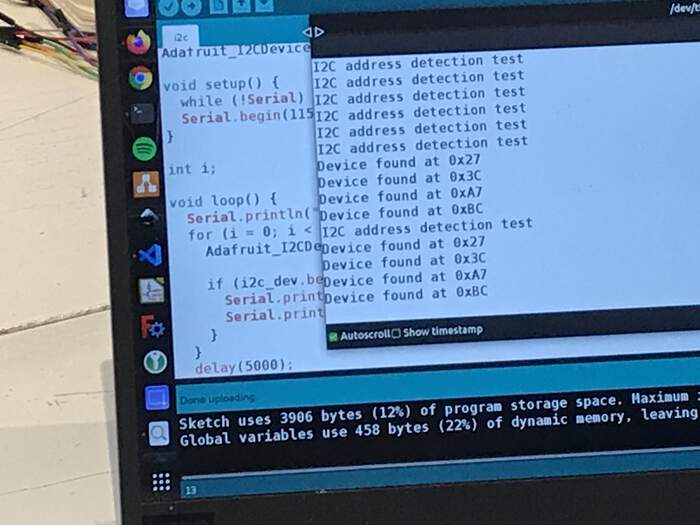
We open Arduino IDE and run I2C address detection test: this is because sometimes the manufacturer doesn’t give the address of I2C device inside the chip. We need to know the address so we run the: Find/Scan address on every device on I2C bus and see which addresses return. Erwin ran the following code:
#include <Adafruit_I2CDevice.h>
Adafruit_I2CDevice i2c_dev = Adafruit_I2CDevice(0x10);

void setup() {
  Serial.begin(115200);
}//void setup

void loop() {
  Serial.println("I2C address detection test");

  // Loop through all possible i2c addresses
  for (char i = 0; i < 127; i++) {
    // Send address
    Adafruit_I2CDevice i2c_dev = Adafruit_I2CDevice(i);

    // If response on address, print address
    if (i2c_dev.begin()) {
      Serial.print("Device found at 0x");
      Serial.println(i2c_dev.address(), HEX);
    }//if
  }//for i
  // Wait 5 seconds, then rescan
  delay(5000);
}//void loop
-
The scan finds four devices: 0x27, 0x3C, 0xA7, and 0xBC, when there are only two connected. Lucia looked into the Internet using a Hex Calculator to understand which one is which. 3C is 60 AND BC is 188, she discovered this with the following equation: 3C = 60(3C) + 128 + 188(BC). So I2C has 128.
-
I learned from this tutorial on hexadecimal system hex is a system used to write and share numerical values. Hex, like decimal, combines a set of digits to create large numbers. It just so happens that hex uses a set of 16 unique digits. Hex uses the standard 0-9, but it also incorporates six digits you wouldn’t usually expect to see creating numbers: A, B, C, D, E, and F. Check more on the link.

-
Then Erwin realised that the 0xA7 is 128 steps beyond 0x27 and 0xBC is 128 steps beyond 0x3C (they were the same addresses).
-
We unplugged the OLED and checked that the address for the OLED was Ox3C, we did the same for the LCD display to check the address was 0x27
-
We spend some time on discussing what the message is that we want to send and we debate the different versions of Arduino.
-
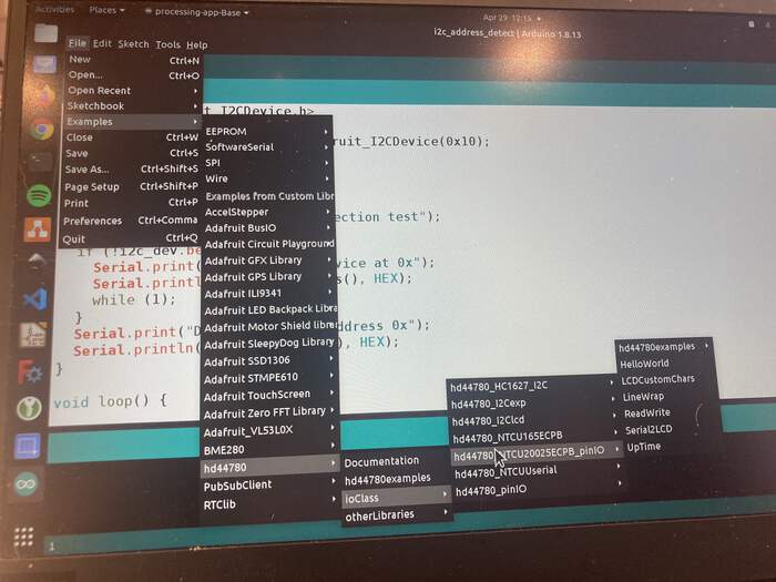
We use two libraries: we start with the LCD display: using the hd44780 library for the Arduino IDE:
-
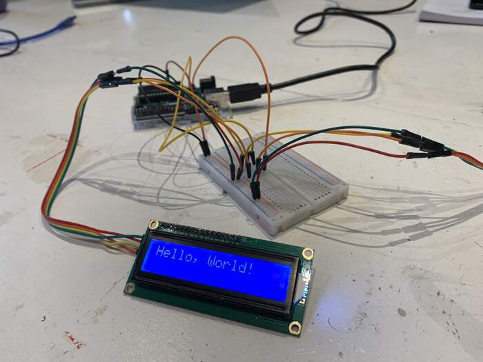
Erwin loaded the Hello World example from the ArduinoIDE (the library we just downloaded). What we do is send bytes to the display over I2C and on the display the local MCU translates this to bytes that are translated to pixels. He used the following code:
#include <Wire.h>
#include <hd44780.h>                       // main hd44780 header
#include <hd44780ioClass/hd44780_I2Cexp.h> // i2c expander i/o class header

//Create LCD object at i2c address You have to specify in the code which address it has to be send to. If you leave this empty it will be send to all displays.
hd44780_I2Cexp lcd(0x27);
//LCDs geometry
const int LCD_COLS = 16;
const int LCD_ROWS = 2;

void setup() {
  int status;

  status = lcd.begin(LCD_COLS, LCD_ROWS);
  if(status) {
    hd44780::fatalError(status); // does not return
  }//if

  // Print a message to the LCD
  lcd.print("Hello World");
}//void setup

void loop() {}
-
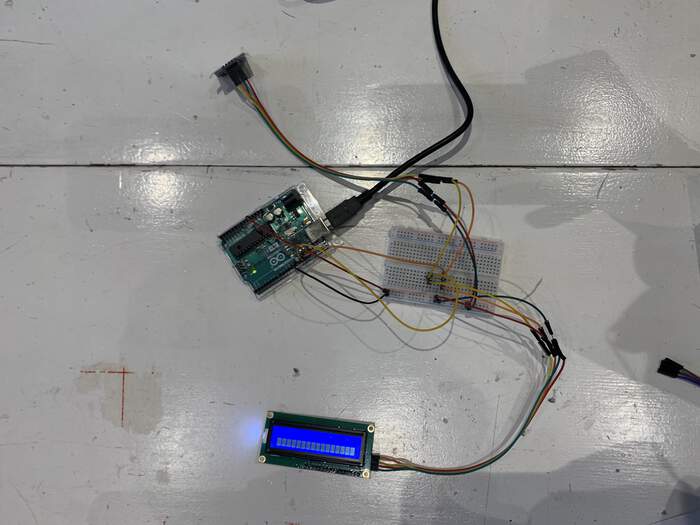
On the LCD screen the display says Hello World:
-
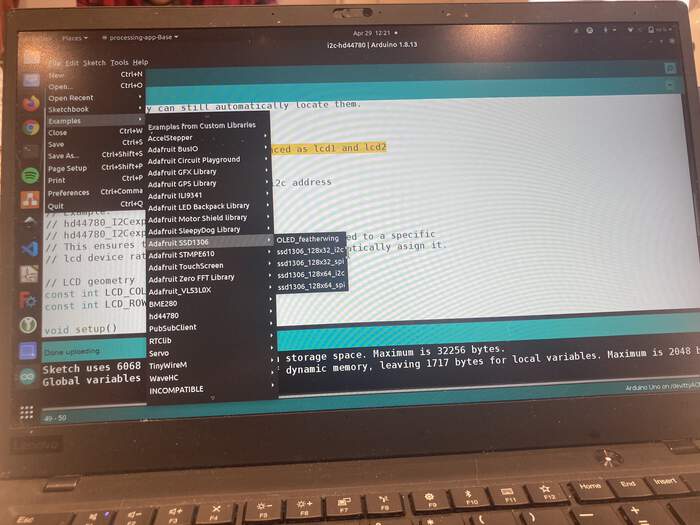
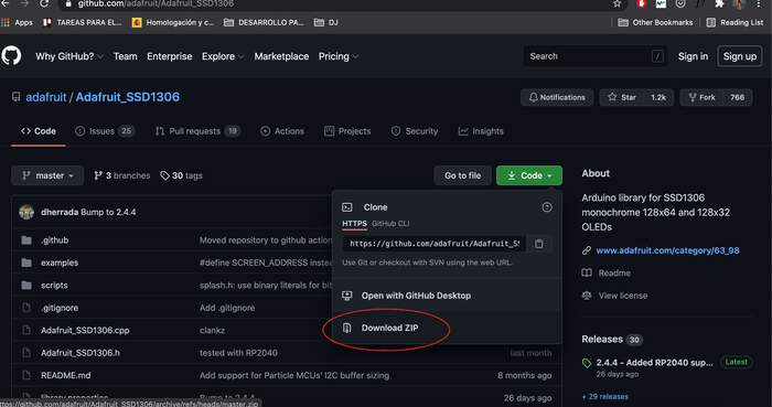
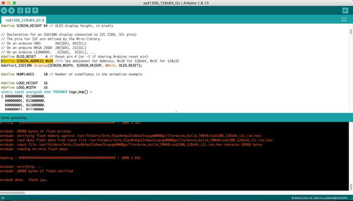
For the OLED display we downloaded the Adafruit SSD1306 library and used the example called: ssd1306_128_32_i2c.
-
The only thing we changed in the code was setting the screen address to:
#define SCREEN_ADDRESS 0x3C
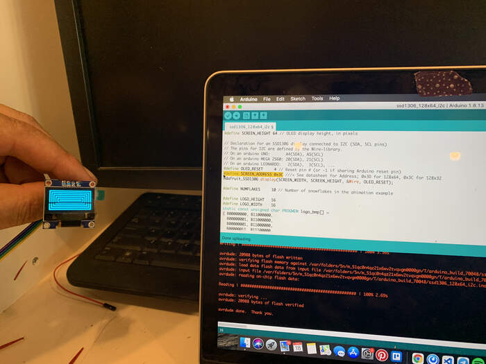
- In the code we first defined the lcd and oled as variables with their addresses, then Erwin copied the libraries and setup code of the LCD into the OLED example(condensing both libraries). He then placed lcd.clear() and lcd.print() statements before each of the changes in the OLED demo, making it show in words what the OLED was showing on the screen. This is part of code:
//Tell the LCD to show the word "Rectangles"
  lcd.clear();
  lcd.print("Rectangles");
  //Two functions from the OLED demo that draw rectangles
  testdrawrect();      // Draw rectangles (outlines)
  testfillrect();      // Draw rectangles (filled)

  //Tell the LCD to show the word "Circles"
  lcd.clear();
  lcd.print("Circles");
  //Two functions from the OLED demo that draw circles
  testdrawcircle();    // Draw circles (outlines)
  testfillcircle();    // Draw circles (filled)
- This is what happened: the LCD display shows what is happening on the OLED screen.
Second try using an asynchronous network:
-
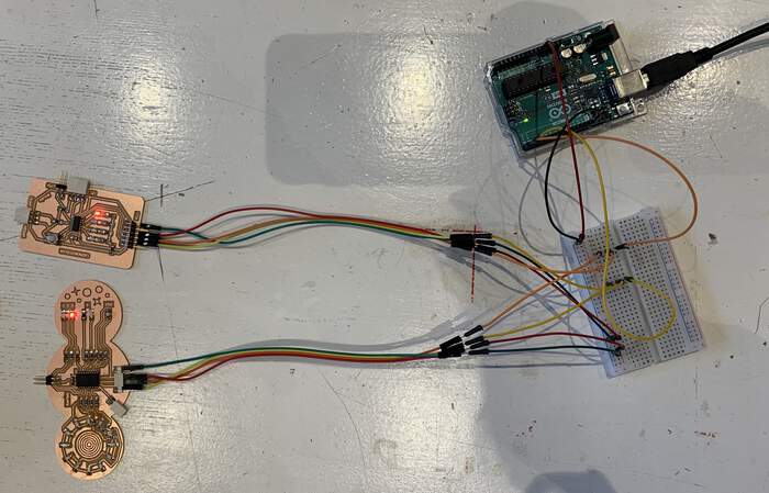
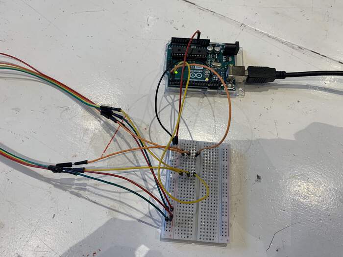
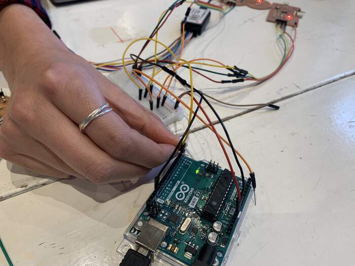
To test out an asynchronous network we connected Nadieh’s board with LEDs with Nichole’s board into the breadboard. These two boards would be the secondary devices. Instead of connecting the SDA and SCL pins (like for the I2C) we used the RX and TX pins from the Arduino board (master device) connecting them to the FTDI of each board. We also connected the VCC and GND like before.
-
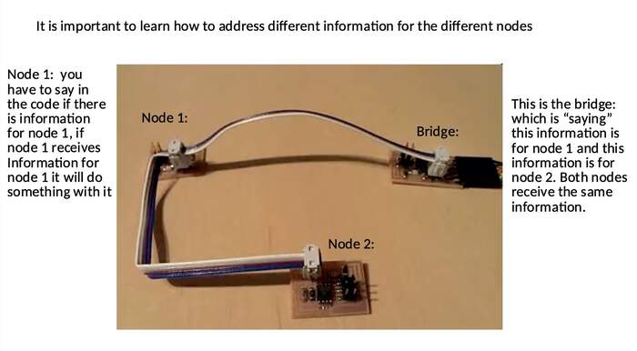
- In this case we are going to need three pieces of code: one for the arduino, and one for both the connected boards: the Arduino code will say something like “THIS message for node 1” and “THIS message for code 2”. The nodes will have each one a code which will say something like “if this code is for you, do what it tells you”.
-
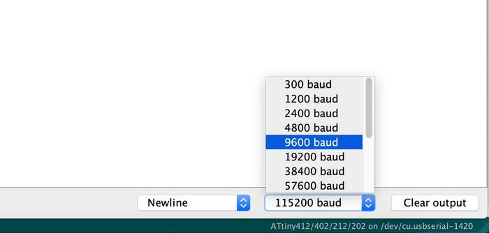
We have to align the speed at which all the boards talk, we choose 9600 baud rate.
-
Erwin wrote the following code for the Arduino, master, to continuously switch between sending something to Nicole’s board (which we defined to be 1) and Nadieh’s board (defined to be 2), with I2C there are defined addresses. But now we have to make addresses. This way the board needs to know who it is speaking to.
/ Define client addresses
#define CLIENT1 1
#define CLIENT2 2

// Define client commands
#define STOP  0x04
#define START 0x08

void setup() {
  Serial.begin(9600);
  pinMode(LED_BUILTIN, OUTPUT);
}//void setup

void loop() {
  // Turn LED off (to indicate client1)
  digitalWrite(LED_BUILTIN, HIGH);

  // Send command START to CLIENT1
  Serial.print(CLIENT1, BIN); // Send address for client 1
  Serial.print(START, BIN);   // Send the command

  // Wait 5 seconds
  delay(5000);

  // Turn LED on (to indicate client2)
  digitalWrite(LED_BUILTIN, LOW);

  // Send command START to CLIENT2
  Serial.print(CLIENT2, BIN); // Send address for client 2
  Serial.print(START, BIN);   // Send the command

  // Wait 5 seconds
  delay(5000);
}//void loop
-
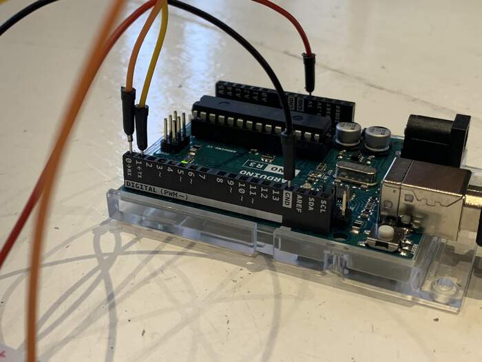
Nothing was uploading to the Arduino, Loes and Nadieh remembered from their machine week that in order to upload a code to the Arduino the two wires from the Arduino of TX and RX had to be disconnected and then reconnected again in order to connect with the two boards.
-
Nadieh programmed the two boards with the corresponding codes of “if this is for me do this”. Erwin gave Nadieh a code that would read any incoming serial data, check if the first bit was the same as the address of the board, if yes, “do something, if not, “do nothing”.
-
Nadieh adjusted the code to turn on the green LED on her board if the incoming data had her board’s address, turn on the red LED if there was something coming in, but wasn’t for her board, and turn on the blue LED if no serial message was being received. In the code of the nodes the only thing you have to change is defining the address of each node/client.
-
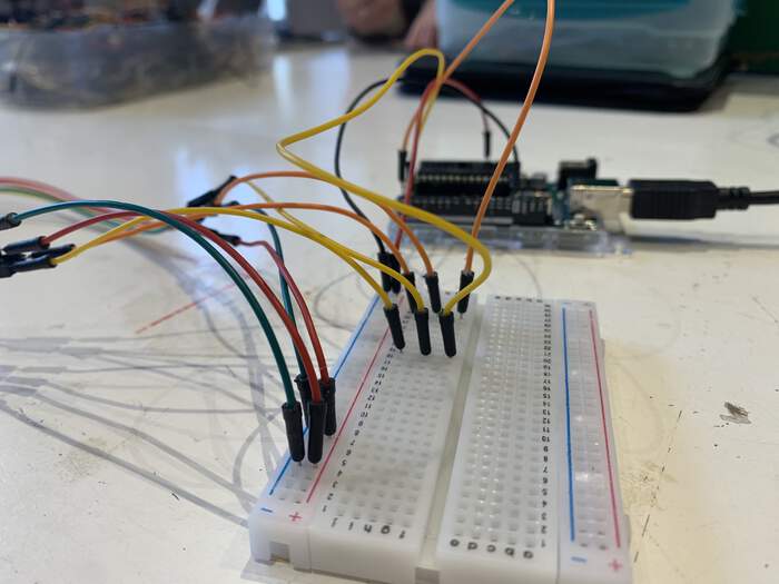
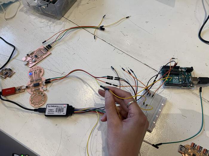
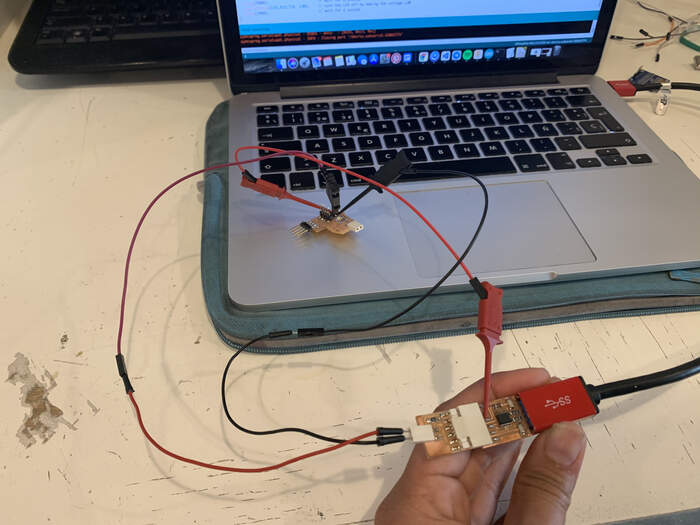
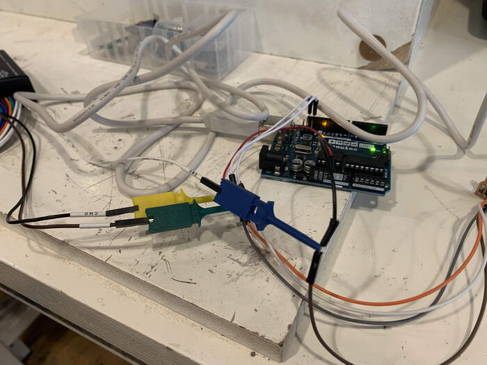
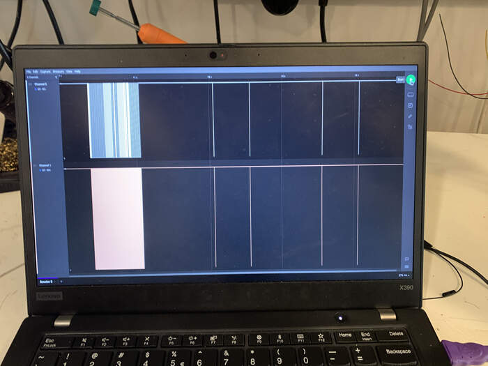
First the blue LED (no serial message being received) showed up constantly. We did not know what was happening so we used a logic analyzer through different parts of the wires and connections to understand what was going on. Nicole connected the logic analyzer to her laptop, plugged channel 6 into the breadboard (along the TX line from the Arduino and RX of the board = yellow wires) and another wire GND from the logic analyzer into GND from the breadboard. We tried to see where the serial message was being lost as the board was not receiving any signal. We try detecting the signal on different parts of the jumper wires:
-
We learned the TX and RX cables were not properly wired (you have to connect the RX to the TX and vcvs).
-
When we changed this the LED on Nadieh’s board turned red, meaning it was receiving serial. She used a delay in the loop function so we could see the red LED blinking because it was over so fast.
-
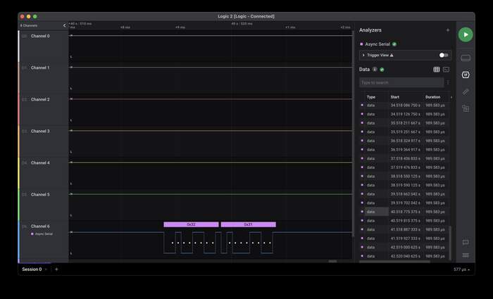
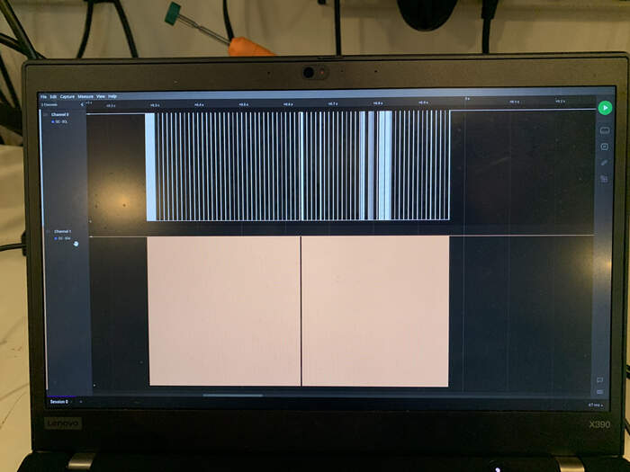
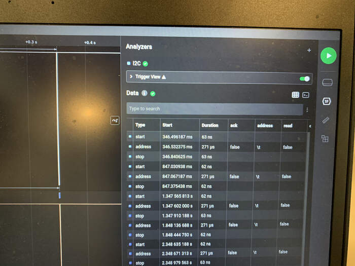
With the logic analyzer we set the Async serial over the channel to decode the bytes, which showed us the incoming bytes that defined the addresses were 0x31 and 0x32, not 1 and 2 as Erwin’s code defined for each client. The logic analyzer showing that the first bytes was 0x32:
-
Then we realised that in hexadecimal, 1 is 0x31 and 2 is 0x32 in hexadecimal. So in the code of Nadieh we defined:
#define myAddress 0x32 (so that the board knew this was its address)
- Nadieh’s board worked!
- Nadieh uploaded the same code to Nicole’s board, changing the address to 0x31 and updating the pin numbers for the red, green, and blue LEDs:
#define myAddress 0x32 //Hardcoded this to be "my" address

#define PIN_LED_R 16
#define PIN_LED_G 0
#define PIN_LED_B 1

void setup() {
  Serial.begin(9600);
  //R, G & B LEDs
  pinMode(PIN_LED_R, OUTPUT);
  pinMode(PIN_LED_G, OUTPUT);
  pinMode(PIN_LED_B, OUTPUT);
}//void setup

void loop() {
  //Reset the pins
  digitalWrite(PIN_LED_R, LOW);
  digitalWrite(PIN_LED_G, LOW);
  digitalWrite(PIN_LED_B, LOW);
  byte incomingByte;

  if (Serial.available() > 0) {
    //Read the incoming byte:
    while (Serial.available()) { incomingByte = Serial.read(); }

    if (incomingByte == myAddress) {
      if (Serial.available() > 0) {
        //Read the incoming byte:
        while (Serial.available()) { incomingByte = Serial.read(); }
        //This is me! Do something
        digitalWrite(PIN_LED_G, HIGH);
      }//if
    } else {
      if (Serial.available() > 0) {
        //Read the incoming byte:
        while (Serial.available()) { incomingByte = Serial.read(); }
        //This isn't me... Do nothing
        digitalWrite(PIN_LED_R, HIGH);
      }//if
    }//else
  }//if
  else {
    //I'm not receiving any serial data
    digitalWrite(PIN_LED_B, HIGH);
  }//else

  delay(1000);
}//void loop
- This made both boards work, showing when data was coming in for each of them:
Individual assignment: design, build, and connect wired or wireless node(s) with network or bus addresses.
This week I will try out I2C communication as I really want to understand how to work with addresses.
I will be making:
-
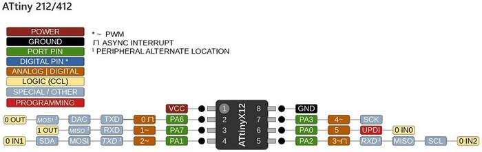
a master board with an ATtiny412 with I2C header pins and a button
-
a secondary board with an ATtiny412, I2C header pins, an LED and connections for an OLED screen.
Master ATtiny412 board: starting to see which components I need:
| Component | Information | Orientation |
|---|---|---|
| ATtiny 412 | Microcontroller_ATtiny412_SSFR | Yes |
| UPDI header | Conn_UPDI_01x02_Male | Yes |
| FTDI header | Conn_FTDI_01x06_Male | Yes |
| Capacitor 1uF | C_1206 | No |
| Button | ? | ? |
| I2C header pins | ? | ? |
I also looked into this student’s documentation for reference.
Secondary ATtiny412 board:
| Component | Information | Orientation |
|---|---|---|
| ATtiny 412 | Microcontroller_ATtiny412_SSFR | Yes |
| UPDI header | Conn_UPDI_01x02_Male | Yes |
| FTDI header | Conn_FTDI_01x06_Male | Yes |
| Capacitor 1uF | C_1206 | No |
| Green LED | LED_1206/160-1167-1-ND | Yes |
| Resistor 1 | 5k for the LED | No |
| I2C header pins | ? | ? |
| OLED screen connections | ? | No |
I also looked into this student’s documentation for reference.
Desiging master board in Ki-Cad
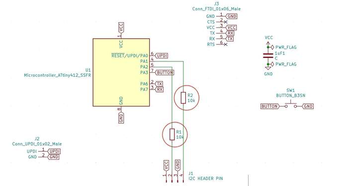
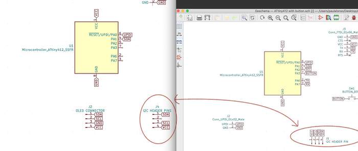
This is how my schematic looked after placing all the symbols and making the connections with labels:
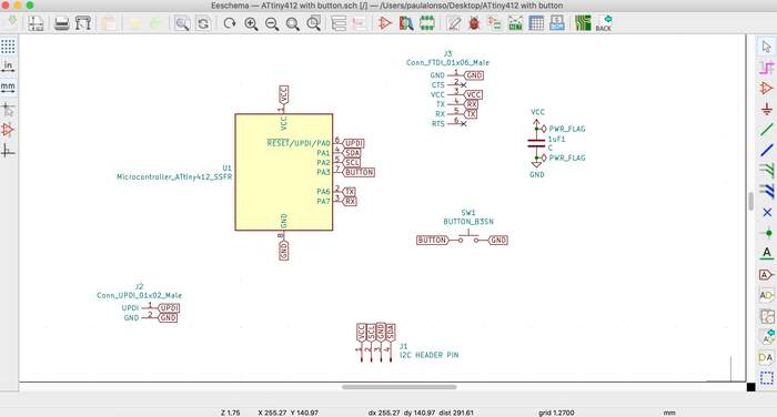
I did all the labels looking at the ATtiny412 Arduino pinout, and taking care I would connect the RX and TX the correct way:
But I still had some questions/doubts to solve on Monday:
-
The VCC and GND pins from the I2C connect the VCC and GND to the other board? Yes, they do. The master board gives power to the secondary board.
-
Does the SDA and SCL need resistors? Cause I saw in the work of this student you did Yes, the SDA and SCL need resistors between the I2C header and the chip. This is how the schematic looked after:
-
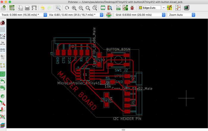
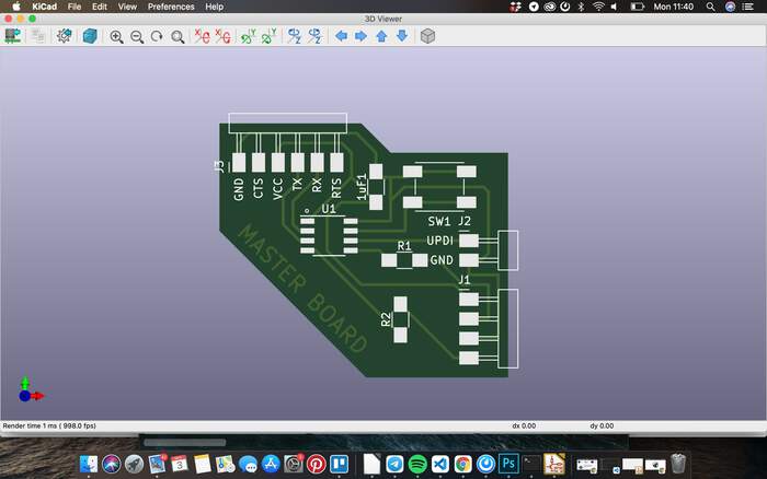
I checked the footprints, annotated everything and went to the PCB layout editor. I added the design rules and started to lay out all the components:
-
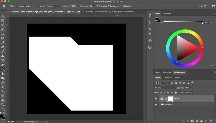
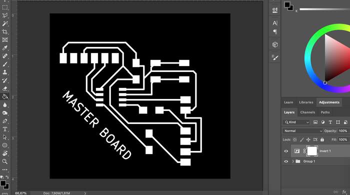
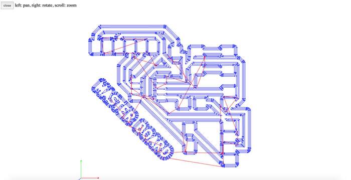
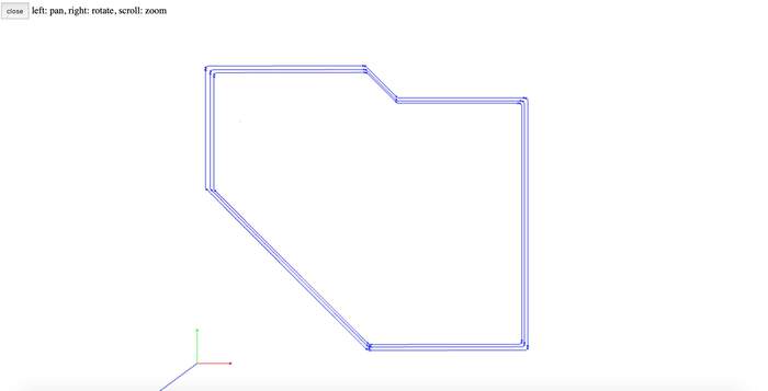
I arranged the two svg’s in Photoshop for the pcb milling machine and check both traces in mods-project, everything seemed ok:
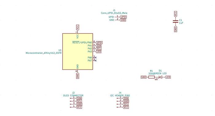
Desiging secondary board in Ki-Cad
I placed all the symbols from the previous table but I still had some questions/doubts to solve on Monday:
-
Does the secondary have to have UPDI? Yes, you have to program the secondary board as well.
-
I believe it should have a FTDI to debug No, it is a simple board so we can work without FTDI.
-
Does the power come from the master board? Yes, it does, through the I2C header.
-
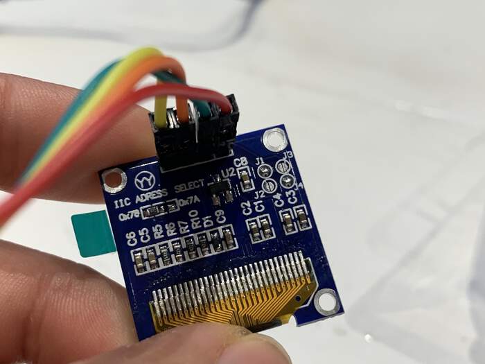
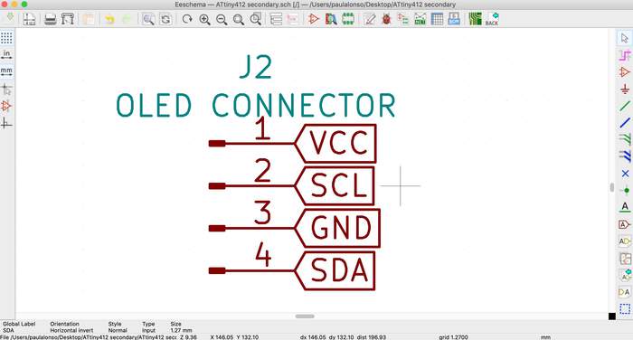
Check the OLED screen we have at the lab and if it needs more connections I checked the OLED screens we have at the lab and I will be using the same as with the group assignment: SDD1306 OLED screen. This OLED screen has 4 connections: VCC, GND, SCL and SDA (as I had already figured out in the schematic).
-
Should I put a female header in the secondary or the same? Are we using wires? Yes, the connection should be the same but with the pins flipped around so that each pins connects to its corresponding, I did this looking at both schematics at the same time so that there were no errors: (it would not be a major error cause I could use jumperwires but it saves a possible mess).
-
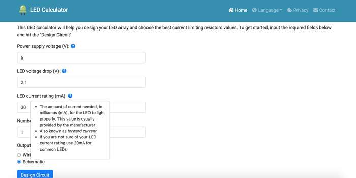
Henk also pointed out the 5K Resistor for the LED was too high and I should calculate it with the LED Calculator.
-
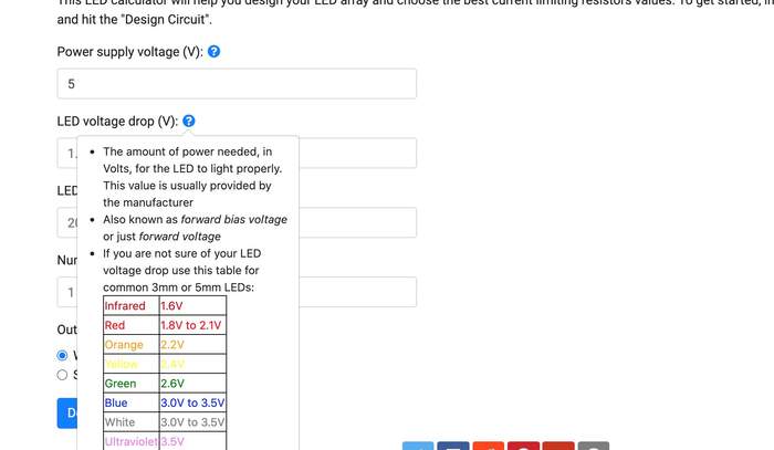
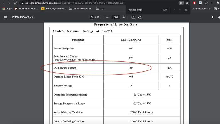
I went to the website and introduced all the data. I got all the values from the LED Datasheet. The Power supply voltage (V) would be 5V as I would be powering it with FTDI with my laptop. I was not sure of the LED voltage drop (V) so I clicked the ? icon and discovered it was also called forward voltage so I looked for this on the datasheet:
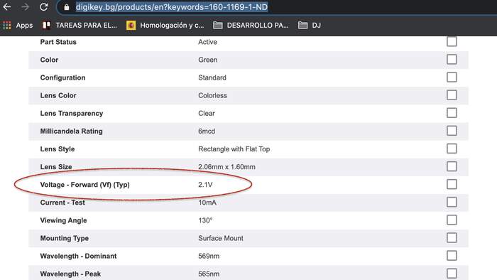
-
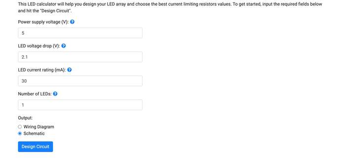
This gave me a value of 2.1 V. Then I had to look for the LED current rating (mA) which I already new it was called DC Forward Current in the datasheet. The value for this was 30mA.
-
The number of LEDS = 1 as I only had one LED on my board. I pressed ok and this was the result:
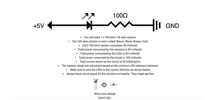
-
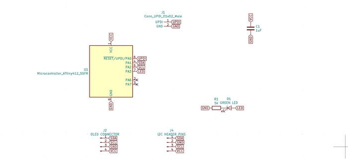
Henk said this might be too low for an LED, Nadieh also recommended that GREEN LEDs needed 320Ω (they were the LEDs with highest resistors from this LED type). I decided to go for the 330Ω resistor as I knew this would be a safe bet.This is how the schematic looked after:
-
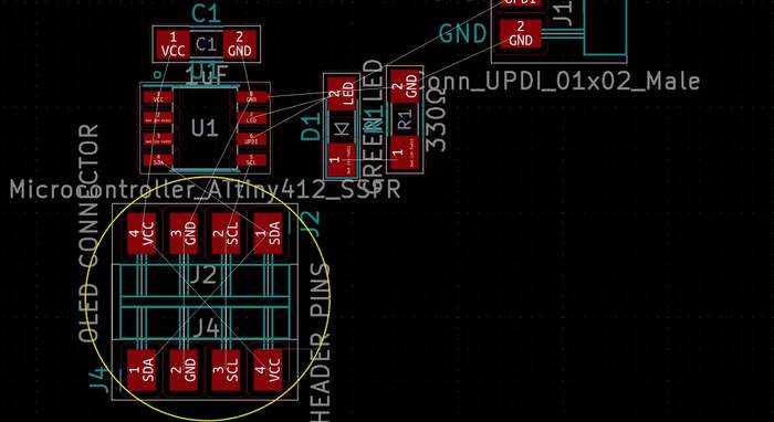
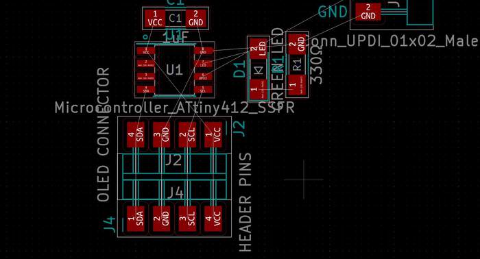
I checked the footprints, annotated everything and went to the PCB layout editor. I added the design rules and started to lay out all the components. I went back to the schematic and changed the order of the OLED pins so that they would be the same as the I2C (for better configuration of the traces). This worked out and made the making of my traces much easier:
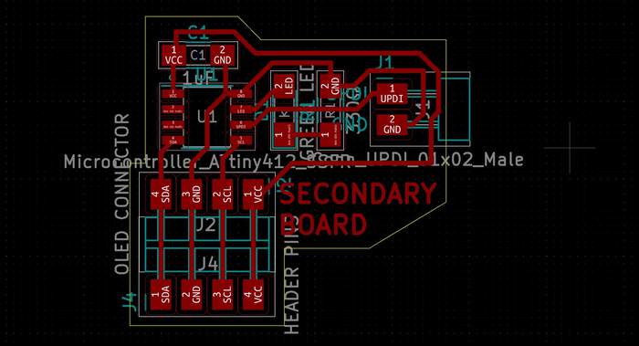
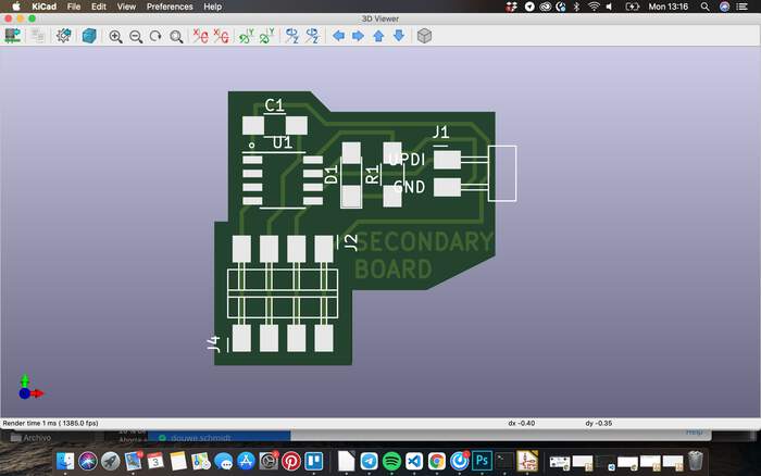
-
I arranged the two svg’s in Photoshop for the pcb milling machine and check both traces in mods-project, everything seemed ok for this board also.
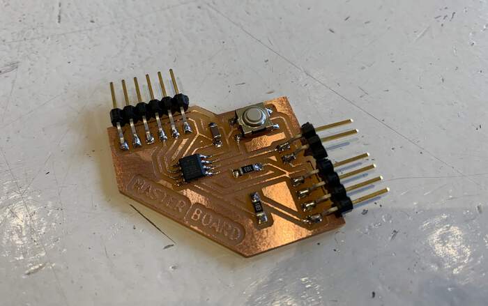
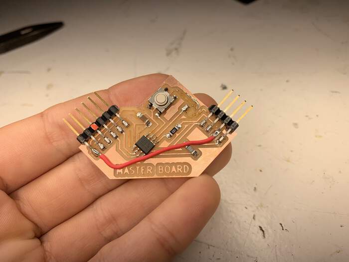
Milling master board
I milled the master board and also soldered it. Everything worked fine:
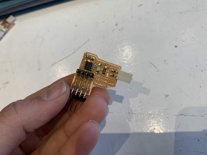
Milling secondary board
I milled the secondary board and also soldered it. Everything worked fine: (I put the wrong UPDI connection by mistake but I just used jumper wires)
Writing code to connect both boards
-
Both boards will be connected through the I2C connection, the OLED is also connected to the secondary board.
-
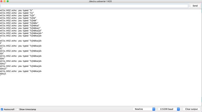
First I will check both of my boards work with the hello echo world code, I first tried uploading it with the master but it would not work, time for debugging…
-
I realised I had put the chip the wrong way around (even though I knew the direction it went), in the process I also figured out the UPDI connection was not properly attached, when trying to attach it the whole pad came of, so I had to do a bypass and I have been program my board with pins attached to the UPDI and GND connection from the chip:
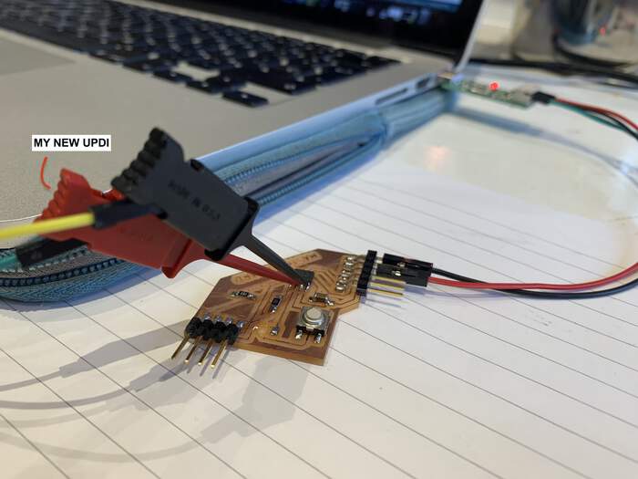
-
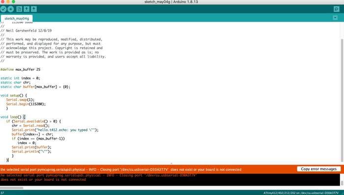
I managed to upload the hello echo world to the master board but when I opened the serial monitor nothing appeared? After trying to debug the board and checking everything was ok. Henk said that maybe we should remove the serial swap from the hello echo world from Neil (because what this does is that it swaps RX and TX for RXD and TXD, the pins you will see in the image below:)
-
When I did this the hello echo world worked in the serial monitor, somehow I think I messed up again the TX and the RX? Ah no! I did it right I just messed up looking at the labels, I have to look at the RX and TX from the pcb that comes from the footprint not at the ones I did with labels(global labels). Reminder for next time :)

-
Now I will connect the secondary through I2C to the master and run the scan devices code to try to detect the OLED, I used the code from this website
// --------------------------------------
// i2c_scanner
//
// Version 1
//    This program (or code that looks like it)
//    can be found in many places.
//    For example on the Arduino.cc forum.
//    The original author is not know.
// Version 2, Juni 2012, Using Arduino 1.0.1
//     Adapted to be as simple as possible by Arduino.cc user Krodal
// Version 3, Feb 26  2013
//    V3 by louarnold
// Version 4, March 3, 2013, Using Arduino 1.0.3
//    by Arduino.cc user Krodal.
//    Changes by louarnold removed.
//    Scanning addresses changed from 0...127 to 1...119,
//    according to the i2c scanner by Nick Gammon
//    https://www.gammon.com.au/forum/?id=10896
// Version 5, March 28, 2013
//    As version 4, but address scans now to 127.
//    A sensor seems to use address 120.
// Version 6, November 27, 2015.
//    Added waiting for the Leonardo serial communication.
//
//
// This sketch tests the standard 7-bit addresses
// Devices with higher bit address might not be seen properly.
//

#include <Wire.h>


void setup()
{
  Wire.begin();

  Serial.begin(9600);
  while (!Serial);             // Leonardo: wait for serial monitor
  Serial.println("\nI2C Scanner");
}


void loop()
{
  byte error, address;
  int nDevices;

  Serial.println("Scanning...");

  nDevices = 0;
  for(address = 1; address < 127; address++ )
  {
    // The i2c_scanner uses the return value of
    // the Write.endTransmisstion to see if
    // a device did acknowledge to the address.
    Wire.beginTransmission(address);
    error = Wire.endTransmission();

    if (error == 0)
    {
      Serial.print("I2C device found at address 0x");
      if (address<16)
        Serial.print("0");
      Serial.print(address,HEX);
      Serial.println("  !");

      nDevices++;
    }
    else if (error==4)
    {
      Serial.print("Unknown error at address 0x");
      if (address<16)
        Serial.print("0");
      Serial.println(address,HEX);
    }
  }
  if (nDevices == 0)
    Serial.println("No I2C devices found\n");
  else
    Serial.println("done\n");

  delay(5000);           // wait 5 seconds for next scan
}
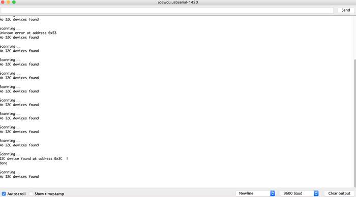
- The scanning device found this:
Scanning...
I2C device found at address 0x3C  !
done
-
Remember to check the baud rate
-
But it only found it once, then it kept on saying it did not find any device.
-
I tried soldering the pins of the OLED to make the conecction more stable but it still gave me the same error.
-
I checked all the connections were OK but they were, couldn’t find the problem. Then I tried using two different OLEDs, one worked (the other two were broken), now it kept giving me an address:
Scanning...
I2C device found at address 0x3C  !
done

Scanning...
I2C device found at address 0x3C  !
done

Scanning...
I2C device found at address 0x3C  !
done

Scanning...
I2C device found at address 0x3C  !
done

Scanning...
I2C device found at address 0x3C  !
done
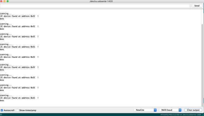
-
So the address of the OLED is 0x3C. The address kept going on and off and we figured out it was because the bypass was not really stable. Henk did a more stable one for the ground trace:
-
But well, after this I can say I have a network:
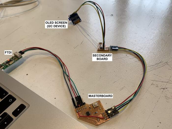
-
After doing the bypass the board stopped working, from the master board to the OLED it would scan the device but from the master board -> secondary board -> OLED it would not read it. We thought the wires were not good but I changed them and it still did not work. I do not know what is hapenning?
-
I then have to make this network do something put a code in the secondary of do this when you are told of and program the master to send a code of if you have this address do this!
-
I then download the Adafruit library for OLED from the group assignment we also used in the group assignment, these were the steps:
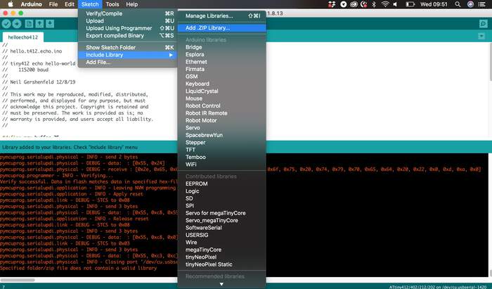
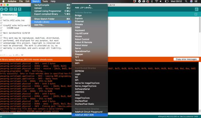
-
After connecting both board and make the code it would not recognize the secondary board, why? Maybe the chip does not have enough memory to hold the wire.h and adafruit library together? Definitely it was the memory what was making the main board not work. So Henk advised me that in order to finish the assignment I had to try an make the secondary board work with the Arduino UNO.
-
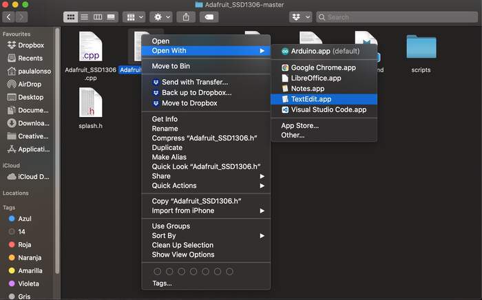
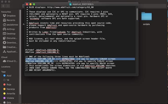
I first connected the Arduino UNO to the OLED to see why it was not working. The problem was that in order to make the OLED work you have to change something from the library Adafruit_SSD1306.h file. I found the file that was saved in my libraries folder and modified it with text edit as you can see below:

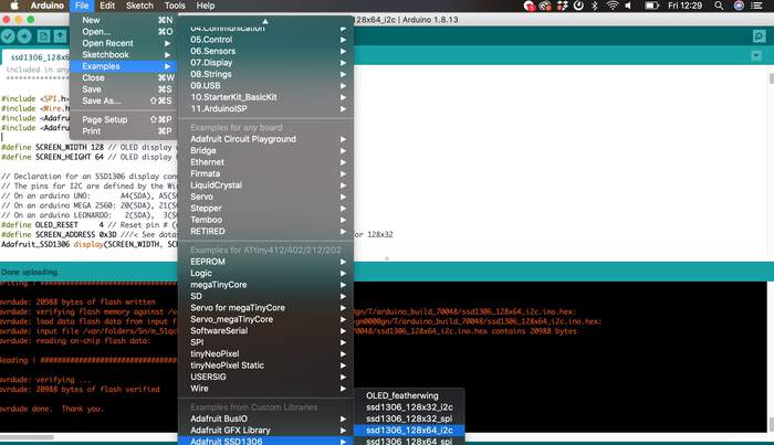
- I then chose the following example code of hello OLED and corresponding port with Arduino Uno:
- Uploaded the code and it started working:
-
I then connected the master board to the Arduino UNO with the I2C and ran the scan device code I used above in my documentation, no device was found.
-
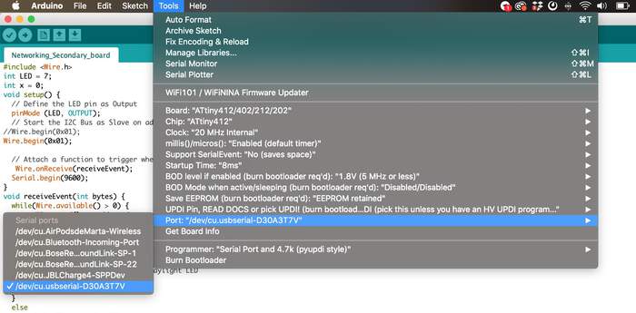
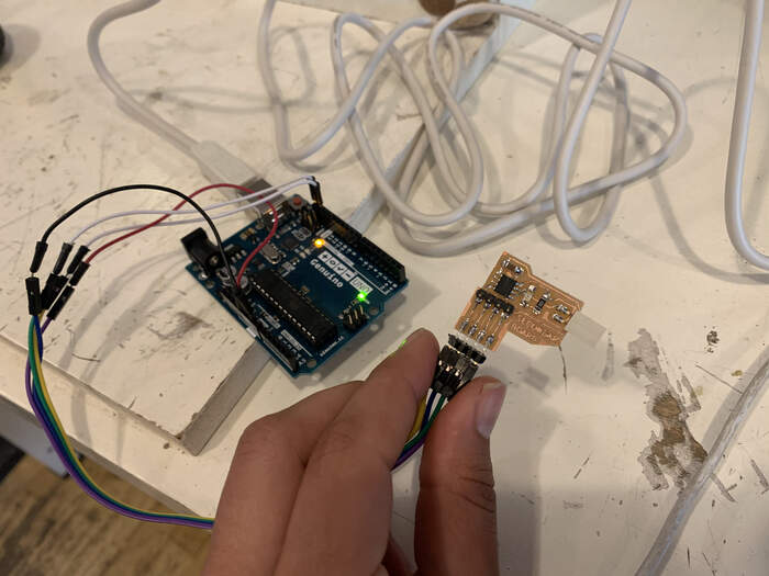
So I then connected the UPDI connecting them directly with the legs from the chips as you can see:
- I connected the VCC of the chip to the VCC from the FTDI connected to the UPDI (which makes a UPDI), then I connected the GND of the chip to the GND of the UPDI and then I connected the UPDI from the chip to the UPDI connection from the UPDI. Loaded the blinking example and it worked:
- Now I will connect the secondary board to the Arduino Uno(removing the VCC from chip to VCC from FTDI connection cause the board will be powered by the Arduino Uno now, and if I don’t there will be a short, also removing the UPDI) through the I2C connection, also attaching the OLED board to the other I2C connection from the secondary board and run the hello world.
Choosing on the Arduino IDE Port the Arduino and chip Arduino Uno this did not work. The OLED screen was black. We connected directly the OLED to the Arduino and in the code the address was not good it was 0x3D instead of 0x3C. We changed this and now it worked.
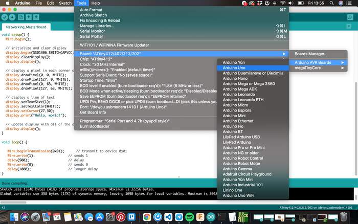
- We now connected the Arduino Uno(this would be the main board) to the secondary board and then to the OLED. And uploaded the OLED code: it worked: the LED was blinking and the OLED screen was turning on:
- Now I had to make a code that addressed the secondary board and said something like “if you receive a 1 print this on the OLED board and blink the LED”, “else: do nothing”. I have to program both master board and secondary board. I found the documentation from Loes very helpful. I modified her code to fit mine. I first uploaded the code to the secondary board:
#include <Wire.h> // library needed for I2C transmission
int LED = 7; // pin on secondary board for LED
int x = 0; // value coming from master board
void setup() {
  // Define the LED pin as Output
  pinMode (LED, OUTPUT);
  // Start the I2C Bus as secondary on address 0x01
Wire.begin(0x01);

  // Attach a function to trigger when something is received.
   Wire.onReceive(receiveEvent); // receives from master board
  Serial.begin(9600);
}
void receiveEvent(int bytes) {
  while(Wire.available() > 0) {
    x = Wire.read();    // read one character from the I2C
    Serial.println(x);
  };
}
void loop() {
  digitalWrite(LED, LOW);
  //If value received is 0 turn off daylight LED
  if (x == 0) {
    digitalWrite(LED, HIGH);
  }
  else
       digitalWrite(LED, LOW);

//delay(500);
  }
- I then uploaded the code to the Arduino Uno as if it was the master board:
#include <Wire.h>

#include <Adafruit_SSD1306.h>

#include <Adafruit_GFX.h>

// OLED display TWI address

#define OLED_ADDR   0x3C

Adafruit_SSD1306 display(-1);

#if (SSD1306_LCDHEIGHT != 64)

#error("Height incorrect, please fix Adafruit_SSD1306.h!");

#endif

void setup() {
  Wire.begin();

  // initialize and clear display
  display.begin(SSD1306_SWITCHCAPVCC, OLED_ADDR);
  display.clearDisplay();
  display.display();

  // display a pixel in each corner of the screen
  display.drawPixel(0, 0, WHITE);
  display.drawPixel(127, 0, WHITE);
  display.drawPixel(0, 63, WHITE);
  display.drawPixel(127, 63, WHITE);

  // display a line of text
  display.setTextSize(1);
  display.setTextColor(WHITE);
  display.setCursor(27,30);
  display.print("Hello, world!");

  // update display with all of the above graphics
  display.display();
}

void loop() {

   Wire.beginTransmission(0x01);      // transmit to device 0x01
   Wire.write(0);                 // sends 0
   delay(500);                    // delay

   Wire.beginTransmission(0x01);      // transmit to device 0x01
   Wire.write(1);                 // sends 1
   delay(1000);                   // longer delay
}
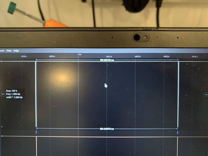
- I then connected everything together, the LED kept on as well as the OLED screen, there were no different values coming in ? strange. I connected the board to the logic analyzer to see why the LED would not turn off:
- I could see how signals were coming in:
- Changed both codes after seeing this link
Master code:
// Include the required Wire library for I2C<br>
#include<Wire.h>

#include <Adafruit_SSD1306.h>

#include <Adafruit_GFX.h>

// OLED display TWI address

#define OLED_ADDR   0x3C

Adafruit_SSD1306 display(-1);

#if (SSD1306_LCDHEIGHT != 64)

#error("Height incorrect, please fix Adafruit_SSD1306.h!");

#endif

int x = 0;

void setup() {
  // Start the I2C Bus as Master
  Wire.begin();
  // initialize and clear display
  display.begin(SSD1306_SWITCHCAPVCC, OLED_ADDR);
  display.clearDisplay();
  display.display();

  // display a pixel in each corner of the screen
  display.drawPixel(0, 0, WHITE);
  display.drawPixel(127, 0, WHITE);
  display.drawPixel(0, 63, WHITE);
  display.drawPixel(127, 63, WHITE);

  // display a line of text
  display.setTextSize(1);
  display.setTextColor(WHITE);
  display.setCursor(27,30);
  display.print("Hello, world!");

  // update display with all of the above graphics
  display.display();
}

void loop() {
  Wire.beginTransmission(9); // transmit to device 0x01
  Wire.write(x);              // sends x
  Wire.endTransmission();    // stop transmitting
  x++; // Increment x
  if (x > 5) x = 0; // `reset x once it gets 6
  delay(500);
}
Secondary code:
// Include the required Wire library for I2C
#include <Wire.h>
int LED = A3;
int x = 0;
void setup() {
  // Define the LED pin as Output
  pinMode (LED, OUTPUT);
  // Start the I2C Bus as Slave on address 9
  Wire.begin(9);
  // Attach a function to trigger when something is received.
  Wire.onReceive(receiveEvent);
}
void receiveEvent(int bytes) {
  x = Wire.read();    // read one character from the I2C
}
void loop() {
  //If value received is 0 blink LED for 200 ms
  if (x == 0) {
    digitalWrite(LED, HIGH);
    delay(500);
    digitalWrite(LED, LOW);
    delay(500);
  }
  //If value received is 3 blink LED for 400 ms
  if (x == 3) {
    digitalWrite(LED, HIGH);
    delay(500);
    digitalWrite(LED, LOW);
    delay(500);
  }
}
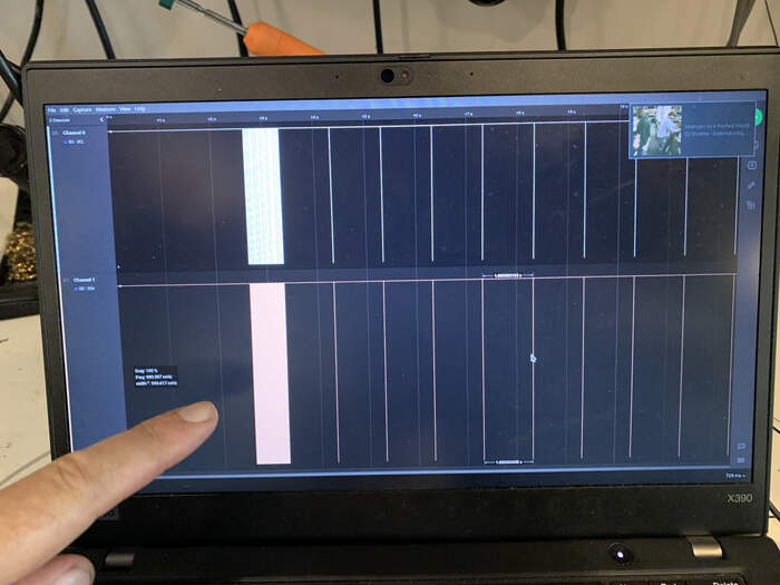
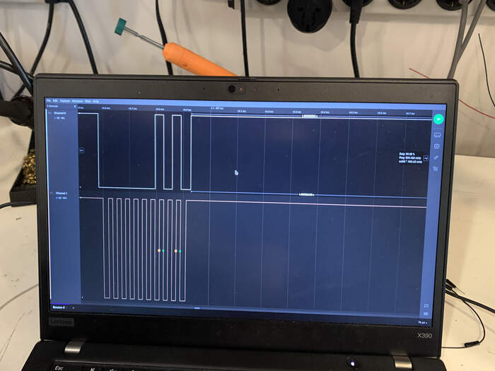
- I could see that if I changed things in the code they would appear in the logic analyzer, experimented loads of things on the code but it never turned off the LED. here for example I modified the delay to 500 and I could see it in the logic analyzer:
- If I changed the wire write value it would change things on the address part of the logic analyzer so it was receiving the signal:
- The different thing with this new code was that it blinked but very lightly. I had a network cause I could see it working in the logic analyzer but couldn’t figure out why I could not visibly see the LED turning off
Because this week has only worked through the Arduino UNO how would I improve on the design in order to make it functional? I would use another ATtiny chip with much more memory so that all the libraries fit. The ATTiny 3216 would be a good option as it has more memory than the one I used.
Files to this week’s assignments:
-
This is the Ki-CAD schematic file in PDF for the master board | kicadschm
-
This is the Ki-CAD schematic file in PDF for the secondary board | kicadschs
-
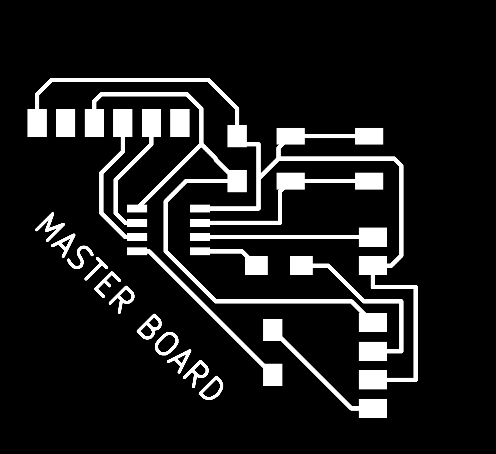
This is the traces PNG for the master board | tracesmaster
-
This is the interior PNG for the master board | interiormaster
-
This is the traces PNG for the secondary board | tracessecondary
-
This is the interior PNG for the secondary board | interiorsecondary