This and next week is a group assignment only:
| Assignment | Used software | Files/Downloads/links |
|---|---|---|
| slots for ketchup extractor | FreecAD | slot.fcstd |
| housing for ketchup extractor | Inkscape | tubeblock+holders_6mm.svg |
| code for the machine | arduino-ide | machine.ino |
| tube extractor test code | arduino-ide | test-code.ino |
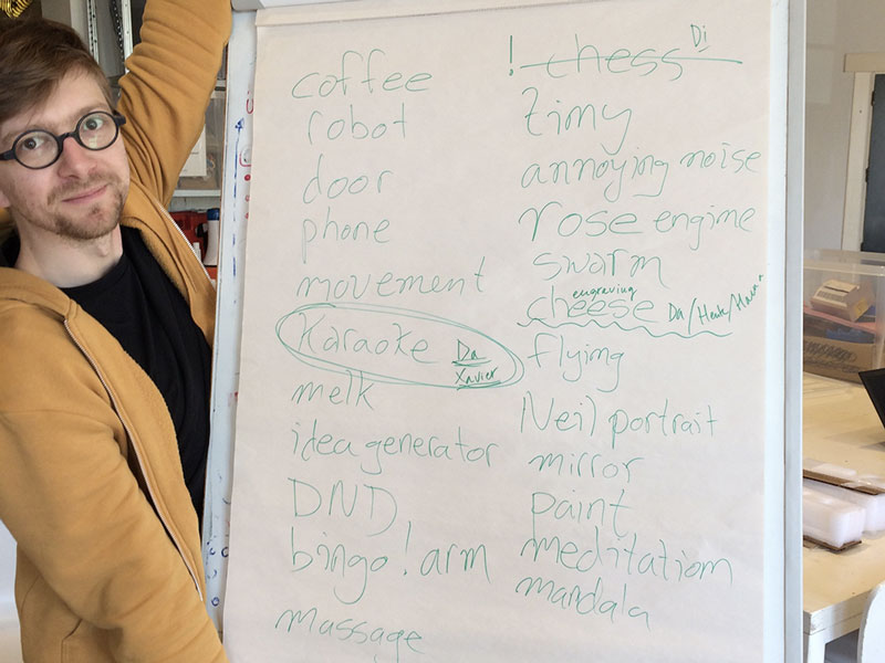
Since we are a big group in Amsterdam, we decided to create two teams. First, we brainstormed in the big group to later decide the two smaller groups. Very early in the brainstorming session, we noticed that we all wanted to do something silly and fun, not necessarily the most useful machine. Ideas like a karaoke machine, Neil bingo, and engraving cheese with a Rose Engine came up. One idea stuck a bit more: It was the Dutch lunch generator. If you have ever been in the Netherlands, you know that Dutch people many times eat sandwiches for lunch. What they put on the sandwiches differs from chocolate, minced raw meat, cheese, etc. Johanna, Henk, Jelka, and Hanna decided to go ahead and create a random Dutch lunch generator.
We where inpired by the The queen of shitty robots. Our Dutch Lunch Machine transports a 'boterham' along four stations with typical Dutch toppings like: 'hagelslag', 'muisjes', 'chocopasta' and off course 'peanut butter'. Let's also add a video of a Rose Engine, just for inspirations sake.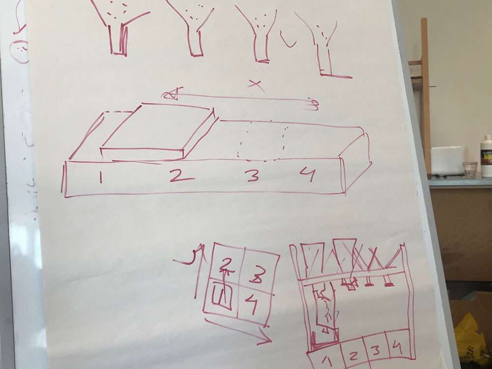
The machine will help you decide the topping on your sandwich, randomly, and in combinations that you might otherwise wouldn't have thought of. The bread piece will be placed in a lunchbox that is already standing under the different toppings. Exactly how the random generator will start is not decided yet, but the idea is that a motor will act accordingly to code that is randomizing the different sections of the stage and then opening up the respective funnel that is stopping the topping from coming out.
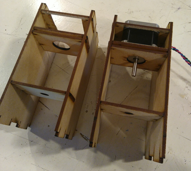
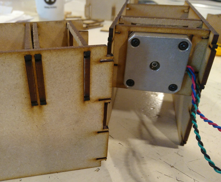
We decided to divide the work between us; Johanna was going to build the stage, Jelka the construction over the stage, the housing, holding up the topping funnels, Henk would create a construction that could turn tubes so that we could have some tube toppings as well, and Hanna would create the construction for the topping funnels and their respective motor.
Before starting designing the stage, Johanna had a look at some of the previous student's work. Emma had also shown us a modular system for stages. However, we decided fairly early that we wanted to work with MDF, and the folding versions of stages would only work with cardboard. As a reference we used the files of the machine that Fab Lab Facens made in 2017. They had made a design in MDF that looked similar to what we wanted to do. They also had a downloadable version of their design. It included the drawings for the x-axis module we wanted to use.
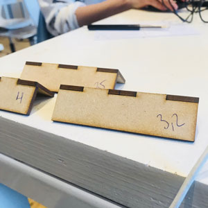
Johanna downloaded the file and started making some changes in Illustrator. The team had decided on some measurements for the machine, and for some reason, she must have gotten them really wrong. However, we didn't notice this until much later when the stage was cut and assembled. Which resulted in Hanna and Jelka re-doing the design when Johanna was away in Stockholm. We still love Johanna anyway. Blessing in disguise, she got to help when she got back since the file had minor mistakes and we also decided to make a few tweaks to it.
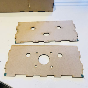
 The wrong holes for linear bearing
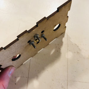 Attached
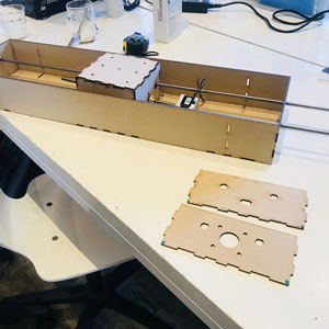
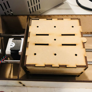 In place
 Glued to stay in place
 Assembled-ish
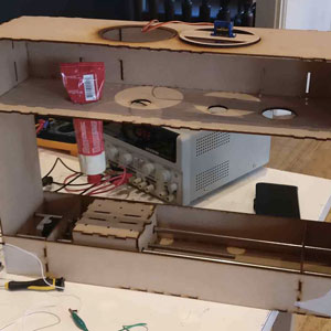 Assembled-ish
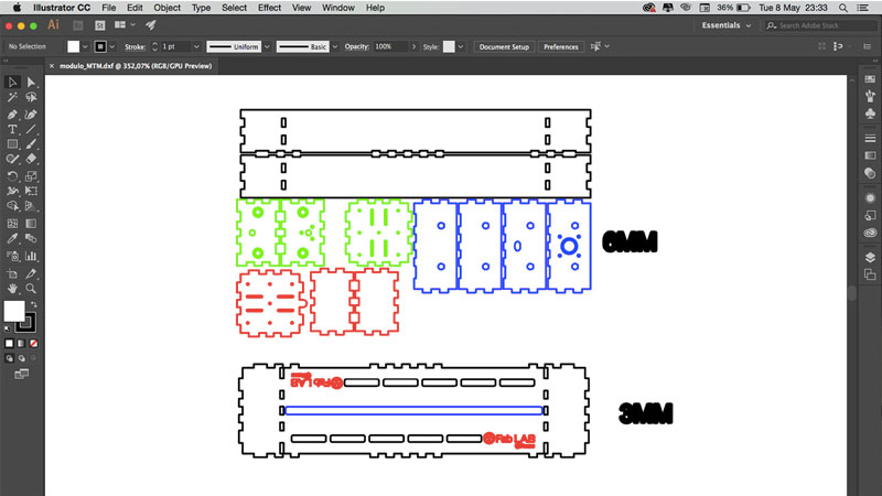
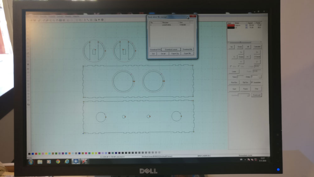
When Hanna had arranged the dimensions we wanted, Jelka used the file to draw the pilars and the upper part that holds the toppings. Hanna had used cm's in her drawing and when Jelka opened the file in Fusion, it was in mm's. So Jelka scaled the file 10x. The way to do this is right click the sketch in the browser and choose edit sketch. Then in the toolbar in the top of the page left click the arrow with the Sketch icon and choose Sketch scale. Jelka drew the pilars, or height panels, the upper parts that hold the tubes and the reservoires for the toppings. You can download Jelka's fusion file here. The password is FabAcademy2018. Please keep in mind that it has a mistake in the slots of the 'height' panels. They should me 3,2mm instead of 6,4mm. In the picture below you can see what is what. The parts that have comments on them in red are the ones Jelka drew.

Here you can download the Illustrator file here and the dxf files here.
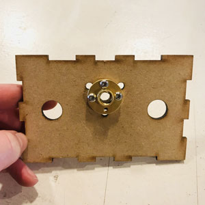
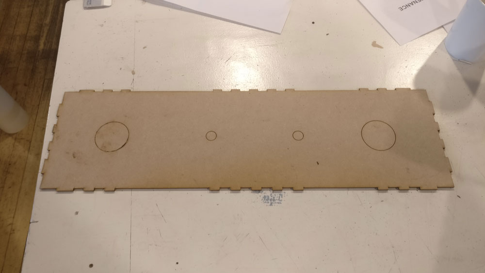
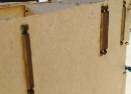
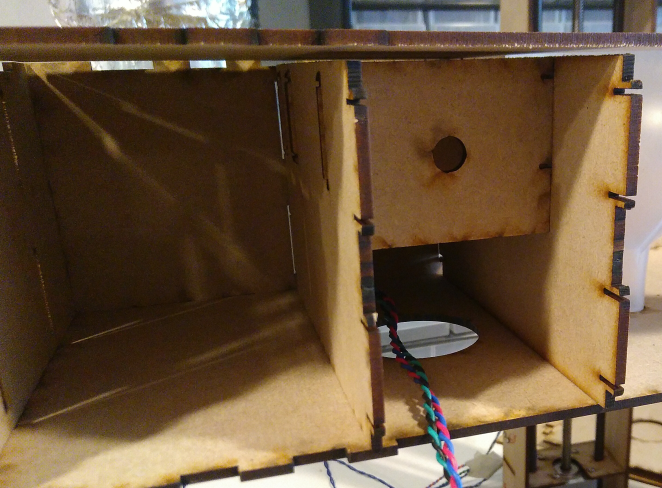
Hanna designed the funnels. They have to be able to open and and close to let the hagelslag out. Also the need to be fixed somehow in the upper part of the machine. She wanted the funnels and the closable lid to nicely sink in the MDF, so she engraved both the edges half way. Unfortunately this left a really thin edge of MDF for lids, so she left that at 3mm. The picture below shows the settings for cutting and engraving the funnel holes and the lids.
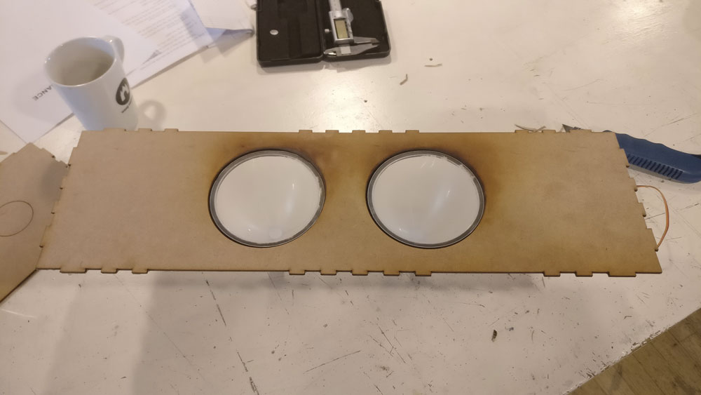
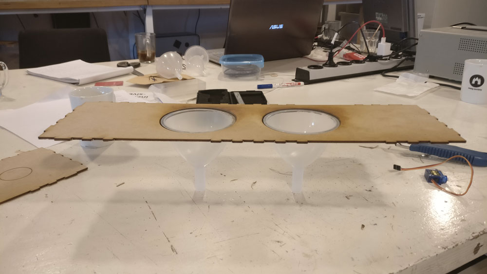
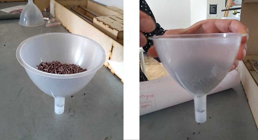
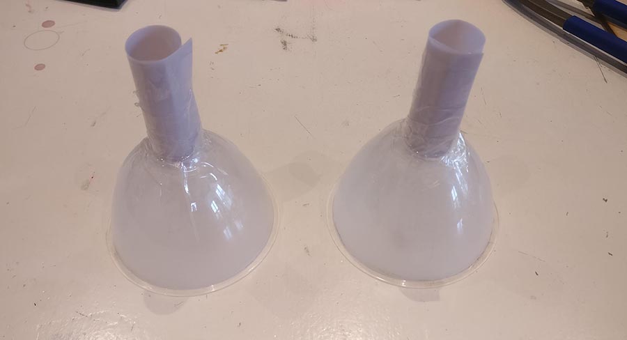
However, when we tested the funnels with chocolate sprinkles we discovered that the funnel opening was too narrow and the sprinkles got clogged. Hanna fixed this by cutting away the bottom part of the funnel and attaching a wider tube to it.
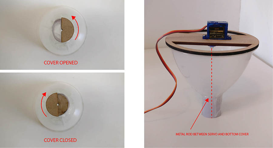
Hanna also designed a system for opening and closing the funnels with servo motors to control the amount and timing of the food deposition. Below is the photo showing the mechanism. The cover closing the funnel is attached with a metal rod to the motor.
For our machine Henk designed the tube extractor.
Things Henk wanted to learn this week:
At the end he should have a tube extractor for our machine. And because images say more than words, and because of fun, he will show the final result:
So as you can see, a tube extractor extracts in this case ketchup out of a tube. It’s done by using a steppermotor. The motor rotates half a revolution and so extruding the ketchup out of the tube.
The motor is in a housing Henk will design this week.
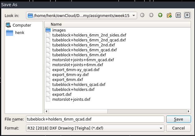
He did the main design in inkscape. The pressfit with joint he made in freecad, because it was the most complex part, that he also wanted to make parametric.
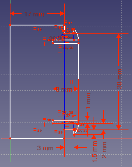
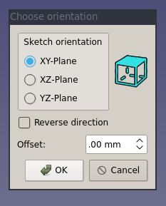
After making the part fully constrained, he had problems exporting it to dxf. The part came out as a flat line. So after some guessing, he figured out it had to do with the orientation of the plane used in freecad. So he had to change planes. It took him a while to figure out where to do it in freecad. It finally found it under parts design menu.
The file was exported to dxf and then imported in inkscape. Inkscape however give an error when importing dxf files from freecad.
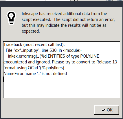
So again he used qcad to open the dxf and save it in another dxf format.
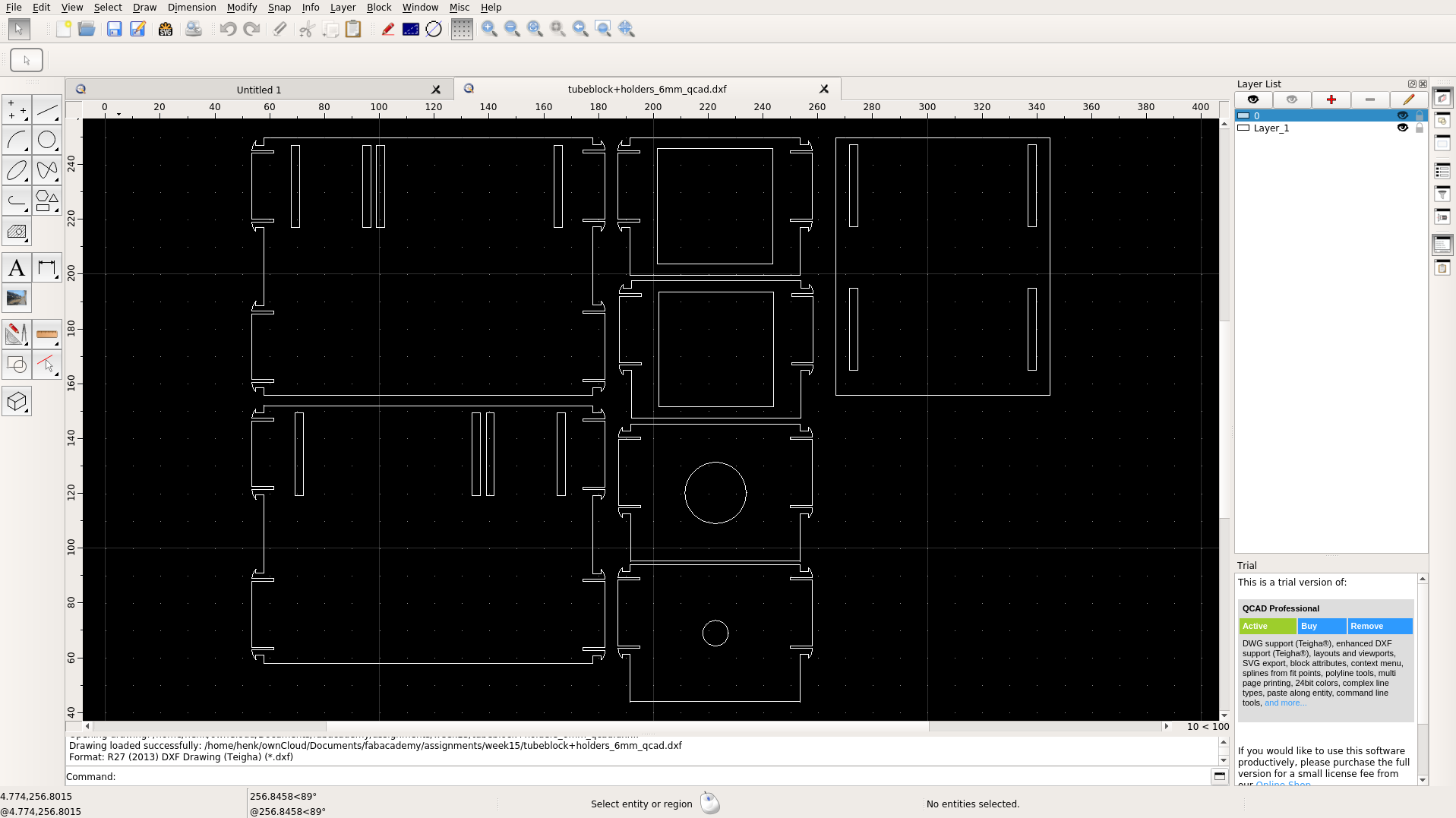
Not listening to errors (who needs them anyway!) he saved the design in DXF R32 format. That on imported fine to inkscape.
Here is the design he made:

Continuing the group assignment
In this assignment we are allowed to use arduinos to run our machine. We were going to use an Arduino Uno with a Arduino CNC Shield to run the three stepper motors (the Arduino CNC Shield has room for four). The two server motors for the funnels will be connected directly to pins on the Arduino.
This site explains really well why you want to set the current limitation on the stepper motor. It says: “To achieve high step rates, the motor supply is typically much higher than would be permissible without active current limiting. For instance, a typical stepper motor might have a maximum current rating of 1 A with a 5Ω coil resistance, which would indicate a maximum motor supply of 5 V. Using such a motor with 12 V would allow higher step rates, but the current must actively be limited to under 1 A to prevent damage to the motor.” To set the current limit we used a power source, a multimeter and a small screwdriver. In our case the power source was broken, so we had to use an extra multimeter to measure the voltage from the power source. To set the current limitation you trim the potentiometer or the board. Johanna and Henk did this together since someone has to look at the multimeter and someone to hold the multimeter and make sure not to create any shorts. We set the three potentiometers to 0.8 V as to referred to David’s calculations. Something was very wrong when doing this, the multimeter went down to zero everytime we did the measurement. We figured that something must be wrong with the hardware, and after a while Johanna saw that one of the jumpers were broken. We replaced it and now it worked fine.
We had gotten some example code from Emma that we tried out to see if we could run the three motors at the same time.
#define EN        8

//Direction pin
#define X_DIR     5
#define Y_DIR     6
#define Z_DIR     7

//Step pin
#define X_STP     2
#define Y_STP     3
#define Z_STP     4


//DRV8825
int delayTime=30; //Delay between each pause (uS)
int stps=6400;// Steps to move


void step(boolean dir, byte dirPin, byte stepperPin, int steps)

{

 digitalWrite(dirPin, dir);

 delay(100);

 for (int i = 0; i < steps; i++) {

   digitalWrite(stepperPin, HIGH);

   delayMicroseconds(delayTime);

   digitalWrite(stepperPin, LOW);

   delayMicroseconds(delayTime);

 }

}

void setup(){

 pinMode(X_DIR, OUTPUT); pinMode(X_STP, OUTPUT);

 pinMode(Y_DIR, OUTPUT); pinMode(Y_STP, OUTPUT);

 pinMode(Z_DIR, OUTPUT); pinMode(Z_STP, OUTPUT);

 pinMode(EN, OUTPUT);

 digitalWrite(EN, LOW);

}

void loop(){

 step(false, X_DIR, X_STP, stps); //X, Clockwise
 step(false, Y_DIR, Y_STP, stps); //Y, Clockwise
 step(false, Z_DIR, Z_STP, stps); //Z, Clockwise

 delay(100);

 step(true, X_DIR, X_STP, stps); //X, Counterclockwise
 step(true, Y_DIR, Y_STP, stps); //Y, Counterclockwise
 step(true, Z_DIR, Z_STP, stps); //X, Counterclockwise

 delay(100);

} (edited)
CNC - research and code is done by Henk.
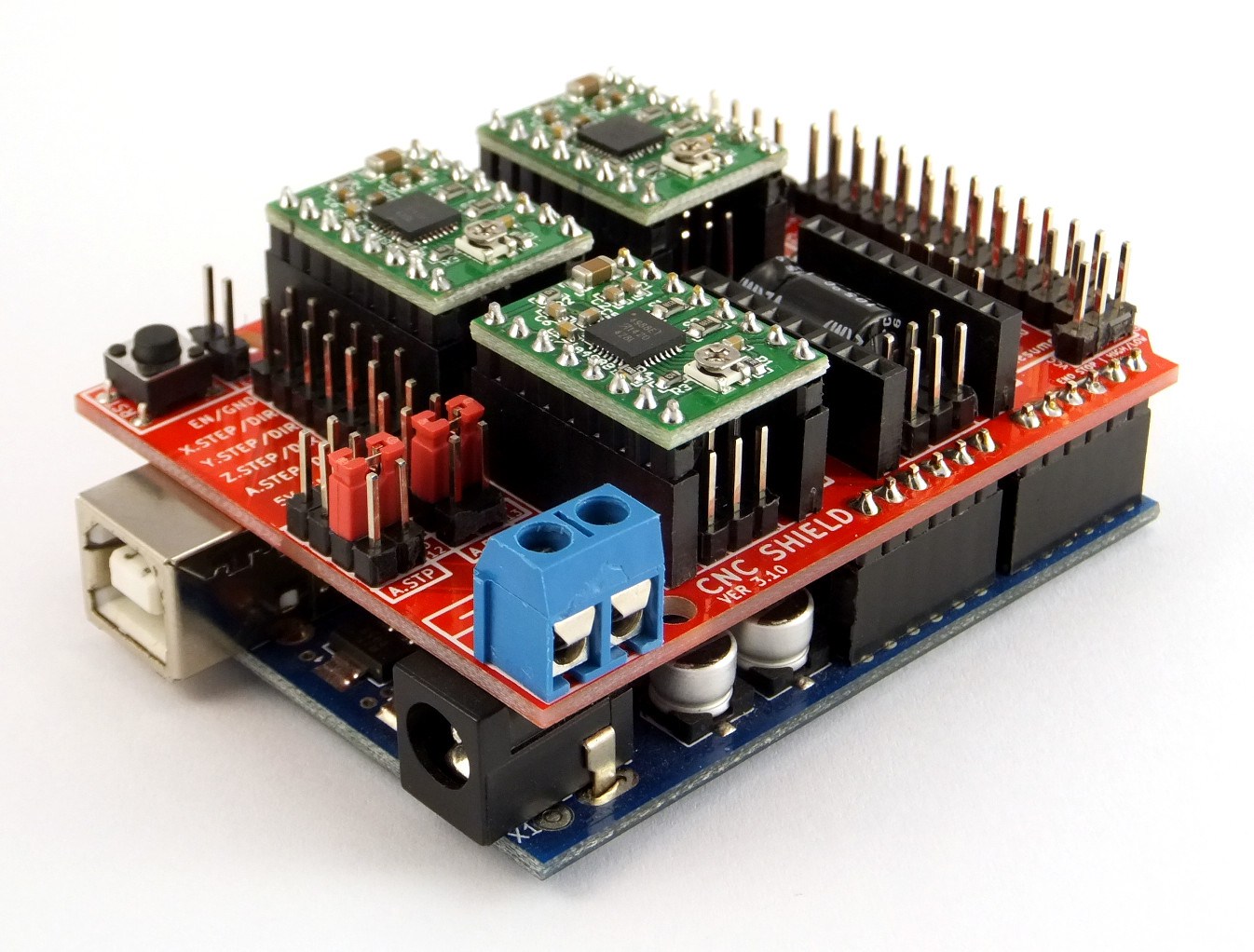
For the machine we use 3 “DRV8825 Stepper Motor Driver Carrier, High Current” shield to drive the stepper motors. They are attached to the Protoneer Arduino CNC Shield. This CNC-shield fits on a arduino uno.
The programming is done on the arduino, so to understand what pin is needed for the project, we used these 3 images to get an overview. The first on is the scheme of the cnc shield. The shield we started with already had 3 DRV8825 shields on top. We used position X, Y and Z. The A position was not used. On the right sight of the shield were the connectors (4pins) to plugin the wires for the 3 steppermotors. Under each DRV8825 shield are 6 pins positions named MO, M1 and M2. We connected them all with jumpers to get 1/32 microsteps per step (so 200*32=6400) for a complete revolution. Our stepper has 200 steps per revolution. I didn’t mention that before :)
| MODE0 | MODE1 | MODE2 | Microstep Resolution |
|---|---|---|---|
| Low | Low | Low | Full step |
| High | Low | Low | Half step |
| Low | High | Low | 1/4 step |
| High | High | Low | 1/8 step |
| Low | Low | High | 1/16 step |
| High | Low | High | 1/32 step |
| Low | High | High | 1/32 step |
| High | High | High | 1/32 step |
Another pin we used was the enable pin, to activate the motors, which is probably the E-Stop location on the scheme.
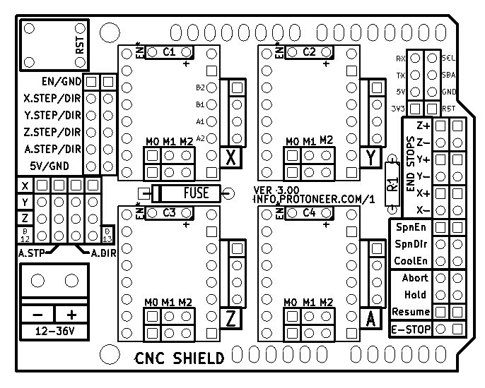
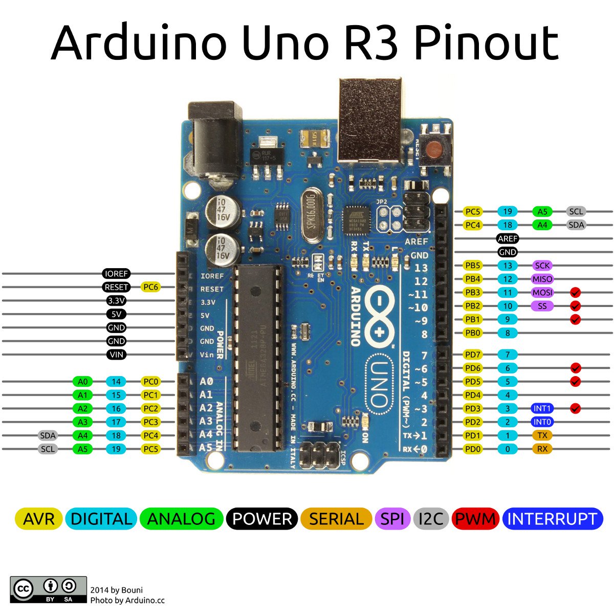
By reading the next image we could figure out what pins were connected. Digital 2-13 are all connected to the CNC shield. But, in our case, we only used D2-8. The analoge pins A0-A3 are also connected and used. Pin A4 and A5 are not used.
We were looking how to connect the button, to get a topping on you sandwich, and the 2 servos we needed for the funnels.
For the button it was quite easy. We used pin A5, because it was free.
To connect the 2 servos was more complicated because we thought that these servos needed to be connected to PINs with PWM functionality. From the arduino pinout below we knew that PWM is only available on pin D3, D4, D5 and D9, D10, D11. So the only pins we could use for the servos are D9 and D10 (and D11 also).

#define EN        8      //Negative Enable pin
#define X_DIR     5      //Direction pin
#define X_STP     2     //Step pin

int delayTime=80; //Delay between each pause (uS)
int stps=6400;// Steps to move microsteps 1/32 (200*32 = 6400)
void step(boolean dir, byte dirPin, byte stepperPin, int steps) {

  digitalWrite(dirPin, dir); //

  for (int i = 0; i < steps; i++) {
    digitalWrite(stepperPin, HIGH);
    delayMicroseconds(delayTime);
    digitalWrite(stepperPin, LOW);
    delayMicroseconds(delayTime);
  }
}
void setup(){
  pinMode(X_DIR, OUTPUT); //direction pin = output
  pinMode(X_STP, OUTPUT); //step pin = output
  pinMode(EN, OUTPUT); //negative enable pin  =output
  digitalWrite(EN, LOW); //start negative enable pin at low
}
void loop(){
	step(true, X_DIR, X_STP, 3200); //true equals back towards motor
 	delay(2000);

 }
I wrote this script to test the tube extractor. And it’s working.
I connected the steppermotor to the X-position of the DRV8825 shield on the CNC shield. I put together this code:
 - defining all connections to the X_DIR- and STP (and don't forgot the negative ENABLE pin).
 - copied the code for the motor settings
 - setup function for the pinmodes

 loop:
 - do a half revolution and then rest for 2 seconds.
go to the beginning of this page for a full description of the shields and pins or continou reading from here as in the next chapture i explain the code we used for the machine.
But first an impression of the working test code and the tube extractor:
Till now i only copied programms, removed bits i didn’t need and declared the pin numbers i used. So this was my first proper programm. I didn’t use the functions till now. Everything fitted in the setup or loop. So this week i learned a bit how to use them. A thing i liked is that it gives a better overview of the code, separating complexities in functions. Other things i used before but didn’t really understand where the “#declare”, “for” and “int”, so the “values (variables and constants)”.
In this explained of the code we wrote, i try to explain what i think they all do.
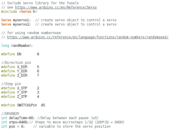
The beginning of the code starts with a couple of includes and variables.
The first block handles the include of a servo library and the variables of the 2 servos we use for the funnels. If you want to know more read the page of the servo library. We called the 2 servos myservo1 and myservo2.
Then follows a line that has to do with the random nummers we use for the stages. Long variables are extended size variables for number storage.
Pins for working with the cnc-shield are declared in the next block, followed by the pinnumber for the button. At this section on shields and pins you can see the schematics and explanation of the pins that we use in this code.
Last in this block are variables for the steppermotors. A revolution of the stepper consists of 200 steps. With the DelayTime you give the amount of delay after 1 step. So the higher the delay, the longer a revolution will last, in other words: the less delay the higher the speed of a revolution. STPS handles the microsteps per step. On the CNC-shield we used jumpers to set it to 1/32 microsteps per step. So a complete revolution (stps) will be 200*32=6400 microsteps.
Going through the arduino references i noticed this description of #define. Next program i’m gonna try to use const….
#define is a useful C component that allows the programmer to give a name to a constant value before the program is compiled. Defined constants in arduino don’t take up any program memory space on the chip. The compiler will replace references to these constants with the defined value at compile time.

This can have some unwanted side effects though, if for example, a constant name that had been #defined is included in some other constant or variable name. In that case the text would be replaced by the #defined number (or text).

In general, the const keyword is preferred for defining constants and should be used instead of #define.
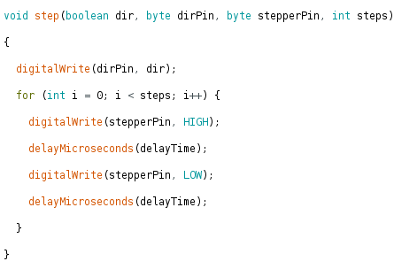
For the void-step():
To be honest we copied the first function from a arduino code we got from Emma. It handles the way how it will write LOW and HIGH according to the (micro-)steps and timedelay between the steps we handled in the first block. Anyway: it’s doing what it supposed to do :)
I will emma ask later on for an explanation.
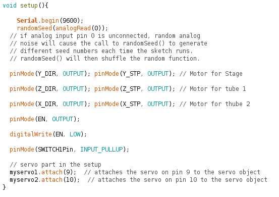
For the void-setup():
The setup() function is called when a sketch starts. Use it to initialize variables, pin modes, start using libraries, etc. The setup() function will only run once, after each powerup or reset of the Arduino board.
For debugging serial is enabled.
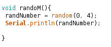
Next comes a line to activate the randomseed(). Arduino reference for randomseed.
If it is important for a sequence of values generated by random() to differ, on subsequent executions of a sketch, use randomSeed() to initialize the random number generator with a fairly random input, such as analogRead() on an unconnected pin.
We used pin A0 for this, because it’s not used in our sketch.
After that we set the modes for the different pins. For the stepper it are all OUTPUTS, only for the button we used the pin as INPUT_PULLUP, meaning this pin is HIGH and when pushed puts the pin in a LOW state.
Last the servo pin are declared in the setup (pin D9 and D10), see this section on shields and pins.
The void loop() is pretty clean. Put in word:
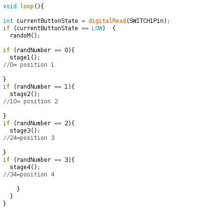
The void randoM() is the function that picks a random number between 0-4. So Random numbers are 1, 2 and 3.
The last functions are the 3 stages/positions.
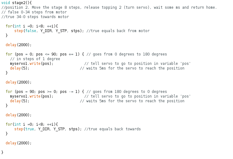
First it activates motor Y connected to the stage. With a “for” statement it uses steps to go to the right position. In this case it does <8 steps, so it counts from 0 till <8 which is 7, in total 8 steps.
When it is in position is delays for 2000ms.
On top of this position hangs a funnel driven by the first servo. The servo opens the funnel by going from position 0 to 90 in 90 steps delayed by 5ms. This opens the funnel.
This open funnel is delayed by 2000ms, the hagelslag/chocolate prinkles are falling down.
Now the servo closes the funnel by doing the opposite as above.
The funnel is now closed again and delays again to catch also the latest fallen hagelslag/chocolate prinkles.
Now the stepper motor Y is going back home, same as above, but in thee opposite direction.
When home, 2000ms delay, before it goes again in the loop function, starting over the whole process.
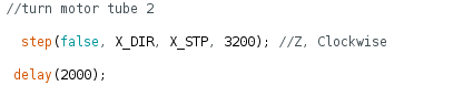
The other stages are activating the other servo (position 3) and another stepper that is emptying the tube (position 4).
The code used for the tube only does a half revolution, that should be enough for the ketjup to be pushed out.
A lot! Trying to read code is different than really understand code! Till now i was able to read code and fiddle a bit around with it. I now have a better understanding of the code.
First Hanna assembled the system for closing the funnels. She discovered that that the connection between the metal rod and mdf half circles has to be redesigned to make it more stable. She added a circular extension to the centre of the half circle where the metal rod could go through, so that it would be held in place when turning. (Right photo below)

Then Hanna found and adjusted a sweep code for servo motor for opening the cover 180 degrees with the speed of 5ms between every 1 degree step and 2000ms pause after opening and closing:
	//sweep code for turning servo 180 degrees and back

	#include

	Servo myservo;  // create servo object to control a servo
	// twelve servo objects can be created on most boards

	int pos = 0;    // variable to store the servo position in degrees

	void setup() {
	  myservo.attach(9);  // attaches the servo on pin 9 to the servo object
	}

	void loop() {
	  for (pos = 0; pos <= 180; pos += 1) { // goes from 0 degrees to 180 degrees, in steps of 1 degree
	    myservo.write(pos);              // tell servo to go to position in variable 'pos'
	    delay(5);                       // waits 5ms between each degree for the servo to reach the position (speed of the shaft)
	  }

	delay(2000);

	  for (pos = 180; pos >= 0; pos -= 1) { // goes from 180 degrees to 0 degrees
	    myservo.write(pos);              // tell servo to go to position in variable 'pos'
	    delay(5);                       // waits 5ms between each degree for the servo to reach the position (speed of the shaft)
	  }

	delay(2000);

	}
Then Hanna tested the code first with the empty funnel to check how the cover opens and closes:
And after that also with sprinkles:
When the system was working more or less fine Hanna attached the funnels onto the machine.
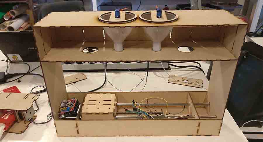
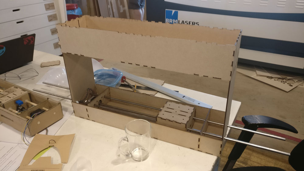
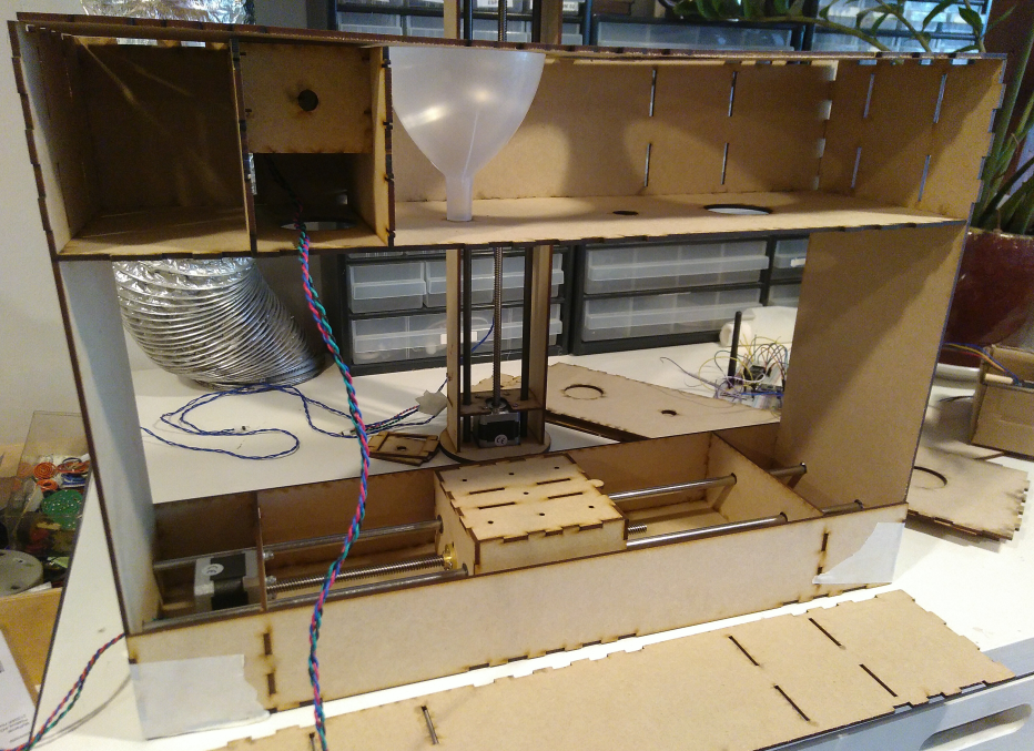
After we had tested the funnels and the tube system we were ready to assemble and wire the whole machine. Jelka re-wired the Arduino to the inside of the machine. First she took a picture of how everything was connected. Then she used tie wraps to attach the Arduino to the machine and some more tie wraps to hold the wires. Later Henk also put a duct tape. Emma really wasn't happy with the wiring, so Jelka improved her work on this. She soldered the wires to the red button instead of using alligator clips. She made some of the wires shorter and led them to the hole in the middle panel.


When the wiring was done, we could also really assemble the machine. We had some trouble with fitting in the big motor for the ketchup tube. The housing was a bit to big. In the end we decided to not put on the back panel and to use duct tape to keep the upper and the middle panel in such a distance that the funnels would fit it without the openers falling out every time the topping motors turned.