For this week we had to mill a new PCB and use input devices. Input devices are anything that can feed the microcontroller data which in turn is used for various other actions (Outputs).
We had two assignments this week, a group assignment and an individual assignment.
Group Assignment
For the group assignment we had to measure analog levels and digital signals in an input device. This task is pretty straight forward and since we are only two students in the lab we both completed the assignment together.
Analog and Digital Signals in an input device
The assignment this week was to Measure the analog levels and digital signals in an input device. So our idea was to compare two sensors that would achieve the same job, or solve the same problem. One of them is digital and the other is analog.
We choose to use two sensors that measure:
The UltraSonic Sensor (HC-SR04): Digital Sensor
The Infrared Sensor (SHARP 2Y0A21): Analog Sensor
In order to use the sensors, we first checked the datasheets of the ultrasonic and the infrared sensors.
Testing the Ultrasonic Sensor
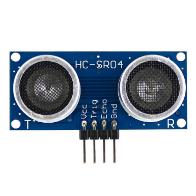
So the ultrasonic Sensor is considered to be a digital sensor because the microcontroller reads a digital signal from it. How the Ultrasonic mainly works, is by emitting an ultrasound at 40000 Hz which travels through the air and if there is an object or obstacle on its path, it will bounce back to the module. Considering the travel time and the speed of the sound you can calculate the distance.
The HC-SR04 Ultrasonic Module has 4 pins, Ground, VCC, Trig and Echo. The GND and VCC pins of the module need to be connected to the GND and the 5V pins on the Arduino Board respectively. Lastly the trig and echo pins to any Digital I/O pin on the Arduino Board.
In order to generate the ultrasound you need to set the Trig on a High State for 10 µs. That will send out an 8 cycle sonic burst which will travel at the speed sound and it will be received in the Echo pin. The Echo pin will output the time in microseconds the sound wave traveled.
Testing IR Distance Sensor
The distance sensor produced by Sharp is a popular and relatively low cost solution for measuring distance. In this test we will use the 2YOA21 model and the characteristics of this sensor are:
Minimum Measuring Distance = 10cm
Maximum Measuring Distance = 80cm
Infrared Proximity Sensor
Analog output inversely proportional to distance
Sensor is Ratiometric
Operating Supply Voltage = 4.5V to 5.5V
Average Supply Current – Typical = 30mA
Response Time = 38 ± 10ms
The IR distance sensor is connected to a voltage supply, and connected to an analog input to the micro-controller. The microcontroller reads an analog signal, which is technically a value of voltage between 0 and 5V. Based on the value recieved you can deduce the distance between the sensor and an obstacle.
Comparing Results
Concerning the Ultrasonic Distance Measuring sensor, you can easily read the information from it on the Serial Monitor, as the signal received from it, is a digital signal, which is converted directly with the help of the existing libraries into the measurements and numbers we need.
However, on the other hand, with the InfraRed Sharp Distance sensor, it is a bit harder to get data from it, because you need to calibrate it first. The IR sensor sends analog data to the Arduino Board, which is technically a variation of the voltage. Thus, what you can read on the serial monitor is a variation in voltage. To convert that into readable information, we should check the values we read with respect to various set distances and calibrate accordingly.
The video represents how the signal is sent and received from and to the arduino board. The signal received at the ECHO signal by the arduino board is a digital signal that represents the variation in distance. On the other hand, the picture represents how the signal is received from the IR sensor. It is mainly a voltage level that variates according to the distance.
You can check the full assignment by clicking on the following link:
For the individual assignment we had to measure the signals of at least one input device by adding it to a microcontroller. That would in turn be added to a PCB.
Since this week is followed by Output week, I decided to mill my PCB to include the output devices I was gonna use. Because I am using these weeks to further experiment on something related to my final project, the outputs in my case are water pumps, and therefore had 2 relays as outputs.
Find the steps taken below:
First a brief list of the tools needed/used:
Roland MDX-40 is the Desktop CNC machine we are using to mill the copper boards.
Tektonix TBS 1052B is the oscilloscope used to observe the operation of the microcontroller circuit board.
National Instruments VirtualBench was used as a digital oscilloscope to observe and document the operation of the microcontroller circuit board.
FLUKE 179 was the multimeter used throughout all the process.
ProsKit SS 207 was the soldering iron used for welding the components.
was used to write the code and upload the code the the PCB.
Before going on manufacturing my PCB, I wanted to test the input devices on the arduino. I tried 2 main inputs
Ultrasonic Sensor: the way this sensor works is by having two components and four pins, trig, echo, VCC and GND, trig sends a soundwave that bounces on the surface infront of it and comes back to the echo pin where it calculates the time it took for the sound to come back and comes up with a set distance. I also watched this on the serial monitor and serial plotter shown below.
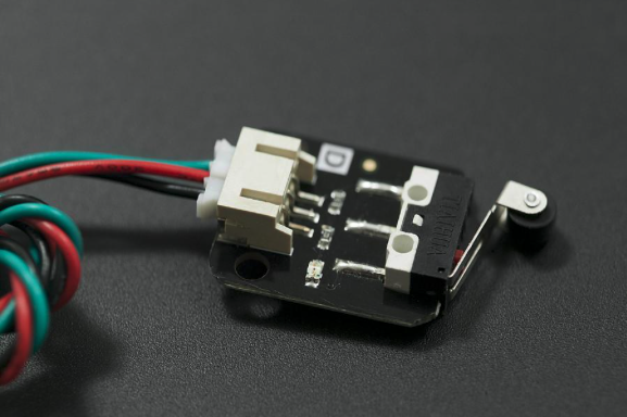
Crash Sensor: the way this sensor works is basically a switch, it has 3 pins, VCC, GND and Signal. This sensor is relative to a button only it has a longer arm with a wheel at the end to ease physical access to switching. I will be using this sensor for my final project which is why I went for it this week.
Now that the input sensors have been identified, it is time to mill the new PCB to handle these two sensors. Since I was looking for effeciency, I had additional pins sketched to be able to add a relay module that would be further explained in the Output as it is part of my final project.
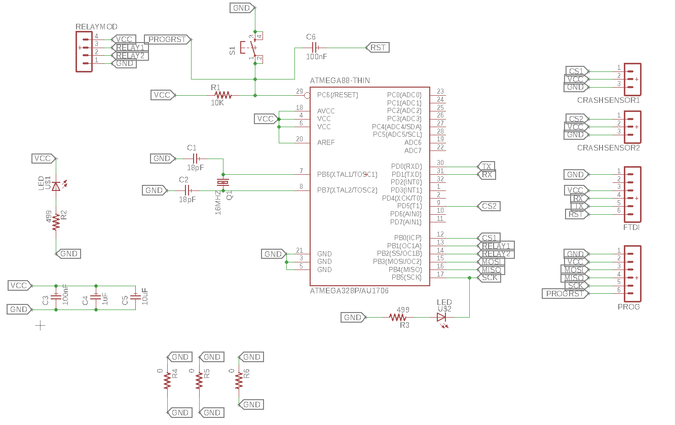
To design the new PCB, I followed the design of the Satchakit which uses an ATMEGA328p and know I need 4 Signal pins for the inputs and outputs and their respective VCC and GND.
Now we need to identify which components should be taken into consideration to have a functional PCB
Reset Button: for the reset of the board similar to the reset on the Arduino.
Reset Pin before the capacitor: used for ISP programming.
Reset Pin after capacitor: used for programing with an FTDI cable.
Capacitors between VCC and GND: Referred to as decoupling capacitors which are used to supress high frequency noise in power supply signals. Basically keeping the voltage constant.
LEDs: For debugging purposes, added between GND and VCC to confirm the board is powered and another between the reset Pin and GND to know when programs are uploaded.
Crystal: used to generate clock pulses required for the synchronization of all the internal operations.
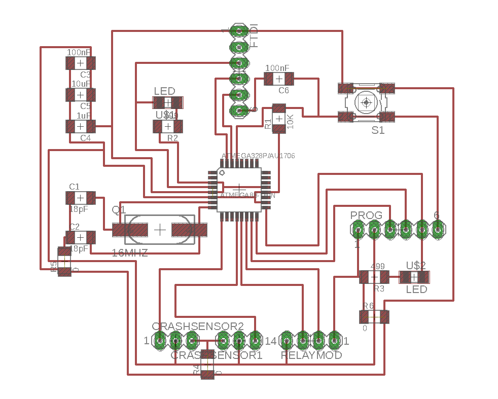
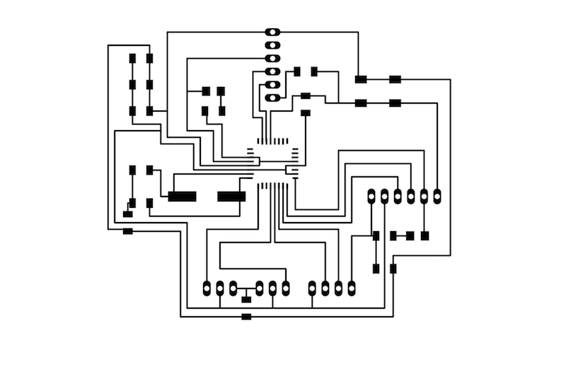
Now coming to the actual design of the PCB, I used the Eagle software which had a final design that is shown below:
Once the design is complete, Export the file in PNG format and open it on GIMP which is used to generate the inner and outer traces to mill the PCB. The inner traces should look like the following:
Once the GIMP photos have been generated, inner and outer traces. Go to Fabmodules to generate the .rml code for the specific milling machine that would be used (Roland MDX-40 in this case). To know exactly how to do so go through the previous weeks to know the exact step by step process. PCB milling steps
Once the PCB is milled it is time to move on to the next step, Soldering.
Have the components ready and set up a safe working space to the this step.
The following components were used in this case:
1 - Atmega328p
1 - 16 MHZ Crystal
2 - 18pF capacitors
2 - 100 nF capacitor
1 - 10uF capacitor
1 - 1uF capacitor
2 - SMD LEDs
2 - 499 Ohm Resistors
1 - 10k Ohm Resistor
1 - Push Button
3 - 0 Ohm Resistor
22 - Pinheaders
I Made the connections in the board to the MCU according to the datasheet of the Atmega328p ( Atmega328p-Datasheet )
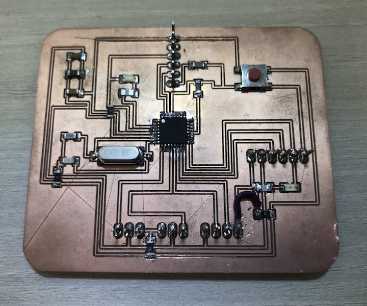
After the soldering process, your PCB should look something like the following: (Note: I added a jumper cable because I experienced some issues with the power distribution and a 0 Ohm resistor connecting the VCCs coming out of the microprocessor pins 4 and 6 trying to resolve the power issue and it did)
Now that the PCB is ready, the next step is to program it.
The following steps should be taken:
Connect the Arduino UNO to the PC.
Select the right port and the Arduino UNO board under tools.
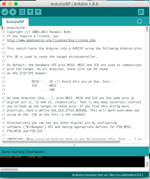
Under >File >Examples, find and open 'ArduinoISP' sketch.
Upload the sketch to Arduino.
Disconnect the Arduino from PC.
Connect your PCB with the Arduino in the following manner:
5V VCC and GND to respective prgramming pins on the PCB
Pin 10 to RST Pin
Pin 11 to MOSI Pin
Pin 12 to MISO Pin
Pin 13 to SCK Pin
Connect Arduino to the PC again.
Select the 'Arduino/Genuino UNO board' and the 'Arduino as ISP' programmer.
Click >Tools >Burn Bootloader.
After the bootloader is successfully done, connect the FTDI cable to program your PCB as if it was an Arduino.
The FTDI connections to this specific PCB pins of the AtMEGA 328p used are as follows:
GND to GND
VCC to 5V
Tx to Rx
Rx to Tx
RST to the reset pin after the capacitor
Now that the PCB is programmable, time to start experimenting with a few inputs.
As stated above, the inputs I will be using are the Ultrasonic Sensor which measures Distance and the other is a Crash sensor which is basically a switch.
The Ultrasonic Sensor has 4 pins, VCC, GND, Trig and echo. Here is a short video to demonstrate it in use and using the Arduino IDE serial plotter to display the data.
The second Sensor I experimented with was the Crash sensor. This sensor has 3 pins, VCC, GND and signal. Again a demostrative video is shown below followed byt the Code.
The Code used for this example:
int inputPin = 8;
int inputPin1 = 5;
void setup() {
Serial.begin(9600);
pinMode(inputPin, INPUT);
pinMode(inputPin1, INPUT);
}
void loop() {
int val = digitalRead(inputPin);
if (val == HIGH) {
Serial.println("Switch 1 pressed");
}
int val1 = digitalRead(inputPin1);
if (val1 == HIGH) {
Serial.println("Switch 2 pressed");
}
}
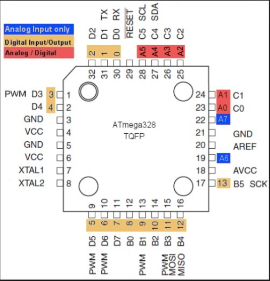
In order to identify which pins are related to your microprocessor, use the image below. This will aid in the coding to know which pin is which. In my case I only used digital pins as they were what I needed. But it is advisable to extend the unused pins for future use just in case.