
You can check the Group Assignment on the following link: Group Assignment
Machines Used
The main machines used in this week's assignment are the CNC Routers. The list of machines we used are the following:- Shopbot 96-60-8 is the main CNC Router available in our lab, having the largest size. It has a working volume of 2.44m x 1.52m x 0.15m.
- Blue Elephant 9060 is another smaller CNC Router we have in the lab. It has a working volume of 0.9m x 0.6m x 0.15m
- Fusion 360 was used for 2D and 3D modelling for the individual assignment (2D for the actual cutting which was then exported in dxf format onto Vcarve and the 3D was to measure the scalability of the design).
- AutoCad This software was used to design the 2D models for the tests that we are going to perform on the ShopBot.
- ShopBot VCarvePro is the main software used by us to produce the g-code for the Shopbot
- Tooling
- Speed and Feeds
- Toolpaths
- Drill Bits are designed to plunge directly into material, cutting axially, and creating cylindrical holes
- Mill Bits are designed to undergo horizontal carving and cutting laterally.
- End Mill Bits
- Diameter
- Shank
- Length of Cut
- Overall Tool Length
- Teath
- Number of Flutes
- Tip Shape represents the shape of the tip for the used tool.
- Coatings
- Center Cutting Capability means the ability to cut both axially and laterally.
- Helix Angle
- Helix Direction
- Ballnose mills produce a rounded pass and are ideal for 3D contour work, because their rounded edge reduces jagged steps when cutting several stepped layers. Ball nose mills can also be used to cut wide paths with rounded edges by reducing the step over amount (overlapping distance between) between passes
- Fish Tail cutters are used to produce a flat surface.
- Surface Planing
- V-carving produce a 'V' shaped pass and are used for engraving.
- Straight These bits are made to skim the surface and leave a smooth flat finish.
- HSS: High Speed Steel A tool steel far superior to carbon steel when used for drill bits and cutting tools. A HSS drill bit can drill a hole much faster than a carbon steel bit, hence its name. Quite the innovation in the 1940's! We moved past this type of tool steel today, HSS bits are only suitable for cutting foams. (some disagreement here)
- SC: Generally just called Solid Carbide. A very tough wear resistant steel. Many forms of Carbide exist (silicon carbide, tungsten carbide, Beryllium carbide, etc.) as do forms with different grain size. Solid carbide router bits can vary from worthless to extreme high quality.
- Carbide Tipped: Carbide is expensive... larger diameter bits are available with chunks of carbide brazed (welded) to a steel body. This reduces the total amount of carbide used to make the bit and hopefully the price. Every thing above applies here. Generally, bits with .1" or more carbide thickness is considered a sharpen-able bit. Note: a sharpened bit may no longer be its full design diameter, and will need to be compensated for in the CNC software.
- OTHER: There are many other exotic router bit materials available... Diamond, Diamond like, poly crystalline, and more. These bit materials tend to be used in specialty, high volume, and niche markets.
- More flutes create a smoother surface finish
- Fewer flutes are best at chip clearing, keep heat from building up
- Two or four flute cutters are the most common.
- The direction, size, speed and amount of chips being ejected can also damage the surface of the work piece. We can control how the tooling effects the material through our end mill type selection (upcut, downcut or compression) and speed at which we cut.
- Spindle Speed
- Feed Rate Feed Rate = Spindle Speed (RPM)* Number of Flutes * Chip Load (inches) = Spindle Speed * Number of flutes * Chip Load = Answer inches/min
- Plunge Rate Use a plunge rate of 50% or less of the feed rate.
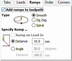
- Ramp is used to reduce the tool breakage and stress on the material being cut. It occurs by ramping the end mill slowly into lateral cuts, where your tool moves in an XZ or YZ 3D incline into your material to reduce stress on your bit when plunging.
- We went with Plywood (15mm)
- And a 1/4 Inch, single flute, upcut milling
- The bit supplier where we got ours from has specified that the chipload should be between 0.004 and 0.006 so we had room to adjust our variable settings as long as we were in the specified scope.
- We decided to go with a chiprate of 0.005 which is in between and adjust the spindle speed and feed rate while maintaining the chiprate based on the equation stated above
- So the Chiprate is a constant 0.005:
CR = RPM x FeedRate
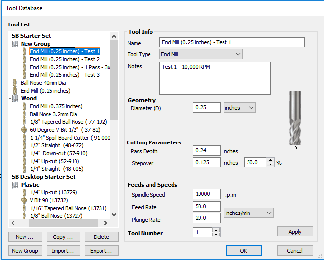
Setting 1: CR = 10,000 x 50, 3 passes (1xD)
Setting 2: CR = 14,000 x 70, 3 passes (1xD)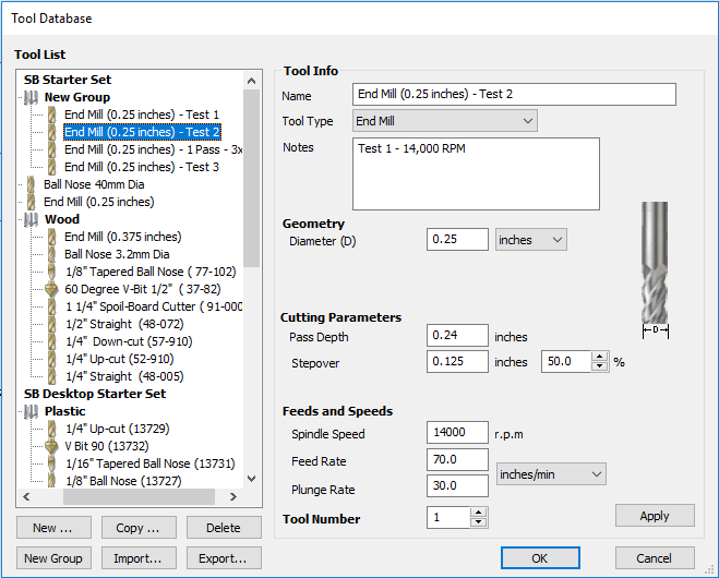
Setting 3: CR = 18,000 x 90, 3 passes (1xD)
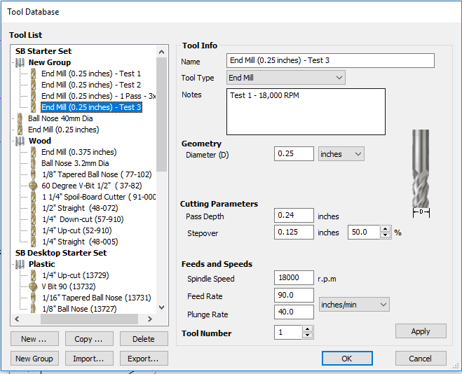
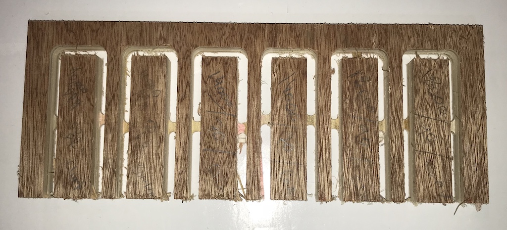
- Above were the Settings we used to perform our tests, each of these was done twice. Once while using the climb setting and the other in conventional setting. The picture below is the test that was made, going as follows from left to right:
Setting 1 Climb, Conventional
Setting 2 Climb, Conventional
Setting 3 Climb, Conventional - This is the raw result, after sanding it would look much smoother.
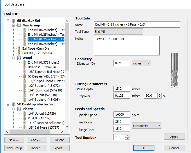
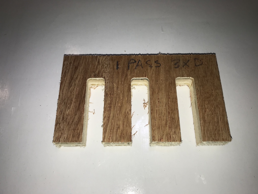
- We also did another test with one pass instead of 3, for this test we had to recalculate the chip rate as it has to be divided on the face of the drill, so the 0.005 chiprate has to be divided into 3 as it is now handling triple the load. The pass was successful and the picture of the settings and final result are found below.
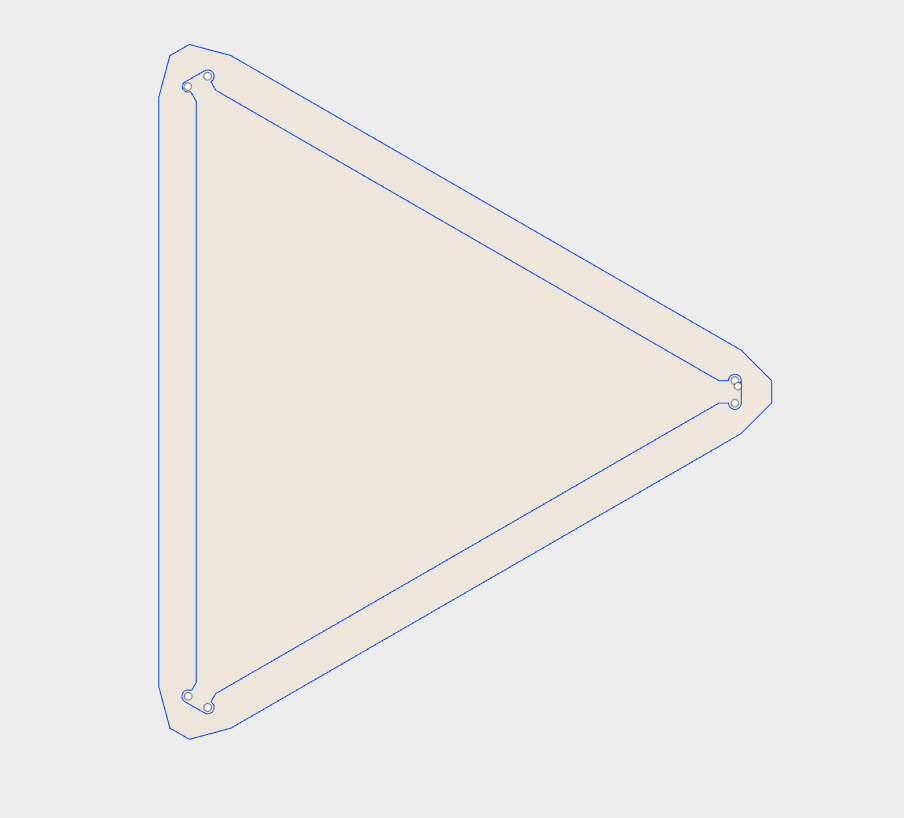
- First I designed my structure using Fusion360
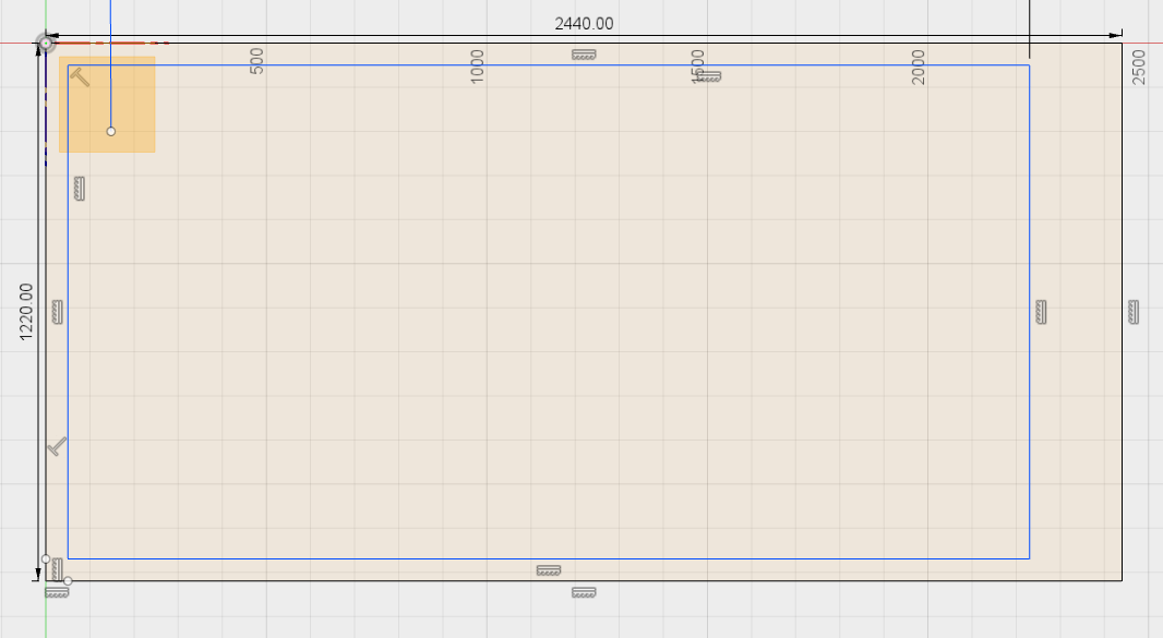
- I first started drawing a rectangle with the dimensions of the actual board I was going to cut since it was basically my only limitation. I then started designing my 2D parts within this rectangle to make sure i would not design something that would exceed my limitation and face drawbacks habing to go back and design again.
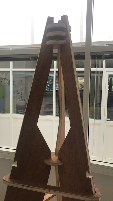
- Since my design revolved around a tripod, I started designing the poles as they were the largest and most crucial parts of my design
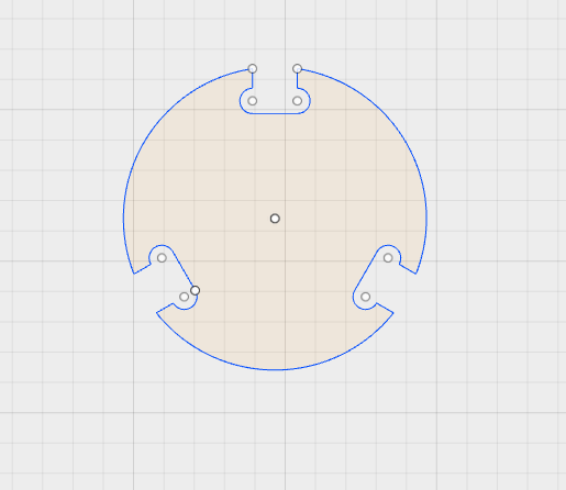
- Then I went ahead and started designing the joints I will have to make to pressfit these poles together. Since it is a tripod, I went with a circular pattern with 3 openings (fittings) 120 degrees apart so they are equally distant.
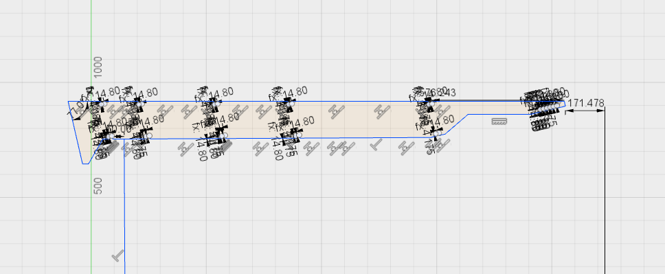
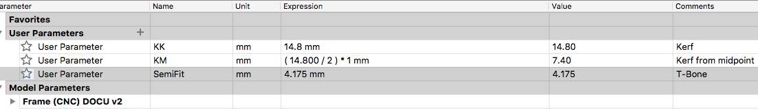
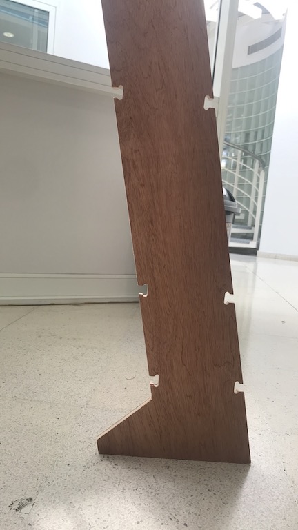
- Then I went ahead and chose where to put the openings for the pressfits on the poles, I added some more along the edges of the poles in case I would need to add some more supports to the structure later on. Since I would be using the same measurements for all steps, I set 3 different parameters, one for the kerf, one for half the kerf (going from the center of a lign), and the semi circles to achieve the T-Bone design.
- And lastly I did some triangles that would fit around my structure and support it externally. I could not do them big enough to support the structure from the bottom, but it did reinforce the top area of the tripod.
- And finally save the file in .DXF format
- Now with the 2D design complete it is time to move on to the CNC.
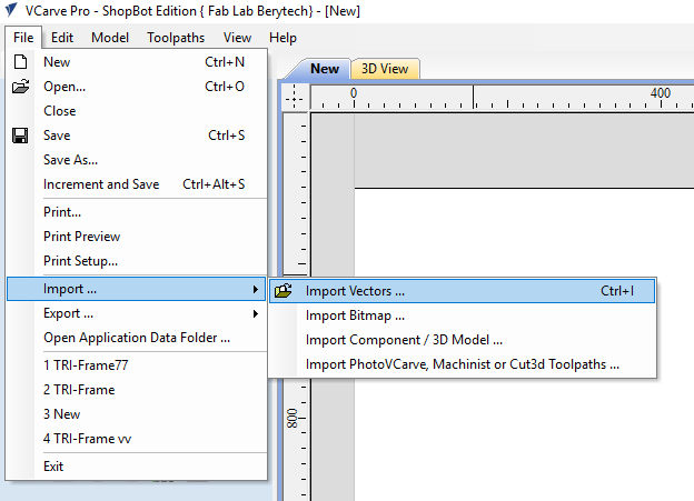
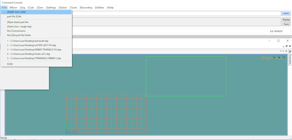
- As stated above the CNC we have at the Berytech Fablab is the ShopBot. In order to generate the Gcode we have to use the V-Carve software.
- The steps to set up V-Carve are as follows:
- First you have to open the file (Import)
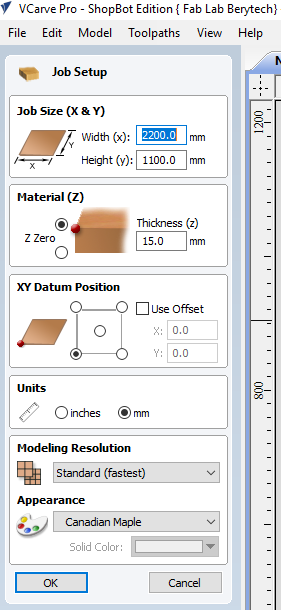
- Input Board Dimensions (As in our case, if you dont have a vaccum bed make sure you take into consideration the edges that are held down)
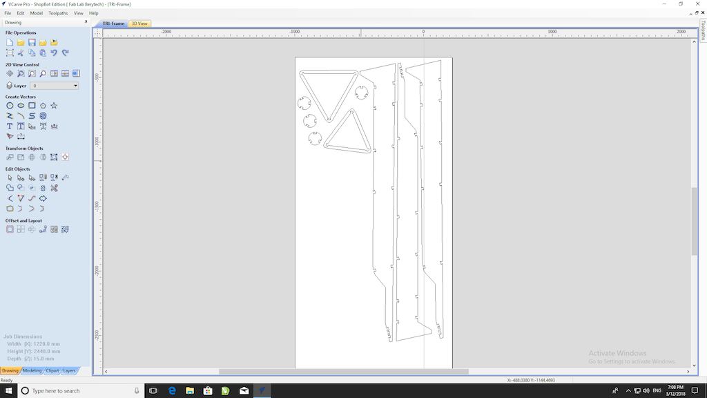
- Now move your design accordingly to the board, the way you set it up is up to you. But try being as efficient as possible
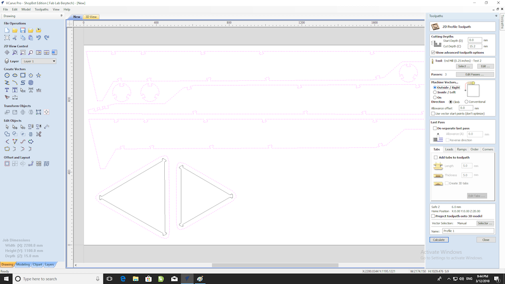
- Your cuts are generally going to fall into two categories, inner and outer cuts. for this step, select your inner cuts (jump to steps after the selecting the exterior cuts down to saving the toolpath)
- Select exterior cuts
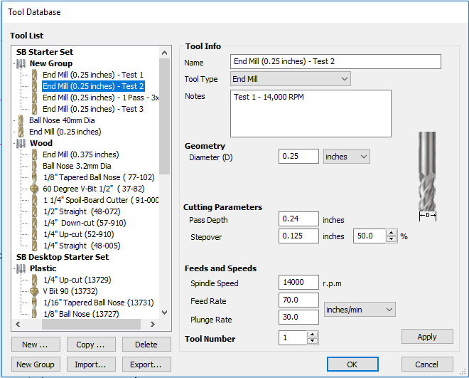
- Select Tool, I chose the tool setting 2 (calculated above)
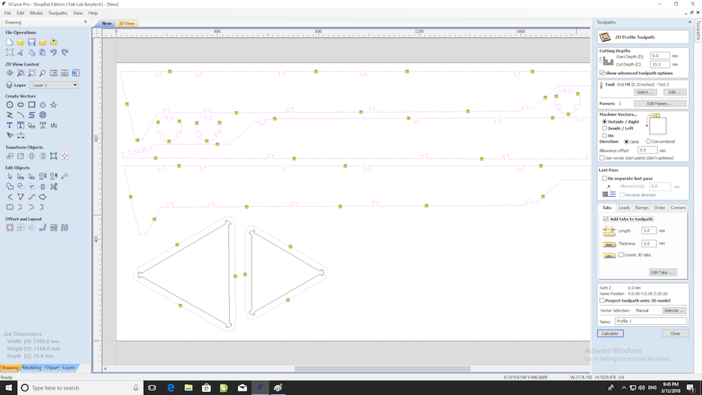
- Insert Tabs, you can either automatically set them (software) or just press on the cut path to add a tab
- Add Ramp
- Save Toolpath
- First Turn on the CNC machine, start with the main switch and then the router switch (Main switch is the Red one)
- Then import the saved toolpath generated in the steps above.
- Open the control panel.
- Move X and Y axis to desired position, at the corner of the board and set them.
- Set Z axis following the steps below
- Set the cable connection on the drill bit holder
- Set the metalic plate centered exactly under the drill bit and press enter on the prompted message on the PC screen
- Before starting the cuts make sure of the following:
- Wear safety goggles
- Hair (long) or clothing are intact and not dangling
- Worktop is clear
- Dust collector is On
- Start the job
- Press start on the remote control panel
- And now wait for the cuts to be done, keep an eye on the process the whole time and keep the emergency stop button close by (remote control panel)
- Once job is over and Router back in set position, vaccum or blow away resting dust and proceed by removing the tabs using a (???)
- Remove cut pieces
- Use sand-paper and smooth out the surface and edges of the cut out pieces
- Join them in the designed (or improvised) way
Softwares Used
The following softwares were used for the Design part in this week's assignment:Some CNC Machining Basics
In order to understand the basics of CNC milling and machining, an intensive research was performed to discover all the variables that affect the CNC machining process.
There are many components that must be taken into consideration when CNC machining, and those mainly are based on the material undergoing machining, the tools used, and the machine itself.
In this section we will discuss the following topics that affect the process of CNC Machining and the final product, and describe how they are connected:
Tooling
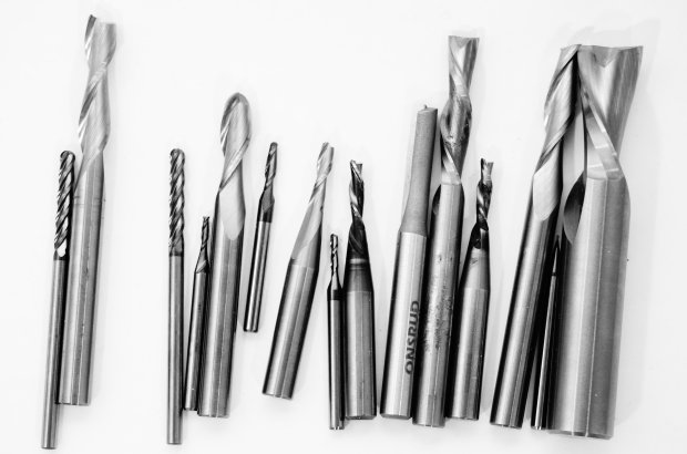
To begin with, there are different tools that are used during the Machining process, each having a specified job.
The main three different tool types available are:
Among those specifications are:
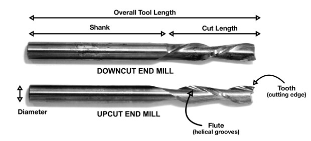
The image below illustrates the different parts of a bit showing the Diameter, Shank, Length of Cut, Overall Tool Length, Teath, and the Flute.
Tip Shape
Concerning the Tip Shape of the End Mill, there are many different tip shapes that are designed for particular purposes. The most common shapes available are the following: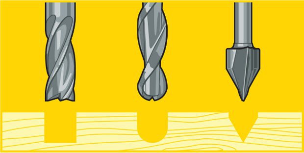
Material and Coating
Concerning the material, you should choose a bit made for the material of your choice. Many manufacturers make bits especial for your material of choice. Bits for hardwood are designed to leave a clean edge. Bits for plywood and laminates are designed so they wonít mangle the outer veneer layers. Bits for plastics are designed to avoid excessive melting. Aluminum cutting bits are designed to clear chips efficiently to avoid rewelding (heated chips getting fused to the hot cutting tool). Many bits can be used for multiple applications so you donít need to buy 30 bits right away if you are in the prototyping stage of your project. A good all purpose bit is a 2-flute up cutting spiral bit.There are many router bit material available and here are some of them:
You can find more details on CNC Router Bit Basics
Helical Direction
A CNC router spins a cutter clockwise. The helical direction of the flutes as they wrap around the tool determine if chips are ejected towards the top or bottom of the workpiece. True to their name, upcut mills eject chips towards the top of the workpiece, producing a cleanly cut bottom surface. The downside is possible surface splintering or ìtearoutî on the top surface as the chips are ejected upwards.Upcutting bits mounted in a CNC pull chips (and your material) up and away from the table. They are great at clearing out chips from your cuts to avoid overheating your bits. They excel at making cuts all the way through material since they just slightly lift the material and scraps up into the end of the bit. Because of the upcutting action, these bits have a tendency to splinter the top surface of sheet goods like plywood and melamine coated particle board. You also need to be very sure that your material is securely held down to the table so the bit doesnít lift it from the table and chuck it across the room.
Downcut tools do the opposite, producing a smooth upper surface. They are ideal for pieces that have been previously engraved or v-carved and cannot be flipped to hide tearout. In addition, as downcut mills pack the chips into the cut path, they can be used instead of tabs to hold down a workpiece and keep it from moving. Downcutting bits press chips and material back into the cut and into the table. The downshearing action of these bits do a fantastic job of preserving your materialís top surface. Since the chips are forced down into the cut, these bits should never be used to drill holes. The friction of the bit against the compressed chips is enough to melt plastics and start wood on fire.
A third option called a compression or up-down bit offers some of the benefits of both up and downcut bits. The bit is a standard downcut bit until you get to the tip. The direction of the cut is switched making the tip an upcutter. This means that you can cut through materials like plywood and you will get a clean edge on both sides. The top is shear down, the bottom is pulled up. Compression bits are never to be used to drill holes. Once the bit has been plunged beyond the direction change, the chips have no way to escape and get compressed creating an extreme amount of friction and heat. Compression bits are a little more expensive because of the complicated manufacturing of the cutting edge but they are my goto bit for nearly all of my wood cutting.
You can find more details on Guide to CNC Bits
Flutes and Chiploads
Number of Flutes Flutes are the helical grooves that wrap around the sides of the end mill. Each flute has a single tooth with a sharp cutting edge (although there can be more than one) that runs along the edge of the flute. As the tooth cuts into the wood, each flute whisks away a small section or ìchipî. The fewer the flutes, the more material that is ejected with each tool rotation. The overall cutting depth should never exceed the length of the flutes on an end mill. If cutting deeper than the length of the flutes, the tops of the flutes will be blocked and chips wonít clear, building up heat and reducing tool life.Chipload Chipload is the thickness of a machined chip as cut by a specific tool type. This is simply the thickness of a chip which is formed during the machining of material. Chipload is important because the proper size chip will carry away heat, promoting long tool life. When the chip is too small, heat is transferred to the cutting tool causing premature bit failure. Too high of a chipload will cause poor edge finish, and transfer cutting load or thrust to the part, possibly causing it to move. A bit in good condition and running at recommended loads will be at room temperature when a cut is finished.
More flutes create a smoother surface finish, while fewer flutes remove material fastest, but make rougher cuts. Proper chipload is important because chips dissipate heat. Hot cutters can lead to suboptimal results, including burned wood, a poor edge finish and dull tooling.
To summarize:
There are many tables that help you choose the chipload of the job you want to do, which will be needed to calculate the speed of the router. The image below represents one of the chip load charts available online.
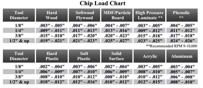
Please note that those represent a specific kind of milling bit. Specific loads for your tools can be obtained from your router bit manufacturer.
Speed and Feeds
The speed at which we move a cutter across the material is called the ìfeed rateî. The rate of rotation is called the ìspeedî and is controlled by how fast the router or spindle turns the cutting tool. Both feed rate and spindle speed will vary based on the material being cut. A general rule of thumb is that you want to move the tool through the material as fast as possible, without sacrificing surface finish. The longer the tool rotates in any one place, the more heat that builds up. Heat is your enemy and can burn your material or radically decrease the life or your cutting tool. Feed rate vs spindle speed: Spindle speed that is too fast paired with a slow feed rate can result in burning or melting. Spindle speed that is too slow paired with a faster feed rate can result in dulling of the cutting edge, deflection of the end mill and possibility of breaking the end mill. A good strategy when selecting a cutter is to attempt to balance feed rate and spindle speed by performing two passes on the work piece. The first pass, called the roughing pass, can be done by using an end mill that will eject a large number of chips at a high feed rate. The second pass, called the finishing pass, then wonít require as aggressive of a cut and can provide a smoother finish at a high speed.Chipload refers to the physical size of the chips the bit creates when making a cut. Higher feeedrates produce larger chips. Higher tool RPM produces smaller chips. If the chips are larger than specified, you risk breaking your bit. If your chips are more like a fine powder, you are probably dulling your bit. It is a balancing act but start with the manufacturers recommended settings and adjust from there.
Chipload = Feedrate / [RPM x number of flutes]
The nominal surface speeds used for various material are shown in the image below.
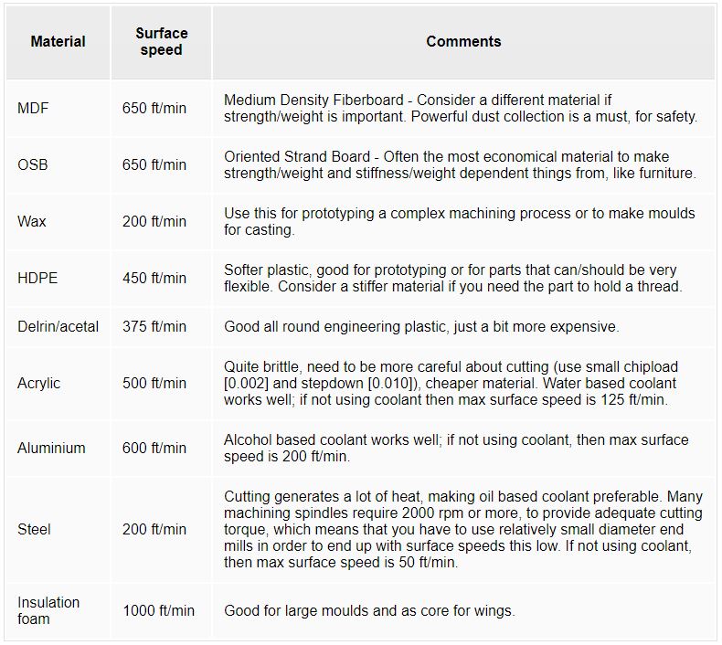
Here are some equations you need to know to calculate the spindle speed and the Feed Rate during any job in mind.

Toolpaths
Many settings can change that control the toolpath of the tool. Among those settings are the following: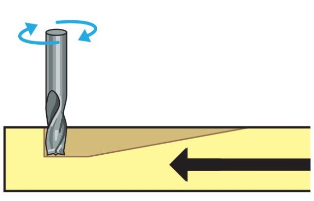
1- Testing the CNC Machine
In this section we will test the alignment of the Shopbot we have in our fab lab, and then test the various outcomes we get when we change the speeds, feeds and toolpaths.
To achieve that, we prepared a file with different settings for the test.
Getting to the actual testing, first we had to identify our material that would be cut and the bit we are going to use.
Conclusion
We noticed that the Setting 2 Climb had the best result in relation to our bit and the material used, so we went on with this setting to achieve our final designs with the individual assignment. It is safe to say that all results were very similar, but the second had the best results as in finishing.
We also calculated the 'KERF' to be able to press fit the pieces together, our result was 14.800mm.
Individual Assignment
Design
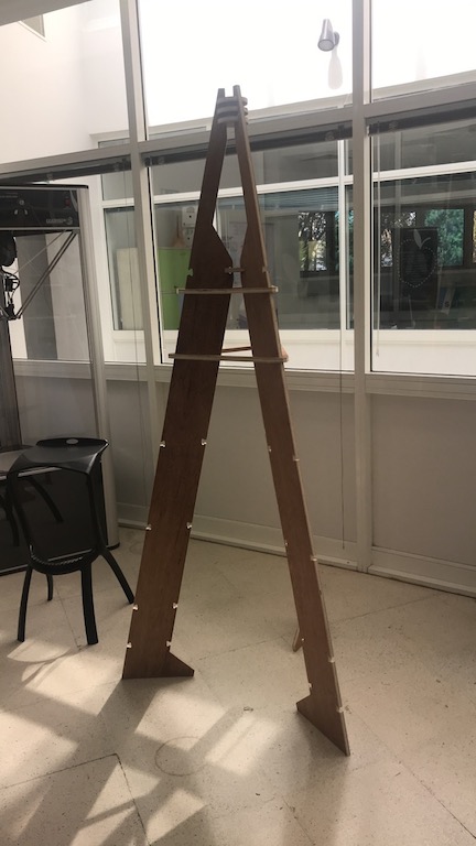
For my design, I decided to do something related to my final project. Which basically needs a tall structure, I cannot say this is the best design for its purpose since the most efficient structure would be standing on 4 pillars. But I wanted to try and design something that would be a bit of a challenge to design in accordance to my level of skills. I decided to do a tripod which would have joints on the top and bottom. Since the tripod would be much easier to handle and falls in well for my final project, only I am not too sure the plywood would be able to handle the tension I am going to need to exert on it. If it fails to be of use for my final project, I have other designs in mind that would include what we are going to learn in the upcoming weeks. That way there is noway what I did would go to waste.
The steps taken to achieve this design are as follows:
G-code Generation

//img src=ADD PICTURE alt="Vcarve">
shopBot (CNC)
Assembly
Final Assembly
Downloads
2D - .DXF fileFusion360 2D file